|
Special Hobby's 1/48 scale
Blackburn Skua Mk.II
by Brett Green
|
 |
|
Blackburn Skua Mk.II |

Special Hobby's 1/48 scale Skua Mk.II is available online
from
Squadron
Background
The Blackburn Skua was an idiosyncratic aircraft. Designed for the
British Fleet Air Arm to perform as both fighter and dive bomber, it
performed neither task particularly well.
Nevertheless, the Skua had the honour of being the first British
aircraft to claim an aerial victory in World War Two. The victim was a
Dornier Do 18 shot down by two Skuas on 26 September, 1939. Skuas were
also responsible for the destruction of the first Axis capital ship of
the war, sinking the German cruiser Konigsberg in 1940.
By June 1940, Skuas on board HMS Ark Royal in the Mediterranean were
the first British fighters to encounter, and to be shot down by, enemy
Vichy French fighters.
The last Skuas were withdrawn from front line service on the HMS Ark
Royal by April 1941. Despite its peculiar assignment and underwhelming
specifications, several Aces scored more than five victories in the Skua.
Special Hobby's 1/48 scale Skua Mk.II in the Box
Special Hobby's 1/48 scale Blackburn Skua Mk.II is typical of recent
releases from this Czech company. The plastic is smooth with a satin
texture. Sprue attachment points are admirably narrow. Surface detail
comprises crisply engraved panel lines combined with impressively
restrained fabric texture on control surfaces plus raised features
wherever appropriate.
In fact, in my opinion, this is the best surface detail I have seen on
any MPM / Special Hobby kit to date.
The kit comprises 97 parts in grey styrene, 6 parts in clear injection
plastic, 38 parts in cream colored resin, 1 photo-etched fret and a
printed acetate film for the instrument panel. Markings for three
aircraft are also provided.
Resin parts are cleanly cast and well detailed. These cover the engine,
wheel wells and the optional Vickers gun. 22 of these resin parts are
individual exhaust stubs.
The canopy is broken down into a separate pilot's sliding section, and
the independent clear part for the rear gunner's clamshell. Clear covers
for the landing lights in the wing leading edges are also supplied. The
transparencies are thin and very clear.
No ordnance is provided, but the centreline bomb sling is present if you
can source your own British 250lb bomb.
In common with most limited run
kits, the first and most important task is preparation of the parts.
The plastic and resin parts were removed from their respective
sprues and casting blocks, and packed into separate re-sealable
bags.
Remember, there are no locating pins on
major parts, so some extra care will be required during assembly to
ensure perfect alignment.
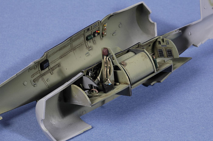
I started construction, not
surprisingly, in the nicely detailed cockpit.
It is very important to note that the
instructions are incorrect in a couple of areas relating to the cockpit:
-
Step 2
shows Part C7 being installed on Part A4. This is incorrect. Part
C7 should be installed at the front of Part C9, the forward cockpit
floor. Part C7 is actually the forward cockpit bulkhead
-
There
is no positive placement for the pilot's seat, Part D4. I recommend
that this part is installed after the rest of the forward cockpit
has been assembled. I initially installed the seat far too low on
the rear bulkhead, which interfered with the fit of the floor.
-
I
built my cockpit as two distinct sub-assemblies - the forward
cockpit ending at the rear bulkhead (Part C5), and the rear cockpit.
This is the best way to ensure a good fit inside the fuselage
halves.
Apart from
these wrinkles, the cockpit was easy to assemble and offered a
well-appointed canvas for painting and extra detail. I added a few wires
and boxes from scrap plastic, plus throttle and mixture handles on the
port sidewall.
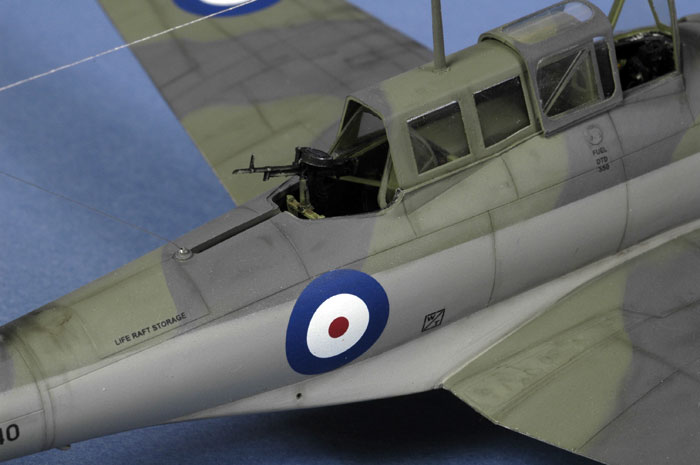
The
Vickers gun mount, Parts B12 and B8, was not yet installed to avoid
damage during the course of assembly.
The
cockpit was painted Xtracrylic XA1010 RAF Interior Grey/Green over a
base coat of Flat Black. I thinned this acrylic paint with Windex and
sprayed it through my Aztek airbrush fitted with the grey-coloured
medium tip. Weathering was by way of a thin oil wash and "chipping"
added with a dark brown artist's pencil. Coloured details were picked
out with a fine brush. Several placard decals from Reheat were applied
inside the cockpit.
Click the thumbnails below to view larger
images:
[../../photogallery/photo00008705/real.htm]
The pipes from the collector ring
to the engine cylinders are provided as 22 individual resin parts.
Combined with the cowl brace and the horn intakes, this assembly
requires some patience and a delicate touch. I glued the pipes to the
top of the engine cylinders, checking alignment with the collector ring
(Part D1) as I went. The cowl halves, Parts D2 and D3, were also
assembled at this stage. However, I did not glue the collector ring to
the assembled engine or the cowl until the cowl, engine and ring were
all painted, weathered and ready for final construction. The horn
intakes (Parts D24) and the cowl brace (Part D6) were also painted
separately and left until final assembly.
A piece of plastic tube was glued to
the rear of the engine in order to ensure a solid fit between the engine
and the front of the fuselage. This was slightly smaller than the
diameter of the hole in the front of the fuselage, so I glued four
pieces of plastic strip to the sides of the tube. These splines ensured
a snug fit inside the fuselage locating hole.
I now turned my attention to the
wings. The casting blocks for the wheel wells are attached to the side
via side strips. This makes clean up and installation much easier than
with a traditional casting block above the wheel well, although some
thinning of the resin wheel well roof and the inside of the upper wing
is still required - especially on the starboard side.
At this point, the fuselage halves
were joined and the centre section of the wing offered to the assembled
fuselage. Fit was really very good, with only a few minor gaps on the
bottom of the fuselage and an almost perfect fit at both wing roots.
There are no locating aids between the outer and inner
wing panels, so I glued a series of small plastic tabs inside the rim of
the inner wing break. Test fitting suggested that there would be a large
step on the starboard side, so I installed a spacer from plastic strip
between the top and bottom starboard inner wing halves.
Click the thumbnails below to view larger
images:
[../../photogallery/photo00014285/real.htm]
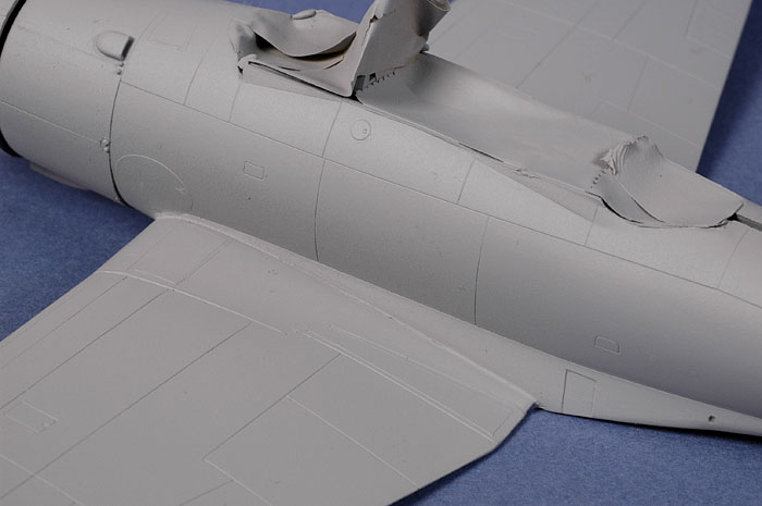
After being lulled into a false sense of security, the
kit's Achilles Heel now revealed itself. Fitting the assembled outer
wing panels to the centre wing section exposed large gaps on both sides
of the upper wing surfaces. I considered a number of solutions including
cutting back the bottom wing fold join, but these proved impractical.
There was no choice other than to fill the gaps, which were around 1.5mm
on one side, and over 2mm on the other.
Fortunately, the plastic tabs were long enough to bridge
the gaps and provide a solid join. Lengths of plastic strip were now
squeezed into the gaps as Stage One of the filling process. Once the
glue had dried, the excess plastic was sliced off with a fresh hobby
blade.
Milliput was then used to smooth the steps and eliminate
any remaining narrow gaps. Heavy sanding followed, which obliterated all
raised and recessed panel detail within 20mm of the wing roots. However,
the result was a smooth surface without too much effort.
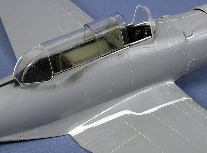
The canopy parts were now test fitted. The sliding
section fitted nicely over the centre canopy, but it was a fraction too
short to reach the canopy sill. I glued strips of .015" x .020" plastic
to the bottom of the sliding section to prevent the dreaded "floating
canopy". I also glued strips to the inside of the cockpit sill to better
represent the canopy rails.
Click the thumbnails below to view larger
images:
[../../photogallery/photo00002529/real.htm]
The missing panel lines were now rescribed - never my
favorite job - by running my scriber along self-adhesive Dymo tape for a
precise result. Raised non-slip walkways were restored using
self-adhesive foil cut to shape.
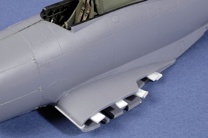
A few smaller details were now dealt with. The horn
intakes for the front of the engine cowling are moulded solid, so I
hollowed out the intakes using a pin vise and a hobby knife. The large
exhaust outlet was also hollowed out using the same method. Four holes
for the wing machine guns were drilled into the leading edges.
Prior to painting, the entire model was sanded first with my Blue Mastercasters
sanding stick, then with 3600 grit Micro Mesh cloth.
The canopy parts were dipped in Future then masked with
Eduard Masks
and sprayed Xtracrylics XA101 RAF Interior Grey/Green prior to the application of camouflage colours.
I primed the entire airframe with Tamiya Grey Primer
straight from the can. I like Tamiya primer, being fast
drying and a good way to quickly check for any persistent gaps or other
surface imperfections before the final colours are applied.
Click the thumbnails below to view larger
images:
[../../photogallery/photo00020445/real.htm]

All remaining painting was applied using the Testor Aztek
metal bodied airbrush fitted with the "Fine"
tan tip.
First, the lower starboard wing was painted white. The
port wing was then painted "scale black" - a 50/50 mix of Tamiya Red
Brown and Flat Black - before both wings were masked.
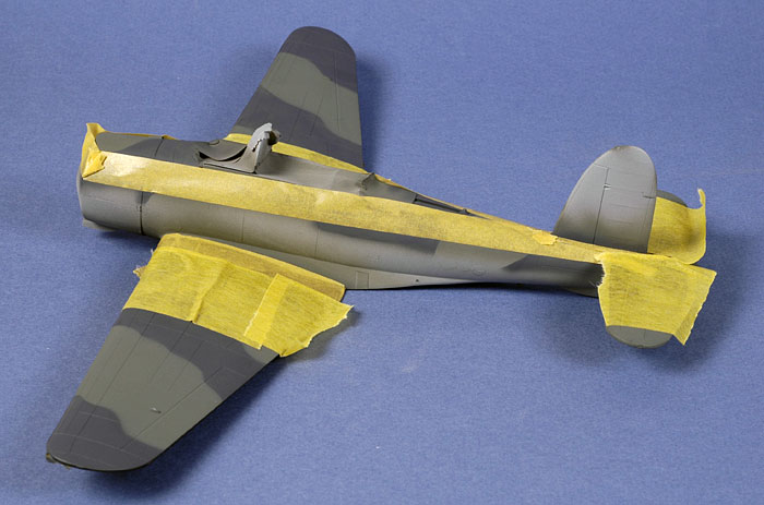
Next, the upper half of the fuselage and the top of the
wings were coated with Tamiya XF-22 RLM Grey. This does not really look
much like RLM 02, but it seems to be a reasonable match for faded Dark
Slate Grey. The disruptive pattern was applied using paper masks lifted
slightly off the surface with small blobs of Blu-Tack to achieve a
fairly hard edged demarcation. After experimenting with a few colours, I
finally settled on Tamiya XF-24 Dark Grey for the "mixed grey" used on
the real aircraft.
The high fuselage camouflage demarcation, wing root and
horizontal stabilizers were now masked with Tamiya tape before the lower
fuselage and fin were painted with Tamiya XF-19 Sky Grey.
Click the thumbnails below to view larger
images:
[../../photogallery/photo00025994/real.htm]
 With
all the major colours applied, it was important to apply a protective
top coat. I find Tamiya paints are almost chalky once applied, and can
very easily be scratched or worn off even with careful handling. I
therefore immediately applied two light coats of Polly Scale Gloss to
seal the paint job. This also created an ideal surface for the decals. With
all the major colours applied, it was important to apply a protective
top coat. I find Tamiya paints are almost chalky once applied, and can
very easily be scratched or worn off even with careful handling. I
therefore immediately applied two light coats of Polly Scale Gloss to
seal the paint job. This also created an ideal surface for the decals.
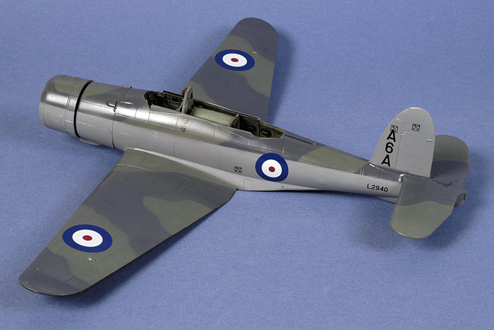
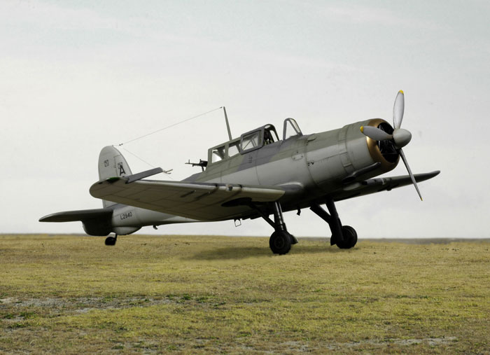
The kit decals were used. Although the box is labeled
"Norwegian Campaign", it would appear that the combination of Type A
roundels on the upper wings and carrier codes on the fin were phased out
by early 1940. I liked the look of these markings, however, and decided
to use the kit decals to depict the aircraft in late 1939 or early 1940,
prior to its Norwegian exploits.
The decals, produced by Aviprint, performed flawlessly
in combination with Micro Set and Micro Sol.
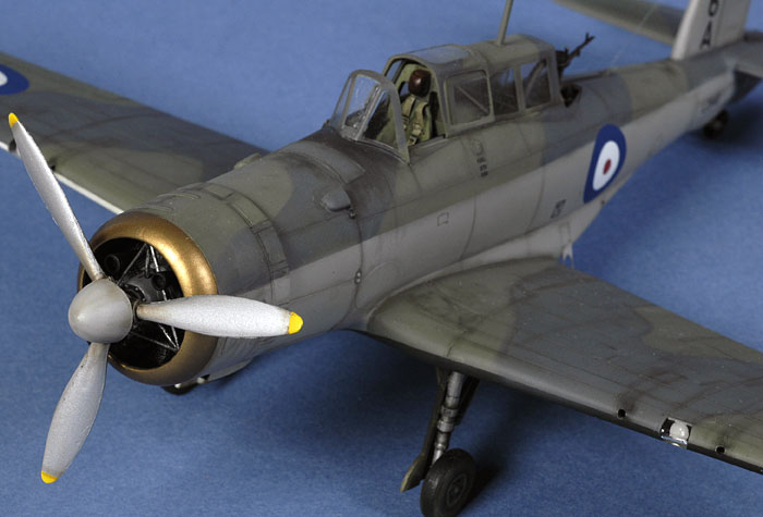
The engine cowl was masked and the cowl ring sprayed
with Testor's Brass non-buffing Metalizer. The exhaust pipe received a
mix of Testor's Burnt Iron and Flat Black.
A coat of Polly Scale Flat Clear was sprayed over the
model before the airframe was shaded with a thin mix of Flat Black
and Red Brown. This was sprayed along control surface hinge lines,
selected panels, in a few random spots and streaks and along the
demarcation line between the Dark Slate Grey and Mixed Grey. This slightly
reduces the harshness of the sharply masked demarcation.
I also made a point of spraying this weathering mix on
the bottom of the wing fillets to emphasise the gull wing effect behind
the bomb recess.
A finishing coat of Polly Scale Flat sealed the
weathering.
Click the thumbnails below to view larger
images:
[../../photogallery/photo00008938/real.htm]
Finishing Touches
The engine components, including the horn intakes and the fine braces,
were installed in the cowl and glued to the fuselage.
The hub and front of the propeller blades were painted silver, while the
back of the blades were painted flat black. The propeller assembly was
sealed with Polly Scale Flat, although I polished the front of the
blades with a fingertip to restore some lustre to this area. The
undercarriage was also installed at this time. I found that the
retraction struts and gear covers were too long, so they were cut to
size before installation.
I had earlier carefully assembled and painted the well detailed and
extremely delicate Vickers machine gun, but I could not find it when I
was ready to install it. To my horror, I found a small, mangled piece of
the gun butt on the floor, obviously run over by the rollers on my
chair! Fortunately, I had a spare Vickers gun from my Classic Airframes
Avro Anson kit.
Click the thumbnails below to view larger
images:
[../../photogallery/photo00023278/real.htm]
The tall canopy lends a large dose of character to the Skua. Without the
canopy fitted, the slim lines of the fuselage and wings are almost
graceful. After the canopy is installed, the Skua looks like a bus.
The clear gunner's clamshell was squeezed into the open position inside
the rear cockpit prior to installation of the other canopy sections.
These clear parts were generally a good fit, but there was a noticeable
gap at the front of the windscreen. This was dealt with using two
treatments of Micro Krystal Kleer. When dry, the windscreen was masked
again and the area sprayed to blend the transparent filler with the
surrounding paintwork.
Wing tip navigation lights were painted using Clear Green and Clear Red
over a base of Sky Grey.
The final job was the aerial wire. Nylon Monofilament (smoke coloured
invisible mending thread) was used for this task, with isolators from
small blobs of Krystal Kleer.
Special Hobby's 1/48 scale Blackburn Skua Mk.II is a well
detailed kit featuring extremely fine surface detail and very nice decal
options.
Being limited run, some extra time and care is required when
preparing and assembling the plastic and resin parts. The nasty gap
between the inner and outer upper wing halves is the only serious
fit issue, but be careful of the couple of errors in the instruction
as mentioned above too.
Keep these couple of points in mind and this kit should not present
any major problems, especially if you have a few limited run models
under your belt already.
Thanks to MPM for the sample
kit.
The model was photographed in HyperScale's studio using a Nikon D70
digital SLR. Illumination was via two studio flash units - one Bowens 250
and a generic 100 flash - on stands and illuminating from a high 45º
angle from each side of the front of the photography table.
The camera was fitted with a Micro
Nikkor 60mm lens.
ISO was set to 250, and the manual
shooting settings were 1/100 of a second at f.29. The high aperture
ensures good depth of field.
The model was photographed against a
plain blue cardboard background.
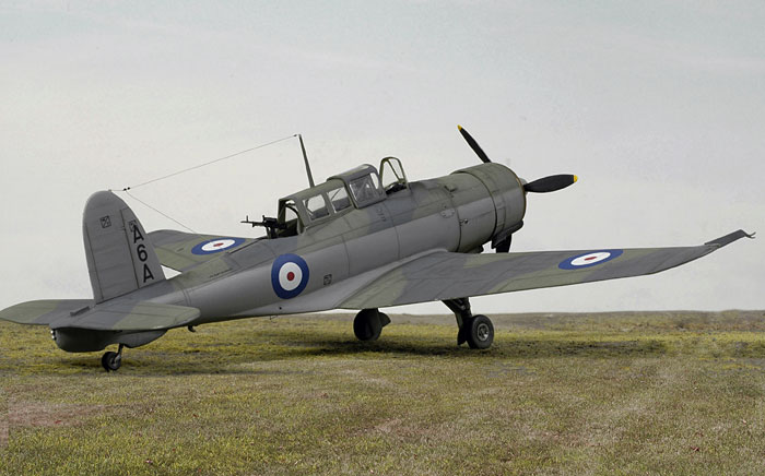
For the scenic images, the model was placed on a base of static
grass in front of an enlarged photograph of sky. The model photo was merged with a photograph
of foreground grass taken
at Bankstown Airport in Sydney's south-western suburbs. The colour and tone of the grass in the airport photo and the
model photo were matched with Photoshop's hue and saturation tool. The demarcation
between the model static grass and the real grass in the foreground was
merged using the Clone Stamp tool.
A number of additional photos were taken
on plain blue cardboard.
All of the images were optimized
(brightness and contrast) in Photoshop CS, resized to 700 pixels in
width and saved as 75 dpi .jpg files using Photoshop's "Save for the
Web" option.
Model,
Images & Text Copyright © 2007 by
Brett Green
Page Created 12 July, 2007
Last Updated
24 December, 2007
Back to
HyperScale Main Page |
 Home
| What's New |
Features |
Gallery |
Reviews |
Reference |
Forum |
Home
| What's New |
Features |
Gallery |
Reviews |
Reference |
Forum |