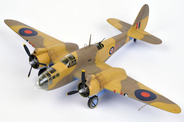
Classic Airframes' 1/48 scale
Martin Baltimore Mk.I
by
Brett Green
|
Martin Baltimore Mk.I
|
Part One - Construction

Classic Airframes' 1/48 scale Baltimore is available online from Squadron.com
Background
The Martin 187 Baltimore was a developed from the Martin 167 Maryland. It was designed to British specifications for a tactical attack bomber that was more powerful and had a larger fuselage than the Maryland.
The original request was for 400 aircraft, to be split between the French and British. Upon the fall of France, the British purchased all 400 and all but a couple were sent to the Middle East.
An additional 1,175 Baltimores were provided to the RAF under Lend-Lease. Late in the war, surplus RAF aircraft were handed over to Free French, Italian Co-Belligerent, Greek and Turkish air force units.
Classic Airframes' 1/48 scale Baltimore in the Box
Classic Airframes released two 1/48 scale Martin Baltimore kits simultaneously in April 2008. One boxing contained markings for British service, while the other kit offered decals for Italian, Turkish, Greek and Free French aircraft.
Both versions shared the same 70 grey plastic, 50 resin and ten clear injection moulded parts.
Typical of recent Classic Airframes kits, detail in important areas such as the cockpit and engines is quite thorough, and surface detail is crisply recessed. Parts are included to depict either a Baltimore Mk.I with the open dorsal gunner's position, or one of the later marks fitted with the Martin turret. Other options include the large tropical intakes for the top of the engine nacelles, "clothes rail" antenna and covered wheel hubs.
Moulding quality is very good, but there is some fine flash around many of the parts. Being a limited-run kit, the main parts do not have locating tabs or pins, so extra care must be taken when aligning parts. Test fitting is also essential.
As with most limited run kits, preparing the plastic and resin parts is the first job. It is also perhaps the single most important task in construction, as careful preparation will make for a speedier and less stressful build.
I spent about 90 minutes removing the plastic parts from their sprues, cleaning up the remaining sprue attachments and lightly sanding the mating surfaces of the main parts. The quality of the plastic is very good - slightly soft so it is easy to work with, a satin texture and very finely recessed panel lines. Care will be required not to eliminate this detail in later sanding.
The resin parts were even faster to clean up.
The most complex resin assembly is the engines. I decided to tackle these as soon as I had removed the cylinders from their casting blocks. The cylinders had a little flash on them, so I used a stiff toothbrush to remove these whisper-like wafers of waste. Don't use the toothbrush for your teeth after this job!
The cylinders plugged precisely into the engine core, with only minimal trimming required where a few cylinders fouled with plumbing cast in place. Test fitting will quickly identify where the trimming needs to take place.
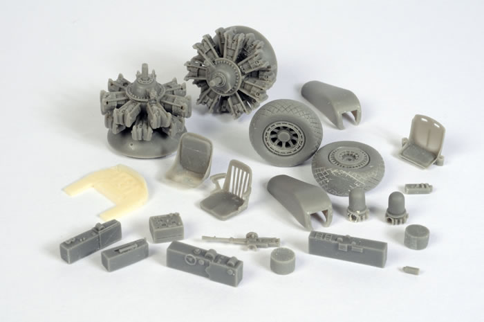
The remaining resin parts were quickly relieved of their casting blocks with a razor saw and, after some additional cleanup with a sanding stick, were also ready to use. Extreme caution is necessary when cleaning out the back of the radio operator's "garden chair". I managed to cut through the bottom of the bomb aimer's seat with the razor saw (I do that far too often), but I repaired the hole with super glue.
The main cockpit components on this kit are plastic. I decided to glue together the main interior structural components but left off the delicate details (such as seats, control columns and instrument panel) until I was sure that the whole sub-assemblies would fit cleanly between the fuselage halves.
In fact, test fitting these partially completed assemblies proved that they were too wide, as the fuselage halves would not fit together when they were tacked in place.
The bulkheads and floors were trimmed and sanded until they were narrow enough to fit without fouling.
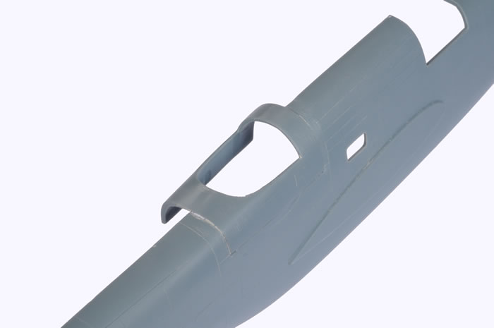
The kit allows the early Mk.I to be built with the open dorsal gun position, but this option does require some surgery. I have always liked this version though, so I set about cutting a section from each fuselage side. This is assisted by recessed panel lines, but care is still required.
I started by deepening the appropriate panel lines with my Tamiya scriber. The vertical lines were then cut through with a razor saw. The remaining horizontal cut was made with a new hobby blade.
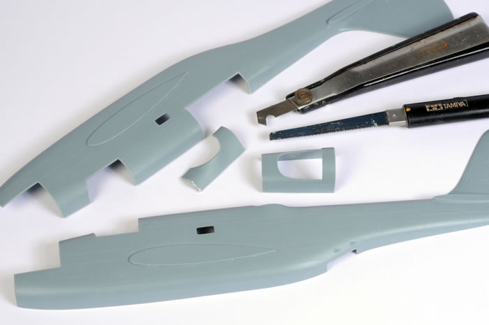
The new open gun position was glued onto the starboard fuselage half. The fit was actually very good.
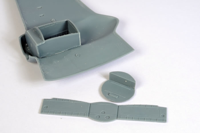
Most of Classic Airframes' models feature resin wheel wells. These are always well detailed, but they can sometimes lead to complications with fit - the resin needing to be thinned considerably to permit wing halves to join cleanly. In this case, Classic Airframes has supplied a neat folding plastic wheel well.
Although the idea looks peculiar at first, it actually works pretty well. The back wheel well wall and both sidewalls are formed from a single length of straight plastic with two bevelled grooves. The plastic is bent along the grooves and glued to the circular front of the engine firewall before the entire assembly is attached to the inside surface of the upper wing.
I ran some liquid glue along the insides of the wheel well walls to reinforce the folds/joins.
Fit was perfect.
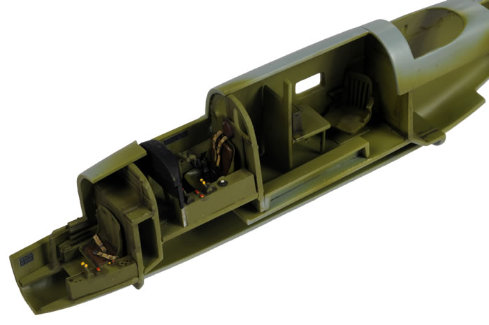
With the interior floors and bulkheads trimmed and thinned, all the cockpit components were painted US Interior Green using Gunze paints. It is a great shame that the beautifully detailed radio operator's chair is completely hidden inside the dark recesses of the fuselage, as it is a wonderful example of the resin caster's art.
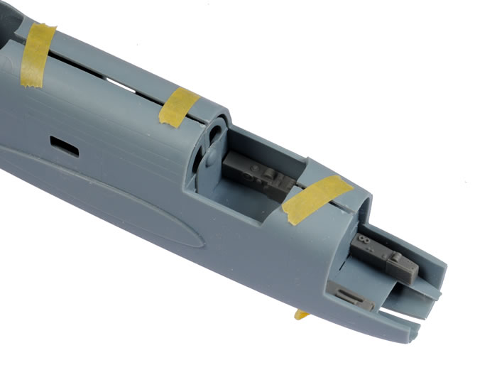
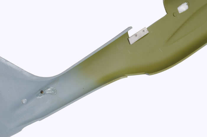
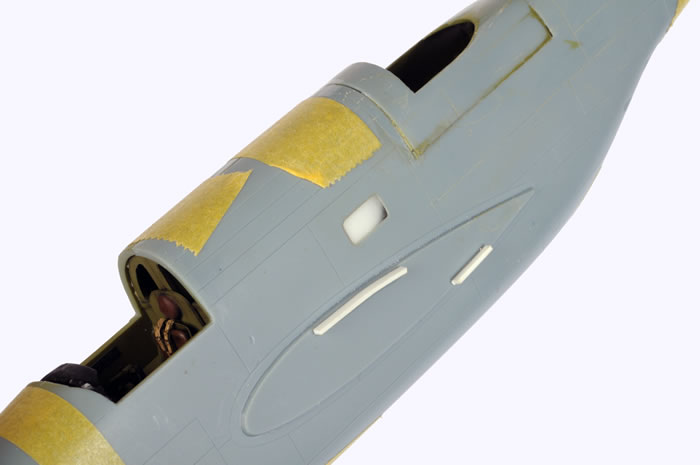
I glued a rectangle of plastic to the mating surface of the dorsal gun insert to reinforce the join after the fuselage halves were joined.
You can also see that the small fuselage window is cloudy in the photo below. I applied a blob of Micro Krystal Kleer to the window as a mask in preparation for painting.
Also note the brass wire below the tail. This was used to reinforce the join with the horizontal stabilisers.
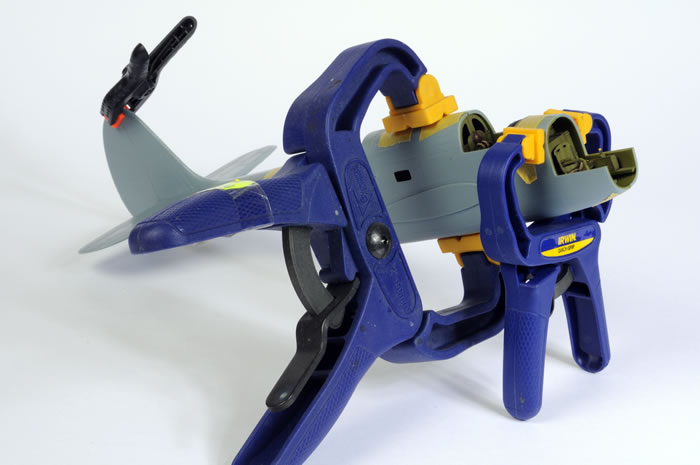
Irwin clamps act as an extra pair of hands while the glue sets.
This helps ensure the best possible alignment, and a gap-free finish between major components.
The big wings are simply butted against the fuselage - no locating tabs here. I reinforced this join with a couple of strips of styrene at the wing root - one at the top join and one near the bottom trailing edge.
The horizontal stabilisers display a noticeable backward sweep. See the strange angle of the elevator hinge lines below. When I noticed this, I checked references which seemed to confirm that the elevator hinge line should be at 90 degress to the fuselage centreline.
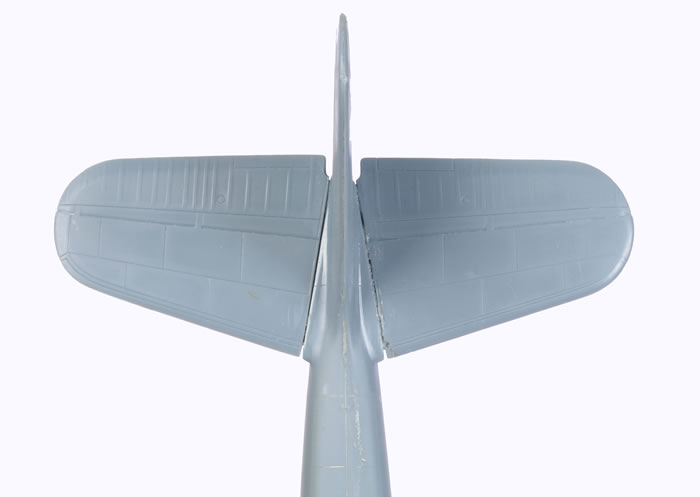
I therefore broke off the horizontal stabilisers and cut a wedge out of the mating surfaces. When the parts were glued back on, they looked much more sensible.
Now it was time to join the wings. The fit was really very good in this area with just a hint of filler required at the leading and trailing edges.
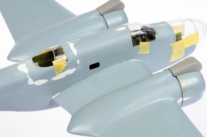
I also test fitted the clear parts. A good fit would be imperative on this glasshouse nose. Fit looked like it would be okay in this area too.
A few key areas required filling. The joins on both sides of the dorsal gunner's position were the most obvious. but some seams and join lines on the fuselage centreline and the engine nacelles also required attention.
I used Milliput White as my filling weapon of choice. I like Milliput because it is slow setting, so it remains workable on the model for 15 minutes or more, and it is structural, so it will fill large gaps.
To be continued.
Model, Images and
Text Copyright © 2008 by Brett Green
Page Created 17 December, 2008
Last Updated
19 December, 2008
Back to HyperScale
Main Page |
 Home
| What's New |
Features |
Gallery |
Reviews |
Reference |
Forum |
Search
Home
| What's New |
Features |
Gallery |
Reviews |
Reference |
Forum |
Search