Dragon 1/32 scale Bf 110 C-7
Instructions Errata List
by
Brett Green

Dragon's 1/32 scale Messerschmitt Bf 110 C-7 will be available online from Squadron.com
I have finished basic construction of Dragon’s 1/32 scale Messerschmitt Bf 110 C-7.
The good news is that detail and fit are generally excellent. Assembly is somewhat more complicated than I expected, especially around the cockpit and engine nacelles. For more detail on the kit contents, you may view the FirstLook review posted elsewhere on HyperScale.
However, by far the biggest hurdle has been the instructions, which contain a number of errors and omissions in some very important areas.
I have listed the errors and omissions that I have found to date. If you are planning to build Dragon’s excellent 1/32 scale Bf 110 C, you might like to print this list to supplement the instructions.
Instruction Errata List - 16 September, 2008
Step 1:
-
The pilot’s throttle quadrant is incorrectly labelled part E46 on the instructions. It is actually part D46 on the sprues.
-
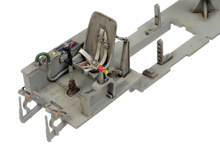
Part D20 is a rack for an extra MG/FF ammunition drum. It should not be installed on part E19 as illustrated. Also there is a second part D20 not mentioned in the instructions. These two "L" shaped racks should be installed on the mid cockpit floor (part E14) on either side of the opening for the MG/FF mounting tray (see photo below for their location and orientation).
Step 2:
-
Part E3 is a long fairing that should be installed at the top of part E13, the starboard sidewall. This is not mentioned in the instructions.
-
Part E1 is a small box that should be installed on the port sidewall. The part is pictured as installed, but not mentioned in the instructions.
Step 3:
- Part D59 is the trim wheel. This should be installed on the upper port side of the pilot’s cockpit. This part is not mentioned in the instructions.
Step 5:
-
The engine rocker covers (parts J23 and J24) should only be installed after the rear engine parts, as these fit over locating tabs moulded onto part J27.
-
Parts H16 are engine instruments. These are not mentioned in the instructions. Part H16 should be installed on the inboard engine mount for each engine (parts J17 and J18). These will need to line up with the three small holes in the side of the engine covers.
Step 6:
-
The illustration of the exhaust panel seems to show the parts back the front. Check carefully before assembly.
-
I would recommend leaving the installation of the exhausts until the rest of the model has been assembled. There does not appear to be any way to secure the exhausts to the exhaust fairings.
-
The rear wheel well arch supports (parts A5 and A6) should not be attached to the wheel well ceilings (part N12 and N13) as illustrated. There is no locating position on the wheel well ceilings for these arches. However, there is a positive locating groove inside the rear of the nacelles. The arches should be glued into these grooves.
-
Double-check the front firewall for the wheel wells (parts F34 and F35). These may be incorrectly labelled on the instructions. If the wrong combination is fitted, the wheel well and engine assembly will not fit inside the engine nacelle properly. I had the wrong bulkheads installed and did not find out until attempting to install the wheel wells. I had to remove and swap the bulkheads (this might have been my mistake, but check carefully and test fit anyway)
-
Parts F15 and F16, the main gear door actuators, should be glued to the gear legs (parts F17 and F18) in Step 6, not in Step 8.
Step 8:
-
The radiator faces (parts C2, C3, C4 and C5) are pictured with the faces pointing inboard (i.e. toward each other). The grille detail should actually be facing outward. They also appear to be pictured upside down. These parts should actually be fitted into recesses in the bottom of the wings. The locating slots make their positioning quite clear.
-
Parts N5 are small braces for the radiator. These are not mentioned in the instructions. The braces should be installed near the front opening of the radiators.
Step 11:
- Part N29 is the pitot tube for the later Bf 110 E. Do not open the locating hole or install this part. The correct part for the Bf 110 C and D is the “T” shaped pitot tube, part N8. This part is pictured installed in Step 11, but it is not mentioned in the instructions. The locating hole for this part is already open in the bottom of the starboard wing.
Model, Images and
Text Copyright © 2008 by Brett Green
Page Created 16 September, 2008
Last Updated
16 September, 2008
Back to HyperScale
Main Page |
 Home
| What's New |
Features |
Gallery |
Reviews |
Reference |
Forum |
Search
Home
| What's New |
Features |
Gallery |
Reviews |
Reference |
Forum |
Search