|
Scratch Built 1/48 scale
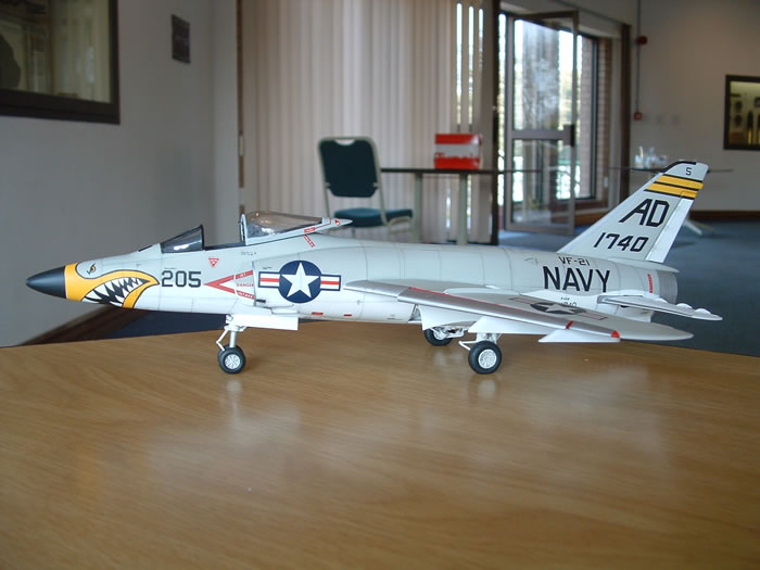
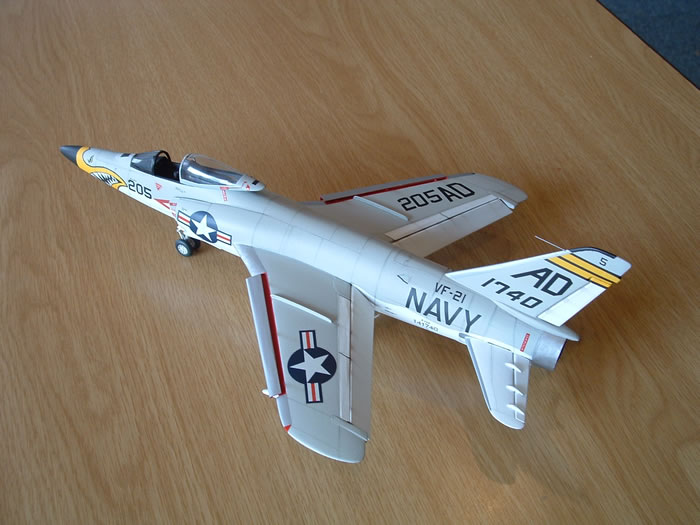
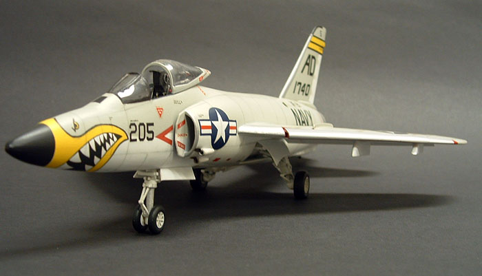
Grumman F11F Tiger
by
Frank Martinez
|
Grumman F11F Tiger |

HyperScale is proudly supported by Squadron.com
My name is Frank Martinez, I am 46 years old and a keen scale modeler living in Johannesburg, South Africa. I am a member of the Johannesburg IPMS Gold Reef Scale Modellers Society
This project began when I saw an article in the Fine Scale Modeler’s Great Scale Modeling 2004 magazine showing some of the jet aircraft models by John Eian.
In this article there was a photograph of an F11-F Tiger built from the old Lindbergh 1:48th scale kit. In it the author said that he had heavily modified, corrected and detailed this kit in order to bring it up to an acceptable standard. In the article the author states that this project had taken him 20 years.
For four years I kept this article and was always on the look out for this kit. To my knowledge, the only other 1:48th scale kit of this aircraft is the Fonderie Miniatures kit consisting of injection molded plastic, resin, and some white metal parts. Unfortunately, this kit is very expensive and could not afford the exchange rate, shipping and import charges to get it to South Africa.
Over the years I was on the look out for any information on this aircraft and eventually came across an old copy of the “In detail and scale” book on the F11-F Tiger by Bert Kinzey. To my surprise included in the book were a set of drawings showing a side view, top view and cross sectional profiles all along the fuselage and wings.
Planning
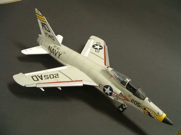
In order to build the model I had envisioned a construction method of creating an internal framework of stringers and ribs (very similar to those constructed by radio controlled aircraft). I would then either “skin” the outside of the framework with strips (like the ship builders do) or fill it internally. The external surfaces of the fuselage would then be sanded smooth to achieve the “area rule” shape of the fuselage.
I believed that the simpler method would be to fill and then sand, but it was a case of finding the correct material for that process.
A casual conversation with a fellow modeler revealed that he had used a polyester resin automotive body filler for a similar purpose when constructing ship hulls, and that it was very easy and quick to construct complex hull shapes with multiple compound curves.
With this information, I got some of this product called Soudal Plastic Steel and set about purchasing 1,5mm and 2mm thick Evergreen styrene sheets for making the frame structure.
Constructing the frame structure
As I do not have access to a digital camera, I have not been able to provide a stage by stage picture of the construction process, so what follows is a verbal description of the construction process.
I first scaled up the 1:72nd scale drawings in the book to 1:48th scale in a photocopy machine by increasing the images 150%.
I then cut these paper copies out carefully using an X-Acto knife. The profiles I used were the side view, the top view, and the fuselage cross sections
The side view and top view profiles were then glued to the 2mm thick plastic card sheet using Pritt paper glue. Once dry, I then used the Tamiya scribing tool to cut out the profiles by running the scribing tool very carefully along the paper edge. Although the plastic may appear very thick, the scribing tool will cut through very quickly.
The fuselage cross sections were then glued to the 1,5mm thick styrene sheets also using Pritt paper glue. As these profiles are mostly circular or oval in shape, I used a pair of scissors to cut them out of the plastic sheet and then used emery boards of different grades to shape and smooth the profiles.
The paper patterns were then pealed off all profiles leaving the bare plastic shapes which were then marked in pencil to identify each one for construction. The location of each fuselage cross section was then marked on the top view and side view profiles for reference.
The top view profile was then cut in half and glued to the side profile in order to create a cruciform shape when viewed from the front. The fuselage section profiles were then cut into quarters and glued in the four quadrants at each location. In this way a three dimensional frame was created defining the outer edge of the fuselage at various points along the length of the fuselage.
It should be noted that when cutting any of the profiles, an allowance for the thickness of the surface being glued on to must be made. If this is not done, the overall width of the fuselage will be too wide, or the profile will stand proud of the side view or top view profiles.
I used Tamiya liquid cement to position all profiles checking for squareness and straightness, and once correct, thin cyanoacrylate glue was run along all edges for strength.
The position of the cavities for the cockpit, wheel well and main landing gear were now determined, marked, cutout and boxed in with 1mm thick sheet styrene from the scrap box. The tail cone/exhaust outlet was created using a tube made from a rolled strip of sheet styrene 1mm thick.
Filling the frame structure with filler
In order to minimize the amount of filler to be used, and to reduce the total weight of the model, flat rectangles of sheet styrene 1,5mm thick were glued at an angle in between the fuselage section profiles thereby creating triangular cavities which would not need to be filled. An additional advantage of this is that they added additional strength to the frame structure.
The Soudal Plastic Steel automotive body filler is two part polyester which when mixed will give you approximately fifteen minutes to apply and work worth. I n approximately thirty minutes, the filler is cured, hard enough to begin sanding.
Every cavity was now filled and once cured sanded to shape. It should be noted that a small amount of shrinkage with the filler does occur, and that you should over fill the cavities with filler and then sand. In those places where shrinkage does occur you simply reapply and then sand smooth.
The edges of the styrene shapes which created the fuselage frame now will become the guides to how far you need to sand. I did notice that in some places, especially very thin filler sections, very small separation cracks began to occur between the filler and the styrene profiles. In order to correct this I simply ran very thin cyanoacrylate glue which acted as a bond and filler. In retrospect, to correct this in future I will roughen the styrene surface, thereby improving the fillers adhesion.
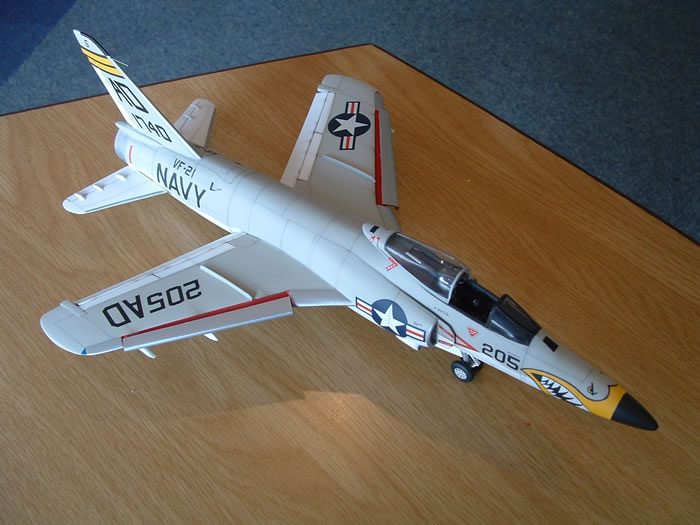
Wings and control surfaces
The main wings, tail planes and vertical tail were constructed from a sheet of styrene cut to the correct shape and then laminated on both sides with very thin polyurethane foam sheet. The shape of these surfaces was then sanded to the correct profile and then given a coat of Soudal Plastic Steel automotive body filler. As the polyurethane foam is porous, adhesion of this very thin coat of filler is very good. The surfaces were then sanded smooth to finish off the profiles. The control surfaces were then marked off and cut out using a sharp X-Acto knife. The control surfaces included all ailerons, moving surfaces and leading edge slats.
The control surfaces were then constructed from sheet styrene (for a sharper finish) and the resultant cutouts in the wings and tail plane and tail were lined with sheet styrene and sanded smooth. Wing fences and additional details were added to the top of the wing surfaces made from sheet styrene.
The wings, tail planes and vertical tail were attached to the fuselage by drilling holes through the fuselage and corresponding holes in each wing etc. Brass pins of various diameters were used to locate, mount and secure these in place.
The resultant gaps between the wings etc. and the fuselage were filled using Tamiya grey filler and sanded smooth to achieve a blended effect.
Cockpit, undercarriage, and exhaust details
The cockpit details were constructed by cannibalizing spare instrument and side consoles from a friend’s spare box (F4 Phantom parts to be exact!) The seat, control column, foot pedals and instrument panel coaming were scratch built using different thicknesses of sheet styrene.
The windscreen and canopy were cannibalized from a Matchbox 1:48th scale FJ4 Fury kit sanded and modified to suit resulting in a very similar appearance to that of the original. The canopy actuation details were constructed from styrene sheet and rod and super glued in place.
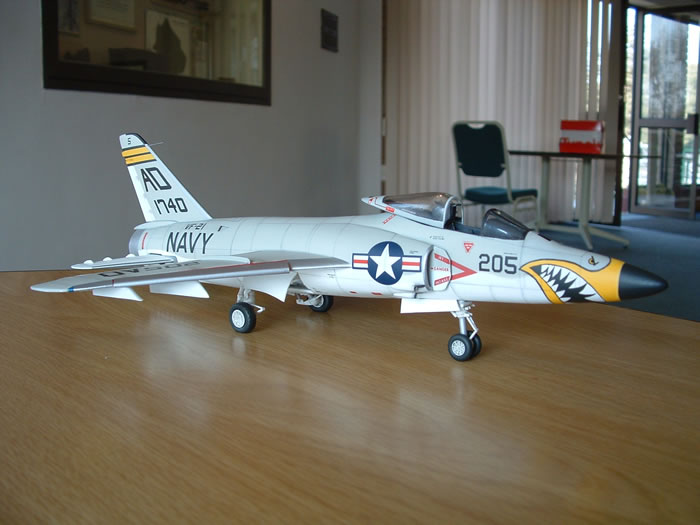
Owing to the substantial weight (in comparison to an injection molded kit) the undercarriage was constructed from 2mm diameter aluminum rod for strength.
Styrene tube was pushed over the aluminum to create the effect of hydraulic cylinders/oleo struts and small strips and rods were super glued to these to create the effect of the many details associated with these mechanical members. A feature of the F11 Tigers undercarriage is that each wheel is actuated by no less than four hydraulic cylinders. For the really small one s my friend’s spares box again came to the rescue.
The wheels were also sourced from his spares box being lucky enough two main undercarriage wheels of the right size (bulged and flattened to simulate weight) and approximate hub pattern and two forward undercarriage wheels.
The undercarriage doors were made from laminated sheet styrene to get the right pattern of cutouts and lightening recesses which each door features.
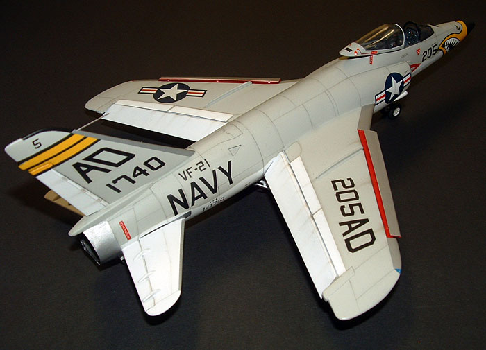
The exhaust is made from a thin aluminum sheet profiled and glued into position. This part of the model was probably the most difficult as it had to conform to the fuselage shape in this region and still retain its distinctive flat bottomed shape. To achieve this, a number of paper and masking tape patterns were traced, cutout and test fitted to get the correct shape. The aluminum sheet was then cutout, and fitted to the fuselage.
The aircraft excluding all details was given several coats of Duco automotive grey primer. This primer is very good for filling any minor surface defects and hardens to a very sandable finish when dry. The model probably has six coats in total every time sanding in between coats to minimize any surface defects.
Once surface preparation was complete a final coat of Tamiya grey primer was applied. I have found this primer to be very good as a base for the application of acrylic paints.
The underside of the model was sprayed using Tamiya white primer and then sealed with Tamiya TS13 Clear. The top surfaces were airbrushed with Lifecolor Light Gull Grey acrylic paint. Once dry the complete model was given a coat of Tamiya TS13 Clear.
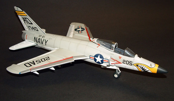
The main challenge in the decaling came in the distinctive shark mouth applied to the F11 Tigers of VF21. Not mentioned in the introduction, is that I had bought a 1:72nd scale Hasegawa kit of the F11-F Tiger and used this for reference all through the build. To help with the decals I had a color transparency made of the decal sheet enlarged 150% to 1:48th scale. I then used this as a guide for creating patterns of the shark mouth using Tamiya masking tape. The colours were successively applied starting with white, masking the teeth, yellow, masking the gums, and black. The black outlines were applied free hand using a Rotring drafting pen (0,35mm) and then touched in using a fine paintbrush and black acrylic paint.
The remainder of the decals is from the spares box. The rearward slanted letters and numbers forming the tail codes were a challenge but these were made from other letters and numbers corrected to appear as those on the original aircraft. It should be noted that the exact size and style of markings may not be correct but it is the best I could do with the resources available to me.
I then sealed the decals by airbrushing Tamiya X22 Acrylic Clear and a final coat of Tamiya Flat spray varnish.
Final assembly and weathering
All control surfaces, undercarriage, doors etc, were painted off the model and then assembled using super glue.
Early on I tried to scribe the panel lines on the wings and fuselage but I found that the filler had pin holes which tended to collapse thereby creating a refill, re-sand and re-scribe problem. To avoid this, I decided to draw the panel lines onto the models surface using a sharpened HB pencil.
Weathering takes the form of Mig Pigments applied using a flat brush thereby achieving a very subtle shaded weathered effect.
The last bit of construction was to polish, mask and spray the windscreen and canopy.
These were attached using Microscale clear canopy adhesive.
The total time of construction, start to finish, was three months of part time work mostly working two or three evenings per week and some weekends. The construction method may sound complex but in effect is very simple if you have the cross sectional profiles.
I hope this article serves as an inspiration. In modeling anything is possible, even in South Africa. Enjoy!
Model,
Text Copyright © 2008 by Frank Martinez
Images Copyright © 2008 by Johann Olivier
Page Created 9 September, 2008
Last Updated 9 September, 2008
Back to HyperScale
Main Page |
 Home
| What's New |
Features |
Gallery |
Reviews |
Reference |
Forum |
Search
Home
| What's New |
Features |
Gallery |
Reviews |
Reference |
Forum |
Search