|
Eduard's
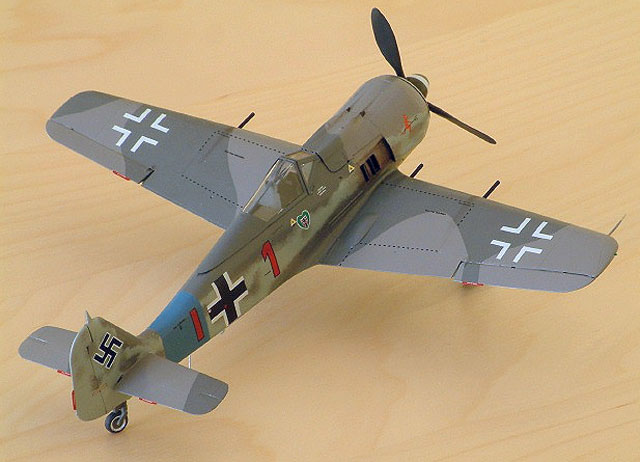
1/48 scale "closed up"
Focke-Wulf Fw 190 A-8
by Ken Stanton
|

|
|
Focke-Wulf Fw 190 A-8 |

Eduard's 1/48 scale Fw 190 A-8 is available online from
Squadron.com
I can echo a few of the feelings about this kit. It is not for the faint hearted or the inexperienced modeller. However, I also think that if you decide to make a 'closed-up' build then there are options available to overcome assembly and alignment issues to help get a good result. This is how my build progressed.
I would expect that if all the cowlings / access panels were left open it would be a much more straightforward prospect. I like the look of the FW190 airframe. For me, guided by the good reports on accuracy for the shape of this kit, having all the internal 'goodies' hidden away was not a waste.
Certainly, Eduard's notes regarding assembly of the wing spar and of the undercarriage are useful.
David Nickels' tip of removing the front corners of the cockpit tub not only works for improving vertical alignment but allows assembly AFTER the fuselage halves are joined. In fact, you can spring open the cockpit aperture and the tub snaps into the ledges below the top of the cockpit opening and there is no need for glue; and it will slide backwards and forwards a little!
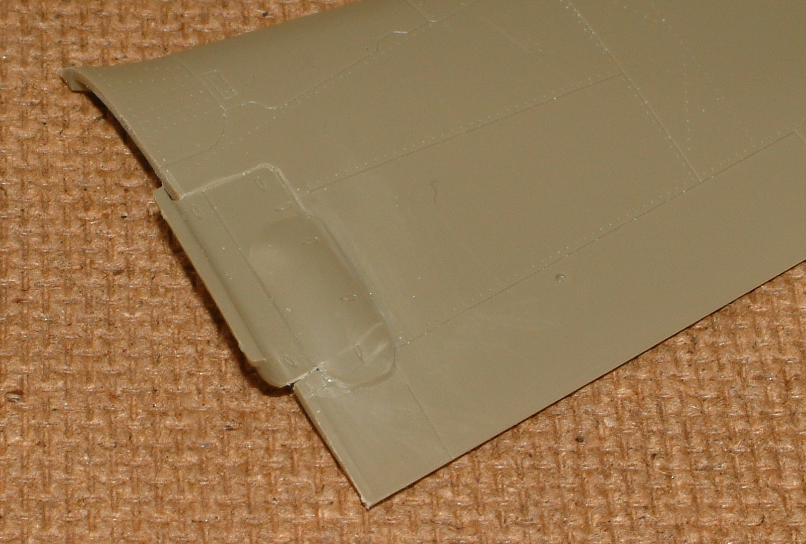
The wing root gun covers were attached to the wing upper halves after carefully filing the lower surfaces down to give a flush fit to the wing surface.
A test fit of the wing uppers to the fuselage indicated that no filler would be required at the wing roots.
Eduard’s tips recommend particular care when attaching the main spar and its abutment (K20) to the lower wing.
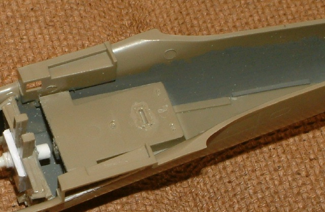
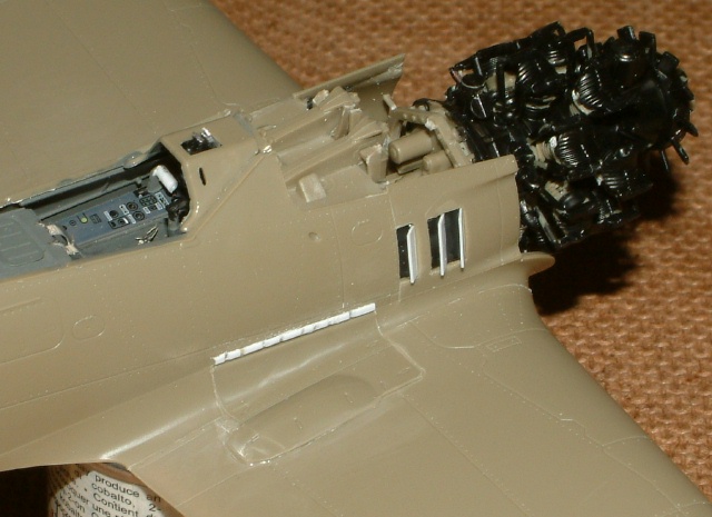
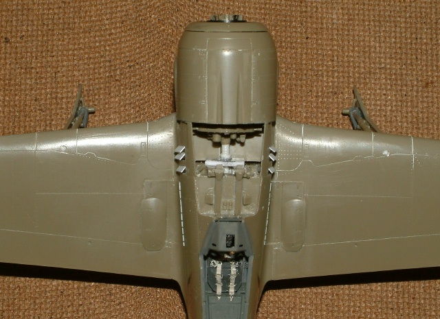
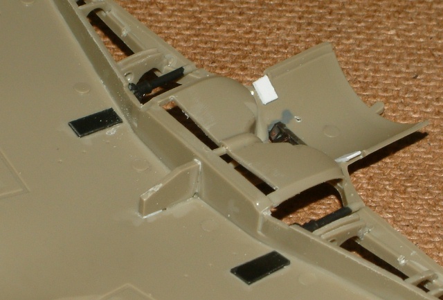
Small tabs (white plastic) were attached to the inside of the cowling joint. This was to aid alignment of the small ‘ears’ on the forward fuselage. Next time I would use thicker plastic for these tabs as, later, the liquid glue softened one and allowed the cowling to deflect it. The inboard wing cannon barrels were clipped off as they can be fitted after the wings are completed with the joint hidden inside the wing. There was also a risk that they could be snapped off during the wing assembly anyway! The main advantage is that cleaning up the wing leading edge becomes a lot easier. The black patches are to blank off the link chute openings.
The preassembled engine front cover unit was dry fitted after assembling the engine to its bearer and taping the lower wing assembly to the fuselage. The exhaust outlets were not very well aligned with the opening between the cowlings despite small strips of tape being used to secure the ends of the pipes to the template supplied in the kit whilst the glue set.
There was a marked 'down-thrust' appearance to the engine after the engine cowling was taped in place. Again, as this was a ‘closed up’ build, none of the engine mounting system would be visible. The mount was cut away and the engine removed.
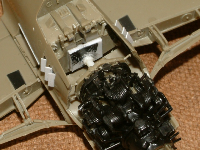
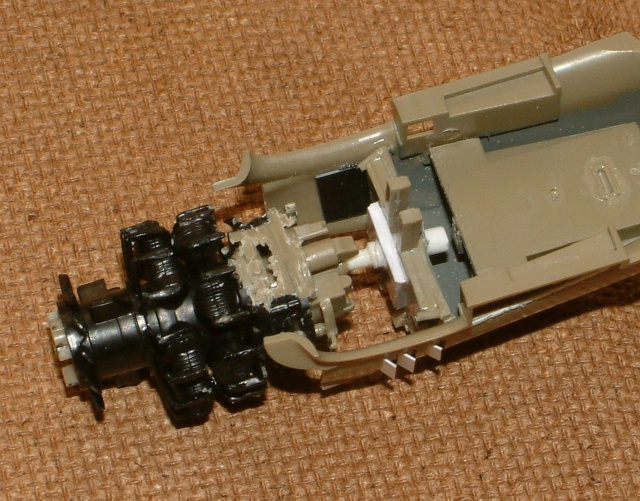
The front cockpit bulkhead (firewall) was drilled in the gap between the fuselage gun cartridge chutes and this was opened up to become a vertical slot to take a short length of plastic tube. A square of 1mm (0.04”) thick sheet was drilled to fit over the tube which, later, could be glued to the bulkhead for extra support. The rear of the engine unit was drilled to take a plastic rod that would fit into the tube.
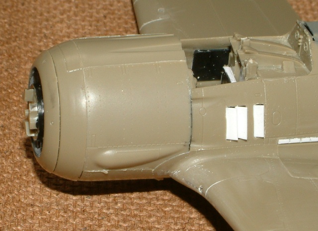
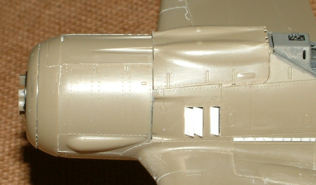
Rather than use the PE parts supplied in the kit, the vent apertures were opened up and plastic strip used for the vent flaps. The apertures were backed with black plastic to provide a surface for attachment of the flaps.
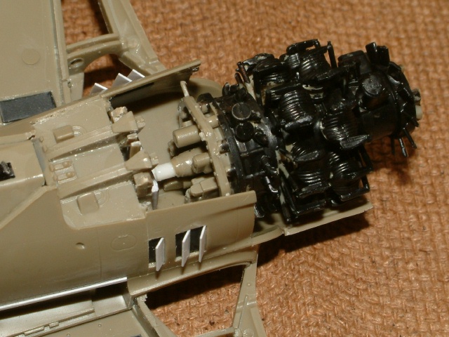
With the lower wing assembly taped to the fuselage the engine was slipped onto the tube and the preassembled engine cover test fitted. It was then a matter of finding what parts were fouling which and then reducing / removing them until the engine fan could be correctly aligned in the front cooler ring. The removal process was quite severe! The exhaust pipes were removed as part of this process.
None of the rear portion of the engine will be visible after assembly of the cowlings so a large amount of this was removed to ensure that nothing could prevent the rear of the engine from being pushed down. The front portion and the front faces of the cylinders are visible through the front of the cowling so both rows of cylinders were left untouched.
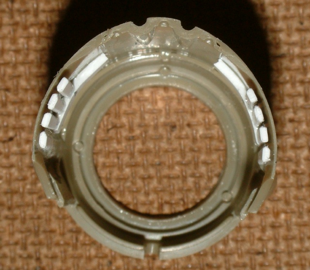
With the lower wing and cowling taped in place, and the engine located in the correct orientation, liquid poly was flooded into the tube, rod and around the plate to fix the engine in place and was left 24 hours to set. The cowling now dry-fitted well and the engine flexed up and down to accommodate any small change to the positioning of the cowlings. Later photographs show that the propeller backing plate now sits square to the cooler ring.
New exhaust stubs from were made from strip. As these would only be visible where the aperture is between the cowlings, they were attached to the inner face of the cowling starting about 10mm (0.4”) from the aft edge. When set they were cropped flush with the edge of the cowling. I did this a week before the Quickboost resin cowling was announced – honest!
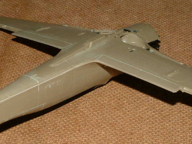
The wing upper halves were attached to the fuselage. Parts I14 or I15 were not used as they appeared to not serve any purpose with the gun hatches closed. One of the gun covers was a little low in height and left a gap under the fuselage hinge line. It is possible that this is intentional to facilitate assembly when the cover is fitted after the wings are attached and the etched steel hinge is intended to cover it up. I found these particular etched parts very difficult to keep straight and flat (my failing not the PE part!), so were replaced with plastic strip.
With the join allowed to dry overnight, the lower wing assembly was attached to the fuselage and upper wings. You can see that the rear of the lower fuselage was not a bad fit.
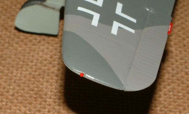
However, there was a gap at the root end of the wing leading edges. This was not a bad result as it was an easy task to fill with superglue and sand to shape. The upper and lower wing profiles were mismatched at the tips and the most of the detail for the navigation lights was lost. The navigation light recess was filed back into each wing tip and painted plastic rod used for the lights.
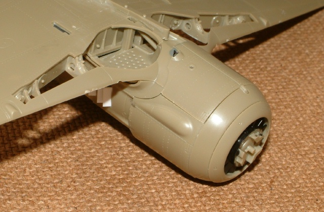
The engine cowling assembly sat forward a little creating a gap underneath, so the fuselage ahead of the louvres was carefully filed back to allow it to seat better. The fuselage gun mounting arms were removed to prevent fouling with the gun cover. The engine cowling assembly was then attached to the rest of the fuselage.
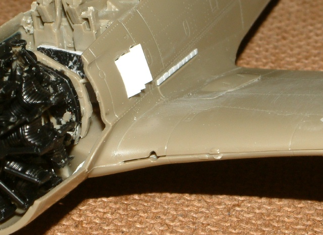
Although not relevant to a ‘closed-up’ build, I was a little nervous with respect to the strength of the joint between the top of the undercarriage legs and the underside of the upper wing. I can see how the joint is designed to control the location and the angle with the actuators (J30 and J37) controlling the angle lower down the strut and also the fore and aft positioning. I was just concerned about the ‘butt joint’ to the upper wing. A length of plastic rod was glued into the drilled undercarriage legs.

Then, using the locators in the undercarriage bay as a guide, the upper wing was drilled through. The undercarriage assemblies were then glued into place; finally running glue around the plastic rod where it protruded from the wing. You can see where the rods came through the wing after they were cut back and flushed off.
The geometry looks spot on; and this due to the design of the kit’s alignment method. The rods just give it more strength.
Having taken a little off the fuselage to position the front cowling, the upper gun cover required a little shortening to suit. This is just a dry fit.
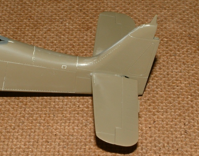
The tail-plane joints were a little loose so the tabs were packed out with a thin plastic shim on the underside of each to make them a snug fit and eliminate any droop.
The external fuel tank carrier, the ailerons and the rudder were then attached. The aileron hinge slots had to be opened out to allow them to seat properly. Because the wing tips had been re-profiled, the ailerons required similar treatment.
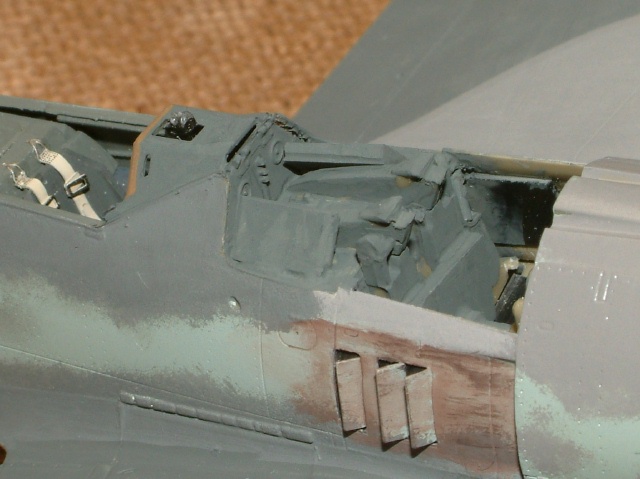
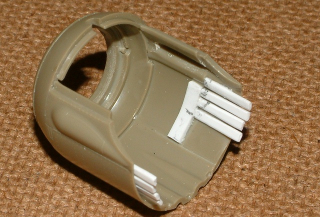
As the fuselage guns and their cover would be the last parts to be fitted there was the issue of fixing the gun cover when both it and the fuselage were fully painted and varnished. Two pieces of plastic card were attached to the gun platform positioned to leave 2 to 3 mm (approx 0.13”) gap to the inner faces of the gun cover.
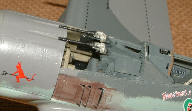
To ensure that no light coloured or white plastic would be visible through the gun barrel apertures this area was painted dark grey.
After the fuselage guns are fitted, a blob of 5 minute epoxy resin would be placed on each of these pads and the cover pressed into place; hopefully with no mess and a clean joint to the fuselage.
Painting,
Markings and Finishing Touches
|
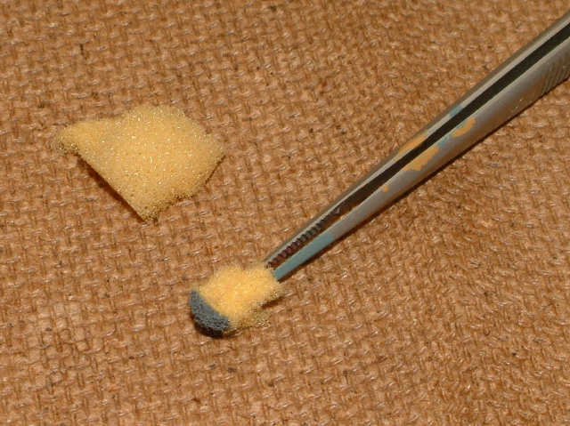
As I am a brush painter, the characteristic coarsely sprayed patterns are always a challenge. The soft edge to the paint was achieved using a piece of fine cell sponge held in a pair of locking tweezers.
The paints used were Humbrol and were mixed to make the RLM 74 / 75 / 76 shades shown in the instructions. The Eduard artwork shows RLM 74 to be quite green; I matched mine to the old Humbrol ‘Authentics’ Dünkelgraü.
The decals were a pleasure to use with no silvering and they took up most surface detail with just the application of a piece of kitchen towel soaked in hot water. Setting solution was only used for deep detail. The blue band was masked and painted. After gloss varnishing, decaling, and the application of matt varnish, the fuselage guns were fitted. It was surprising how much of each breech moulding had to be removed to make the gun cover fit. I would say that, for a ‘closed-up’ build, remove everything down level with the top of the barrel and just leave the minimum required to glue them in place.
It just remained to attach the fuselage gun cover, windshield and canopy plus the other ‘bits and pieces’ of exterior hardware. The wheels are an extraordinarily loose fit and it was down to super-glue to get them aligned to the mating face on the undercarriage leg.
If I were to do another of these (and I rather fancy the A5) I would probably find a way of not attaching part I21 (rear wall of upper gun compartment forward of the upper instrument cover) to the top of the fuselage as it would make an easier job of getting good alignment to the windshield and the rear of the fuselage gun cover by shimming it out if required.
The plan for fixing the gun cover with Araldite didn’t work quite as planned. I suspect the heat created by a large amount of curing adhesive caused the gun cover to ‘stress relieve’ and it pushed the restraining strips of tape away from the fuselage. The end result was not as good as the dry fit had indicated. Lesson learnt! Next time I’ll think about 1mm (0.04”) thick tabs attached to the inside lower edge of the gun cover and slots cut into the edge of the gun platform.
Still, I’m not too disappointed with the final result.
I managed to snap off the tail-wheel and so refitted it slightly turned.
The art work in the kit shows an aerial aft of the loop one and I cannot see any reference to it in the instructions. I used a section of guitar string and added it.
Next time I would also attach part J39 (cooling fan) to make the prop sit with one blade pointing directly downwards (personal preference – and the instructions show it that way too!).
I hope that this will be of interest and helps others to plan their Eduard ‘closed-up’ build.
Model, Images and Text
Copyright © 2008 by Ken Stanton
Page Created 21 January, 2008
Last Updated
21 January, 2008
Back to HyperScale
Main Page
|
 Home
| What's New |
Features |
Gallery |
Reviews |
Reference |
Forum |
Search
Home
| What's New |
Features |
Gallery |
Reviews |
Reference |
Forum |
Search