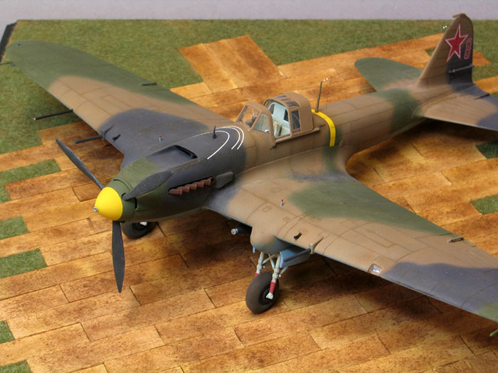
Accurate Miniatures' 1/48 scale
Il-2 Sturmovik
by Steven Budd
|
Ilyushin Il-2 Sturmovik |

Accurate Miniatures' 1/48 scale Il-2m3Sturmovik is avaiable online from Squadron.com
Often referred to as a ‘flying tank’ by virtue of its one and a half tons of armour plating, the Sturmovik is regarded by some air historians as having been a fine ground attack, close support weapon but a bit of a sitting duck when confronted with single engined fighters.
According to the latest Osprey book dealing with Sturmovik Guards Units this was not the case, for two principal reasons. Pilots learnt, through the hard experience of live combat missions that suddenly throttling back decelerated the Sturmo relatively quickly, forcing a pursuing German fighter to overshoot. Throttle open again, brisk reactions on the controls gave good opportunity to pump heavy cannon shells into the aggressor as he sailed past.
One pilot (whose name escapes me) shot down two Bf 109Fs in quick succession by this means. Another knocked down seven Germans, passing the ace mark comfortably and all while flying an aircraft not normally linked to aerial victories.
In the second case, shooting down one and a half tons of armour sometimes took more ammunition that a single fighter could deliver. Tales abound of Sturmo’s flying on with much of the fin shot away or large holes in the wings which continued to fly doggedly on, successfully delivered the pilot home (the gunner on two seat models was not usually so lucky – sitting the wrong side of all that protection). I particularly enjoy the story of the only encounter between a Japanese fighter and a single Sturmo. The gunner later commented that he was mesmerised into inaction by the beautiful flying display put up by the pilot of the Ki43 Falcon, who pitched and turned, emptying all his ammo at the Sturmo which flew on unperturbed until the gunner reported that he ‘grew bored and blew him to hell’. Charming.
Accurate Miniatures Sturmovik broke new ground in kit engineering when it was first released. Tamiya Magazine reported it as sufficiently complex to result in a model that was highly detailed but tricky to construct. This reputation has stuck and I’ve seen very few actually built up. Ironically, the normally sound advice for AM kits: ‘follow the instructions and don’t deviate’ will result in difficulties with the fit between the novel wing root arrangement and relationship of the lower wing section to the fuselage and the outer lower wing halves.
All this is easily avoided by a bit of tweaking with the recommended sequence.
The interior along the fuselage halves will look bare and relatively unadorned with no sign of the stringers and formers you’d normally find. The cockpit sides of the actual aircraft comprised hunks of the one and a half tons of armour plate the Sturmo lugged around the sky, so traditional reinforcement was redundant and unnecessary. The port side on the kit has a couple of big ejector pins in plain view of an open cockpit so need filling. As they also bisect moulded cables these need to be renewed, easily done from tiny sections of stretched sprue.
The cockpit is lovely. The kit guide recommends a colour similar to RLM02 but my research suggested ALG-5 Metal Use Primer was a fair choice so this was ordered in from White Ensign models. The large fuel cell immediately behind the pilot was sprayed with X1 Tamiya gloss black before masking off the metal straps and dusting Alclad II Aluminium over them. The moulded cable was hand painted with Xtracolour Gunmetal before satin varnish from Xtracolour was misted over.
The fuselage can be closed up before installing the pit from below. I varied the sequence by joining the nose halves to their respective rear sections which allows the joint to be manipulated for best fit. I was glad I did this as they were slightly short on width that I left ‘as is’ to become a gap in the top seam (when the halves were later joined) which would be more easily resolved.
Breaking away again from the AM build sequence I glued each top wing half into their root positions. The plastic joining face on the starboard side is inch perfect and a flush fit but the joint introduces a little extra unwanted dihedral that needs to be lost. Simply sanding the lower part of the joint face on the wing half lets it drop enough to cure.
On the port side it is a different story. The wing joint face is too thick by a small amount – simply sand to reduce until the flush fit matches the other side. Dihedral also needs to be knocked off as per the other wing. Fitting the upper wings in this way makes the wing root join easy and controllable and very tight.
The two sub-assemblies were then joined as the tail wheel unit was added and the joints cleaned up with CA and Mr Surfacer 500. The lower wing section had its spars attached to set the dihedral and these parts also contain provision for mounting the completed cockpit assembly. Having departed from the instructions to some degree already I decided that it may be preferable to attempt to test fit the cockpit into the fuselage without installing it onto the lower wing. The instructions advise that the cockpit will ‘snap into place’. Maybe it is just me but I have an automatic reticence towards forcing anything into position. There was no option however and it seemed that with the degree of force being required, that the finished subassembly would fly apart if I pressed any harder. It truly snapped into position with an audible click.
It was immediately clear that something wasn’t quite right as the fuel cell sat noticeably off centre when viewed from above. Eventually it was apparent that the cause was the displacement of the elevator actuating rod, which had slipped out from between the cut-outs in the pilot’s armour and rear bulkhead. I hadn’t planned for removal of the cockpit and with even more trepidation forced it out. A repeat test fit simply duplicated the problem again so out came the pit and the actuating rod was CA’d into the cut-outs before having its surplus length, from the rear bulkhead backwards cut off. The part itself is moulded primarily for the two seat version and needs the extra length as it would otherwise be visible in the rear station. Once cut down and glued into position, the cockpit fitted perfectly.
Having now wandered away from the established assembly sequence, it was necessary to remove all the alignment pins in order to fit the wing lower section. Once installed, the lower wing outers were run in and their rocket rails fitted.
The instrument dials were carefully masked with Copydex craft rubber cement under the 3.5 mag Optivisor before the panel itself was painted a very light grey in accordance with advice on the web site ‘Modelling the aircraft of the VVS’ before the decal provided in the kit was added to the rear face. The rear of the panel was sealed with varnish and left to cure before it was later glued in position in the cockpit. The gun sight, being mounted on a long rod was left out until final assembly, so that the cockpit could be safely masked.
The horizontal stabilizers were glued and all of the Fletner rods were added to the various flying surfaces. AM provide ample warning in their instructions about the vulnerability of the fin counterweight which I duly ignored as I broke it off three times in succession while handling the model, until forced to acknowledge that it would have to stay off until after final assembly. I succeeded in also repeatedly breaking the counterweights fitted to the extremities of either wing. On reflection, it would be possible to protect these during construction by taping card over them but I remain unconvinced that they wouldn’t become casualties once paint began to be applied.
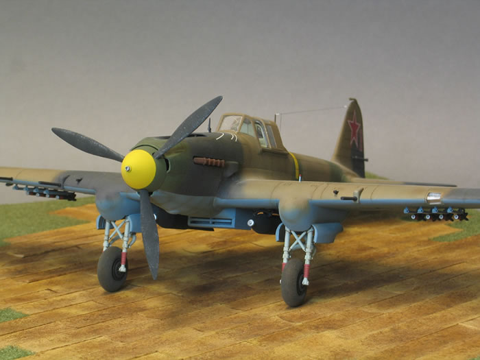
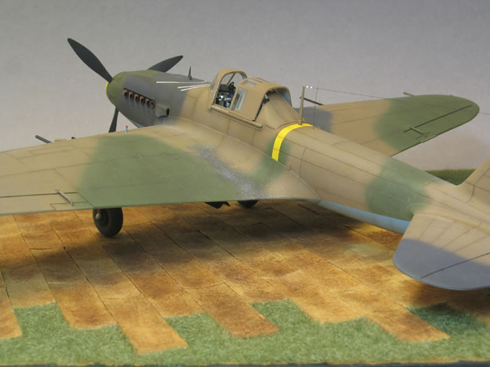
The nacelles were fitted and faired in with Superfine White Milliput, smoothed perfectly with a wet finger, before all the remaining ancillaries in the kit such as the undercarriage, bombs and so on were cleaned up, painted and finished ready for the final glue fest.
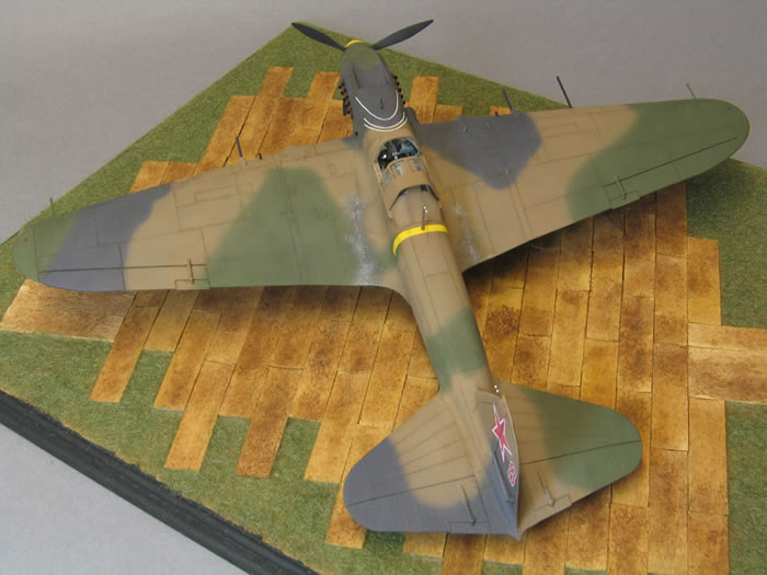
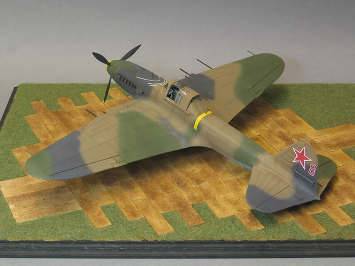
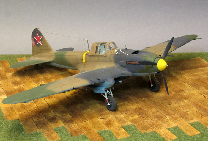
With the cockpit masked off, a custom mix of Tamiya acrylics XF23 Light Blue with a few drops of XF8 Flat Blue made up the fairly vivid blue seen on the under services of early war ‘Cementers’ (the German nickname for the Sturmovik). This was weathered with the Chris Wauchop mix of Tamiya Red Brown and Nato Black in the 10% paint, 90% thinners ratio.
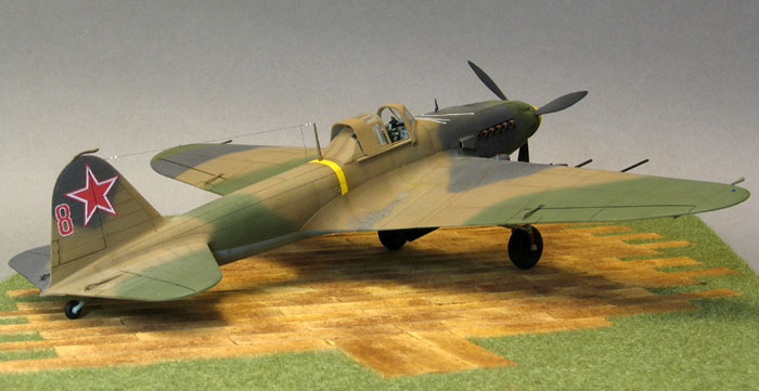
Following the standard MO of lightest top colour first, Gunze Brown acrylic H310 was run on, having first masked of the demarcation edges as per the painting guide. Sticking with Gunze, Green H303 and Extra Dark Sea Grey H333 were sprayed free hand having first marked out the appropriate areas lightly in pencil. Pointing the airbrush ‘into’ the area being sprayed at a 45 degree angle gives a tight feather along the edge of the new colour.
Some restrained weathering was applied to the green and gray by way of Humbrol enamels. Several different shades of green and gray were streaked and dabbed and dry brushed in succession until the finish was moderately broken up. Applying enamels over acrylics ensured no conflict between the colours. Once this had cured the surface was protected by spraying it with Tamiya clear gloss and several custom oil washes in shades of brown and greenish brown were run into the panel lines. The whole ensemble was finished off with the ubiquitous Chris Wauchop mix being run along some panels. The edges of some lines were masked off and the shade overlapped into the tape (vertical panels were shaded ‘tail side’, horizontal lines received shading on the lower edge).
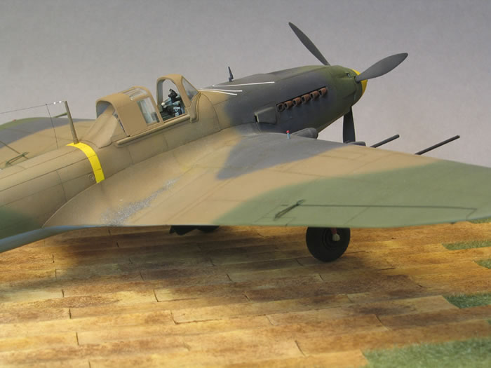
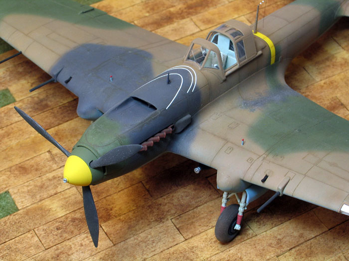
The exhausts were hollowed out using a grinding bit on my motor tool before being painted and weathered with Tamiya Red Brown and sympathetic pastel shades slopped on with an old brush and sealed with matt varnish. The drilled and hollowed interiors were given an oily black finish before installing them through the front of the fuselage.
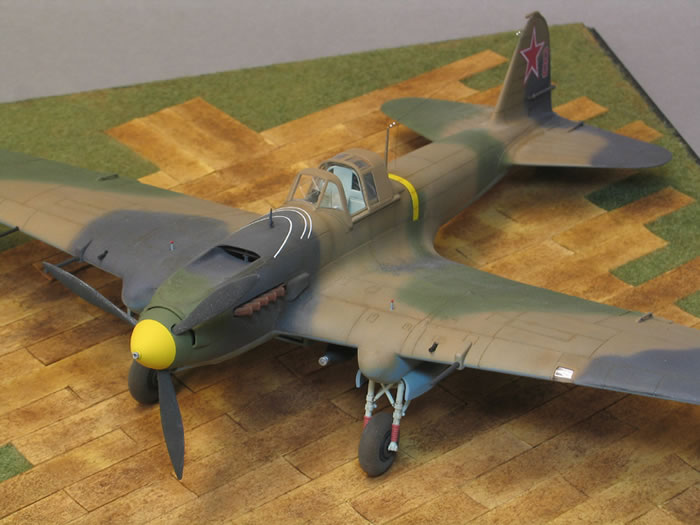
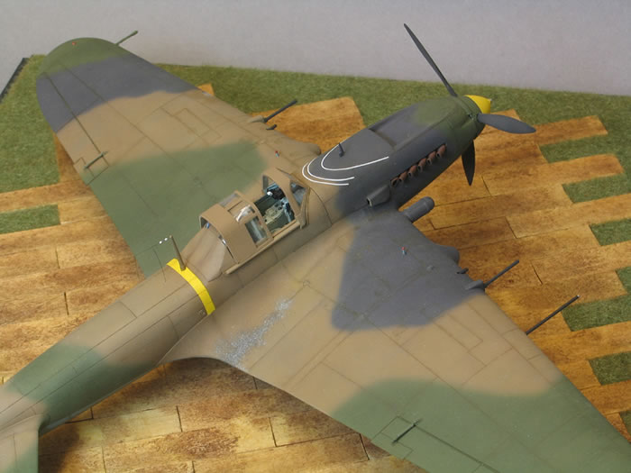
The prop was painted black and the hub sprayed in the camo green. Once cured the hub was masked with Parafilm M and a new blade run round the groove dividing the front and rear sections (this had earlier been defined and deepened with a scribing tool to give a positive guide for the blade). The Parafilm M was removed from the front of the hub and Tamiya flat white was over sprayed to kill the green. Tamiya flat yellow completed the job and with the rear masking removed was sealed with more flat varnish. The Hucks starter was detail painted with Xtracolour Gunmetal by hand.
The rear fuselage yellow band was masked and sprayed as the radio mast had been added earlier in the build for strength. The same Tamiya white was used to kill the brown before adding the yellow.
Parafilm M also dealt with the clear parts which were prepped with ALG-5 and then topped with the brown and sealed with matt varnish.
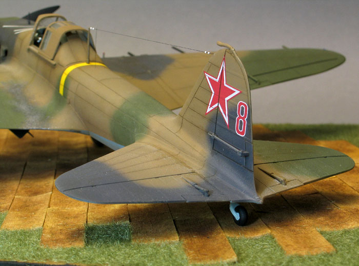
The few decals refused to respond to any setting solutions despite my entire armoury being brought to bear, until they were physically attacked with a sharp blade along the relevant panel lines, at which point they finally conformed and folded into the recesses.
The bombs and rockets were CA’d in along with the cannons, pitot and undercart indicators on the upper wing. The radio aerial was CA’d to the top of the mast and a little Gunze brush painted over ‘wet’ to conceal the bond. I had earlier drilled a very narrow hole using a .30 drill bit in the fin to simulate the fitting used by the Sturmovik. The line was passed through the hole and brought back on itself to cross the line some 3mm in front of the fin. CA locked the arrangement in place and the excess was (very carefully!) removed with my flush cut sprue nippers. A short second line was threaded through a hole drilled in the fuselage top decking and overlapped with CA to the main line. Another very careful snip and it was done. Tamiya Nato Black was applied to the line with a pre-damped brush (to increase ease of flow) to give it some ‘presence’.
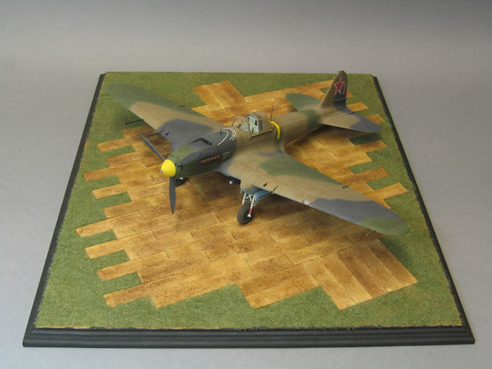
In my opinion, the Accurate Miniatures Sturmovik has a reputation for being a difficult build amongst modellers that it doesn’t deserve. A few small deviations from the recommended assembly sequence cancel out the problems reported when the kit was first released and result in a build that is a genuine pleasure to complete.
There is a lot of modelling in the box so pace yourself and expect it to take longer than your average single engine kit.
The base was a real, ‘Saturday night’ last minute special. I had amassed a collection of unfinished MDF bases from visits to various model shows. A suitable size was selected and the edges painted with Humbrol enamel black. The Luftwaffe planking was easily cut from Basswood veneer and wood glued to the base. A selection of custom mixed oil washes, in brown and blackish brown were freely slopped over the wood and force dried with a hair dryer. Woodland Scenics Static Grass was heaped over the exposed bits previously covered in their own brand Scenic Glue that dries matt and clear. The grass was dabbed down by finger pressure to indent it into the glue and ensure a matted appearance. My Sturmo now sits on the recently abandoned Luftwaffe temporary hardstand, the accursed Bosch having fled before the irresistible might of the Red Tide. At least that’s the way I see it.
Reference
http://vvs.hobbyvista.com/index1.php (Modelling the aircraft of the VVS)
Model, Images and
Text Copyright © 2008 by Steven Budd
Page Created 24 June, 2008
Last Updated
24 June, 2008
Back to HyperScale
Main Page |
 Home
| What's New |
Features |
Gallery |
Reviews |
Reference |
Forum |
Search
Home
| What's New |
Features |
Gallery |
Reviews |
Reference |
Forum |
Search