|
Revell 1/32 scale conversion
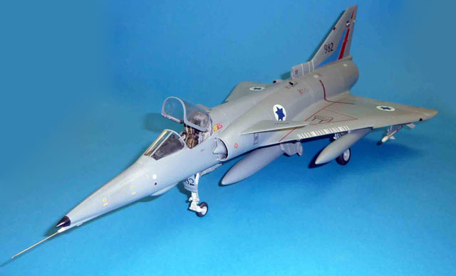
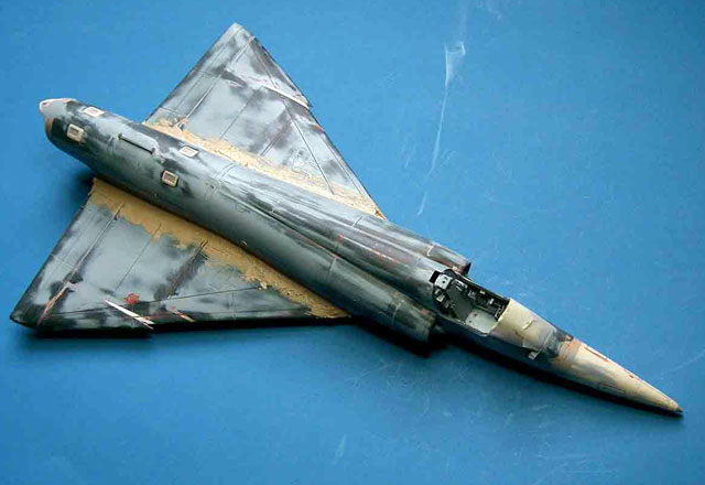
IAI Kfir
by
Frank Mitchell
|
IAI Kfir |

HyperScale is proudly supported by Squadron.com
I decided to write up this model only because I learned at the ’08 Nationals that Isradecals is preparing a 1/32 conversion kit for the Kfir and I wanted to get full credit for triggering this welcome event.
The starting point was, of course, the 1/32 Revell Mirage, a kit that was first issued in 1973 (Yes, I was building even then; it is Hell to get old). It was considered a pretty nice kit back then, and has been re-released a number of times in various configurations and markings.
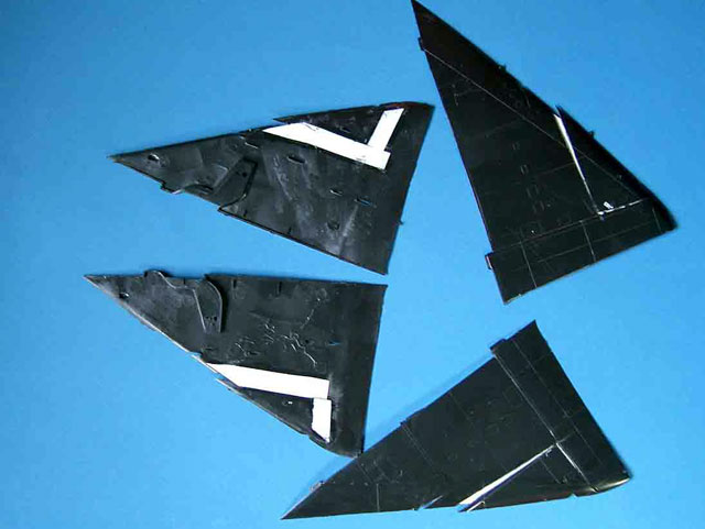
The kit definitely shows its age; there is a fair amount of flash, a combination of scribed and raised panel lines, not much of an interior, very hard black plastic, etc., etc. The external shape is reasonably accurate except for a few things that can be fiddly to fix. Perhaps the two main ones are 1) A wing that is much too thin from about mid-span to the fuselage (there is no way that the main landing gear would fit into that shallow space), and 2) The shape of the fuselage/canopy area needs help. Both issues required some work, but both are well within the capability of any reasonably experienced modeler.
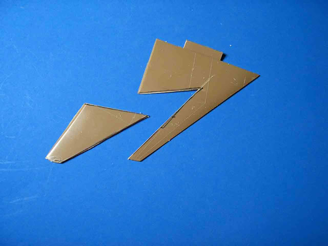
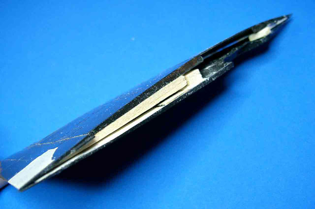
The wings were the first project. After taping the wing halves together, the first step was to wedge a short ¼ inch thick scrap of balsa between the upper and lower wings at the roots, just behind the molded-in wheel wells. From the front, this produces a much more accurate, thickened appearance. To strengthen and fine-tune the airfoil shape, additional pieces of balsa were sanded and placed in the opening as necessary. When I was happy with the appearance, the balsa bits were glued to the interior of the upper surface, the wings were separated and the tops of the kit wheel wells were removed, leaving in place a small area to mount the main landing gear. The wells were boxed in with styrene sheet, trying to make sure that the wing and fuselage sections of the wells matched as closely as possible. Detailing was added until I got tired.
To produce the dogtooth extension on wing leading edges, the leading edges were cut, brought forward, and superglued into place. All the resulting gaps were filled with styrene and two-part epoxy, then sanded to final shape.
I found some information on the Internet that suggested that the kit wings were too short in chord. However, I was not able to confirm that, so I elected not to create more wing problems and left them alone.
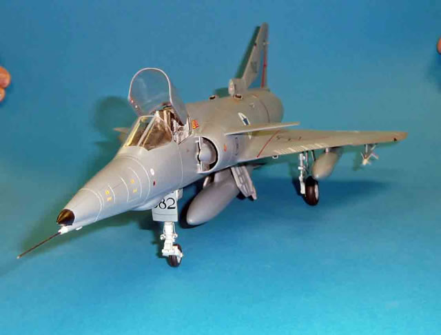
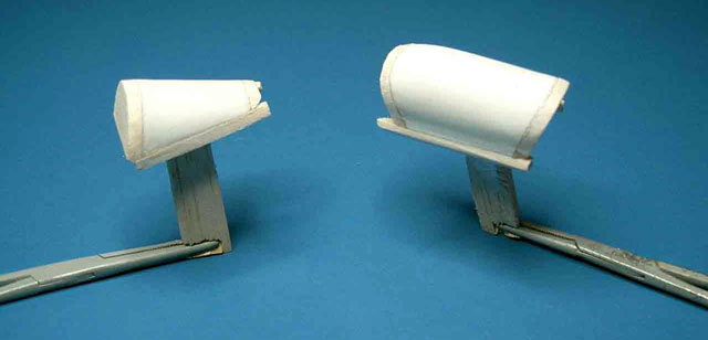
The second most obvious problem with the kit is that, from the front view, the kit has the canopy, windscreen, and matching fuselage fairing meeting the fuselage in a straight, vertical line. In fact, all three are narrower than the fuselage with a flare that runs along the bottom of canopy. This is quite noticeable in pictures. The first modification was making thin cuts with a razor saw a short distance above the bottom of the canopy opening and straight back along the canopy fairing for about three inches. This allowed the fairing opening to be pinched together and set in place by careful bending of the plastic and the addition of stretched sprue along the inner part of the cut line. Small pieces of scrap styrene were added to the joint and the area sanded to produce the correct flare from the fairing to the fuselage. All this hopefully makes more sense in the photos.
The windscreen itself does not have a flare, so the top edge of the area of the fuselage where it fits was sanded to the correct shape. New clear parts were made from plaster of Paris molds which had the flares sanded into the proper places. The new clear parts were made of vinyl by the heat-and-smash technique. Using vinyl for the new windscreen allowed it to be squeezed and glued into place, giving the proper amount of flare to that area.
With these two problems on the way to being solved, I began to work with the CAM conversion kit.
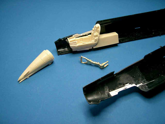
Overall, the CAM kit is reasonably good, although some changes were necessary. The tub looked good and fit together with only the usual amount of sanding and grinding. Mild modifications had to be made to the back of the tub to fit the now-flared canopy shape, and a new mounting for the CAM-supplied brass nose gear was made up from styrene. The nose of the CAM kit is also too short by, as near as I could figure, about ½”, so that was added by means of a balsa plug. The top of the instrument panel was too tall, so it was separated from the bottom section and lowered so that it stuck into the windscreen the proper distance. Changes were also made to convert the panel to a C2 Kfir, rather than the C7, which the CAM kit provides. One trick that comes in handy is to superglue a piece of very thin (0.005) styrene onto the back of the resin instrument panel. This allows the holes for the instruments to be drilled without the whole thing falling apart. The change in the height of the panel also meant that a new glare shield had to be formed from scrap styrene, and details were added where necessary. New side panels were made up due to the changes I had made to the shape of the fuselage.
The CAM seat was good, so was just detailed and painted as necessary.
The CAM kit supplies several vents that are not on the Mirage, and these were added by cutting appropriate holes in the fuselage .
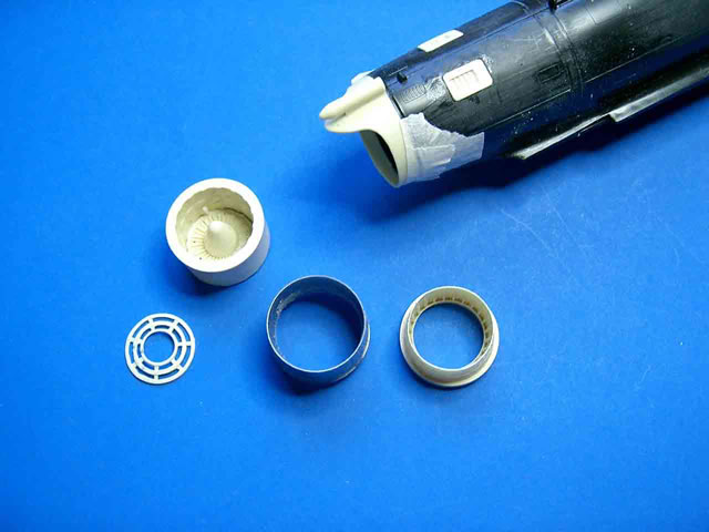
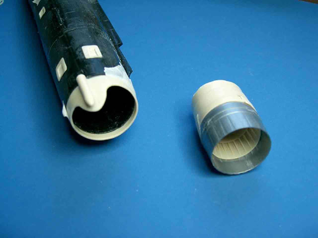
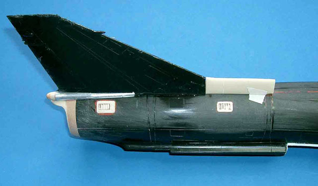
After looking at enough pictures in the excellent Isradecals book on the Kfir, I felt that the engine exhaust nozzle burner can was too small in diameter and to fix that, I robbed a 1/32nd F-104 kit which had one that was much closer to the appropriate shape. That required a bit of change in the way the engine was mounted in the fuselage, but nothing too major. While at the rear end of the fuselage, the parachute housing was also enlarged since the kit part was much too small in diameter. This was done with a 6mm piece of aluminum tubing and a cone-shaped part turned from basswood.
The kit intakes fit well, but some filling is required around the splitter plate/fuselage/intake seam.
The gun troughs in the bottom of the kit intakes are only vaguely represented by a shallow groove. To more accurately portray them, a piece of 1/8th inch balsa was rounded off on one end and the two pieces of styrene were heat-and-smashed over that edge. These were then superglued into the grooves which had been enlarged and deepened. Once everything had dried, the excess was sanded off, the remaining defects filled with putty, an two barrels added.
The CAM canards were shaped well, but were warped. Since I have not had good luck straightening resin pieces (they straighten fine, but then revert after several weeks or months; I must doing something wrong); therefore, a new set was cut out of some scrap Revell F-4 Phantom horizontal stabilizers.
The vertical tail needed the CAM- supplied extension of the Kfir , and the rear warning devices near the tip were also added.
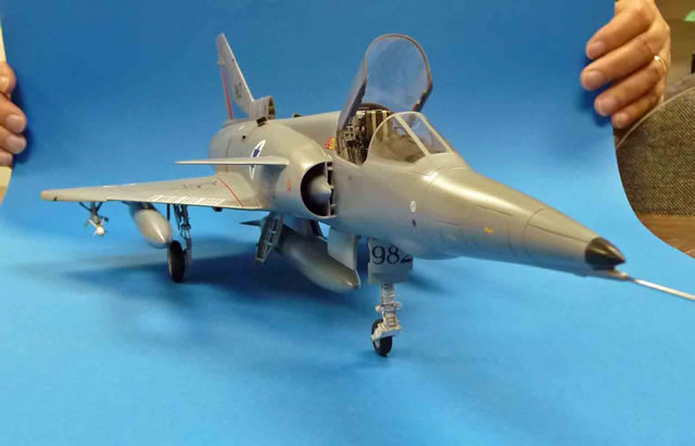
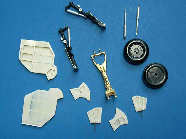
The main landing gear were rather heavily modified Revell pieces, since the CAM brass pieces were considerably undersized. The Revell main gear wheel were widened somewhat. The brass nose gear was used after having the landing lights and some additional detailing added. All the gear needed new struts and retraction cylinders, but the CAM gear doors were used with just some cleaning up.
I made up some Python missiles to put on the wings, and used the CAM centerline tank.
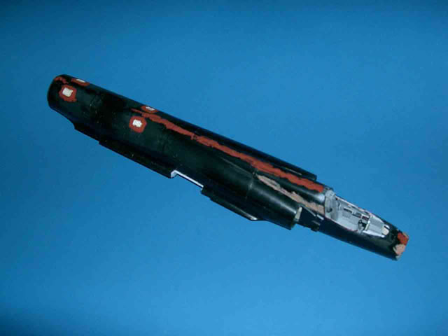
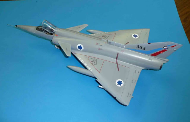
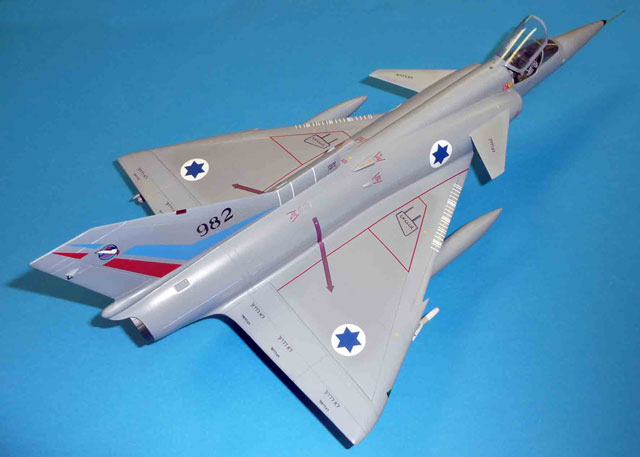
The paint was Gunze two-tone gray as featured in the Isradecals book.
The decals are a bit of a story in themselves, and this is one area where I do want thanks. In order to get all the markings, I used some ¼” scale Kfir Isradecals (a trick I have used for years, and am constantly amazed how few ever notice), some 32nd decals from the same company that were intended for the A-4, some solid color sheets for the tail sweeps, a few small things from the scrapbox, and finally, I hereby admit that I blew up a couple from the ¼” set, a move that I consider only partially successful and which I do not recommend.
I may even consider re-paint when a decent set of decals appear (but maybe not).
After my Kfir was finished, I realized that I missed a couple of things, but I have been too lazy to go back and add things. The reader can determine for himself what I missed...
In all, it was a lot of work, but it was done in several stages, which lessens the burn-out.
Model and
Text and Images Copyright © 2008 by Frank Mitchell
Page Created 26 September, 2008
Last Updated
26 September, 2008
Back to HyperScale
Main Page |
 Home
| What's New |
Features |
Gallery |
Reviews |
Reference |
Forum |
Search
Home
| What's New |
Features |
Gallery |
Reviews |
Reference |
Forum |
Search