Lindberg's 1/48 scale
Fairey Flycatcher
by Bill Bowe
|
|
Fairey Flycatcher |

HyperScale is proudly supported by Squadron
Background
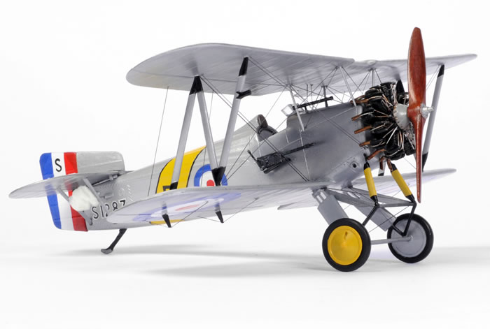
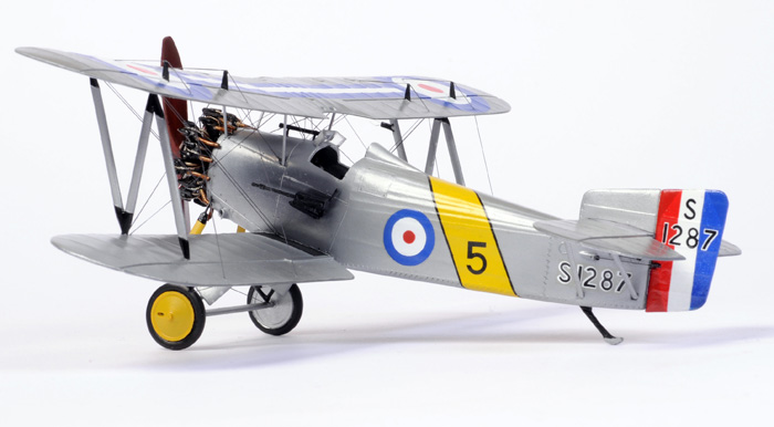
The Fairey Flycatcher served from 1923 to 1935 with the Fleet Air Arm in the Home, Mediterranean, East Indies and China fleets.
It was a decidedly odd looking aircraft with it's 'broken' back yet was superbly responsive and easy to fly. Supposedly it did not actually need arrester assistance when landing on a carrier deck as it’s own brakes, full span flaps, variable incidence tail planes and sprung landing gear providing a short enough (if somewhat nerve-wracking) landing run.
History shows that it was actually one of the most important, if least known aircraft in naval aviation. It was the first custom designed carrier based aircraft. A Flycatcher was the first aircraft to be tested with transverse arrester wires, using an arrestor hook, in 1930 and it was the last aircraft to be able to operate slip flights from the forward hangar below the main deck of Royal Navy carriers as it was the last RN carrier aircraft able to take-off without the aid of a catapult. Flycatchers were capable of being flown from platforms on the turrets of warships, and were used in this way until about 1932. (thank you Mr Google in general and www.aeroflight.co.uk in particular).
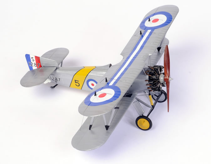
Being from the between wars period. it was also a colourful and interesting subject.
Lindberg's 1/48 Fairey Flycatcher
The mould’s for this kit were originally produced by Inpact in the early 1960s as part of a series of between war British fighters including the Fury, Gladiator and Bulldog. Judged against modern kits there’s some chunky detail, flash, ejection pin marks etc. Their shape however is very good, they fit well and they have a lovely representation of fabric covering.
The moulds were re-used by Lifelike, Pyro and Lindberg with mine being the Lindberg boxing.
The plastic is easy to work and not brittle at all.
Decals are probably the weakest part. More on these later.
Fuselage
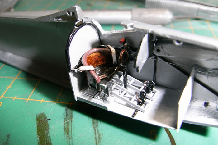
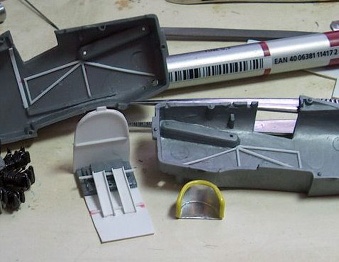
I started with the cockpit, which I scratch built apart from the instrument panel and control column based on the one cutaway drawing that I had for reference. I built the seat from thin metal sheet and electrical wire insulation with a putty seat cushion.
After putting it all together I found that the original seat shape was probably correct. I thought mine looked better though and it was too late by then to take the fuselage apart.
Instruments and spurious cockpit placards are from Mike West’s fantastic instrument and placard decal sheets..
Cockpit framing, bulkheads, rudder pedals etc. are plastic rod, plastic sheet, wire etc. Gun ammunition feeds are cut up roofing plumbers lead sheet (probably not lead) and the throttle quadrant is leftover from an ICM Spitfire kit.
Seatbelts are painted/ washed masking tape with bent fine wire hardware.
Painting was simply a household silver spray paint bomb and Tamiya gloss black acrylic with citadel brown inks for the finish on the seat and control column handle.
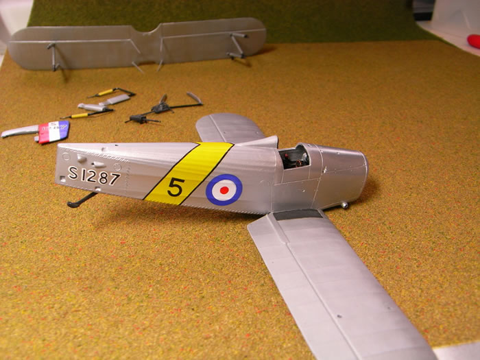
Construction then proceeded fairly normally with a bit of putty and sanding needed to get rid of the seams. I also rescribed the raised panel lines on the cowl. The scribing turned out a bit heavy but not too bad.
Top Wing/ Cabane Struts
Next challenge was the cabane struts. These were moulded very heavily and as left and right one piece assemblies fitting loosely into the cowling. To get around this I glued the strut base in after cutting off the struts and putty sand, putty sand, prime, putty, sand, prime, putty sand, prime later had a nice smooth cowling. For priming I use Tamiya fine primer spray bombs and they work very well.
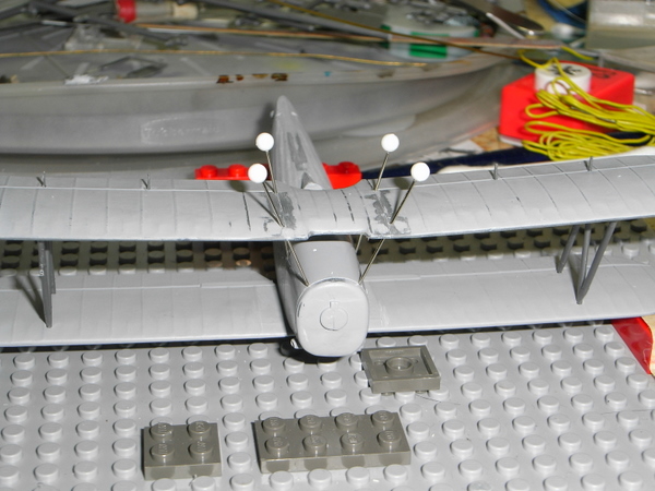
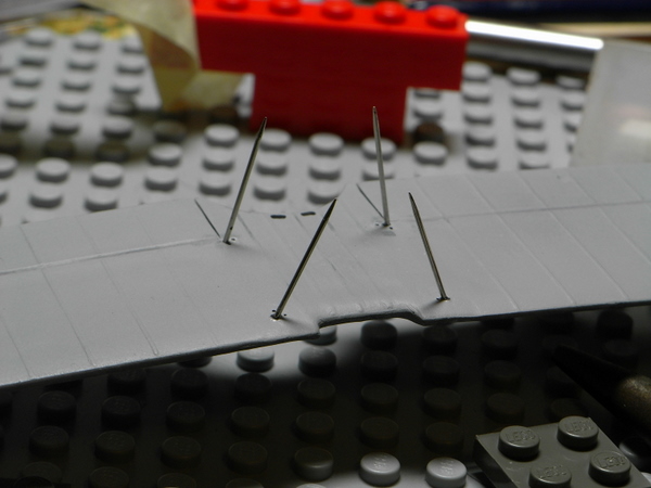
I then drilled holes at appropriate angles into the cowl to mount the sewing pins which would form the cabane struts and similar holes through the top wing. Following this I glued the main struts to the top wing, blocked it into place with that wonderful invention Lego and pushed the pins through and aligned everything by eye.
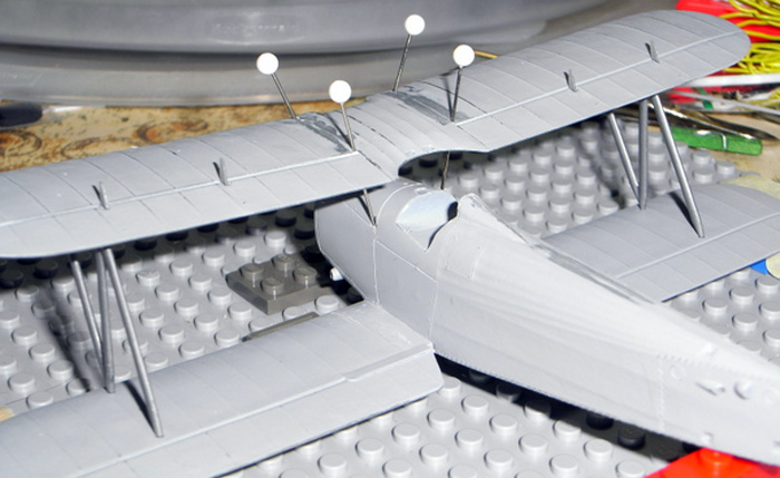
The next step was to leave everything blocked up and, one by one, remove then cut the individual pins down to size, replace them and then super glue them into the top wing. Followed by putty, sand, putty, sand, prime etc. This left me with a top wing with all struts attached that, hopefully, I could just pop this into place after painting and decaling.
 Paint was Talon Acrylics from Hawkeye which went on very easily from my Aztec airbrush. SNJ powder was used to polish up the cowling (also from Hawkeye). Paint was Talon Acrylics from Hawkeye which went on very easily from my Aztec airbrush. SNJ powder was used to polish up the cowling (also from Hawkeye).
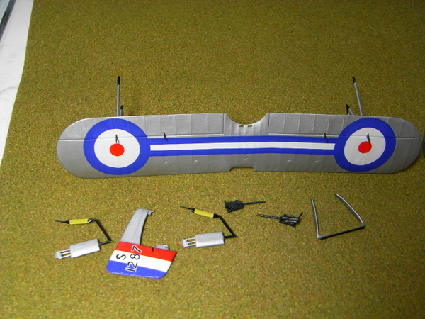
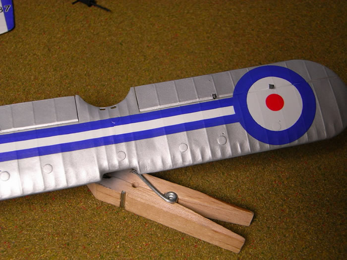
Decals on the other hand weren’t quite so straightforward. The Aeroclub decals that I got as a bonus with the kit were the right colour but the red centres of all the roundels were out of register and far too large. Also these decals are very thick. The kit decals (actually rub on transfers) had completely the wrong shade of blue.
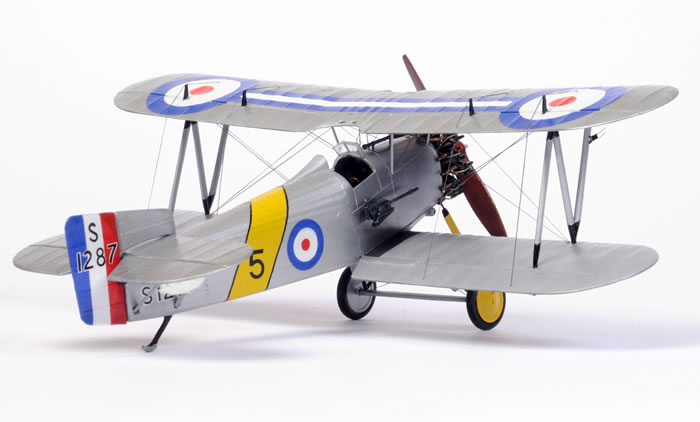
The markings on the build are therefore a bit of a mish-mash of Aeroclub and other kits. On the main wing roundels the blue circles and connecting line are from the Aeroclub sheet with the centres cut out using a compass cutter. The whites of the roundels are backing decals from a Tamiya Spitfire I kit and the red centres are from an Airfix F.22 Seafire kit. Quite surprisingly all this actually sucked down to the surface really well using Micro set/ sol and Gunze Mr Softener. This is especially obvious over the round inspection hatches on the top wing (punched from thin aluminium sheet). There was some cracking when the decals dried which I touched up with oil paint. I find oil paint works best for these touch ups as it can be worked for some time and the edges feather into the surface far better than enamel or acrylic. The fuselage roundels are from a Roden Bristol Fighter kit, again with centres from the F.22 Seafire kit (I think from memory). Tail and fuselage band are from Aeroclub. In hindsight I should have just painted all the red, white and blue.
All the rigging holes were drilled at this stage also.
Fiddly bits were built at this stage including the undercarriage and guns. Most of the mounting struts on the undercarriage were replaced with pins and wire. The guns were basically scratch built using just the kit gun body with cocking handles and mounting details from card, rod etc. and barrels from the Trumpeter Wellingtons 1/48 ventral dustbin turret (when I build this kit I’m not going to include this turret).
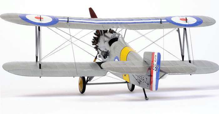
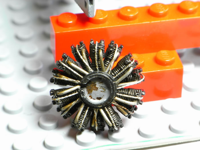
The engine used the kit crankcase and cylinders. Holes were drilled for the pushrods, ignition wires, exhaust and inlet pipes. Pushrods are from straightened beading wire (stretch it between 2 pairs of pliers and it remains perfectly straight), ignition wires from thin wire and inlet pipes from solder painted with citadel inks (these inks are very useful).
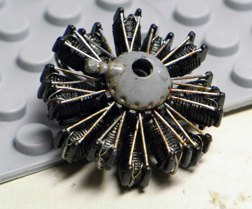
The exhaust pipes were built and added at the very end of the build.
Guns, undercarriage, engine and tail were glued on then, using a clothes peg to slightly spread the front set of sewing pins/ cabane struts the top wing simply dropped and snapped into place. I was more than surprised as I’d been dreading this moment.
Rigging went smoothly using Aeroclub black lycra thread (worlds best rigging material). My rigging method is as follows. Before putting the top wing in place I plan the rigging so that I can work (as a general rule) from the fuselage out to the wingtip and from top wing to bottom wing. Then I glue one end of each rigging wire into the receiving hole drilled earlier. Once the top wing is attached I attach the other end of the rigging line by line. I cut an individual run to about 2/3rds of the gap it needs to cover, place a small drop of superglue into the hole to receive the unattached end then stretch the line to that hole using fine tweezers. Waved some superglue accelerator over the spot, hold it for 15 seconds and hope it holds. All this is made possible by mounting the model securely on a base board with lego, elastic bands, tape etc. If you don’t mount it like this you run out of hands.
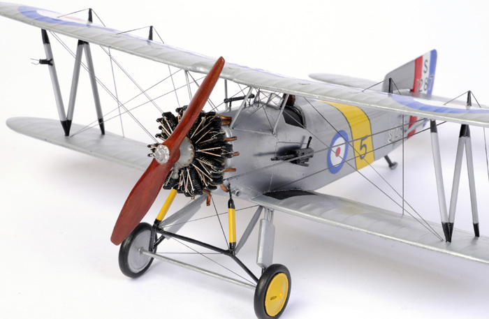
Following the rigging, each of the engine exhaust pipes was made from a piece of electrical wire individually bent to shape with the wire pushed back through the insulation. Using the insulation like this means that the pushed through wire can be used as a locating pin to glue the exhaust to the cylinders, while at the other end the insulation forms a nice hollow exhaust pipe.
Prop was painted with a light tan acrylic base followed by oil paint.
Weathering was effectively non-existent as these planes would have been very well looked after being the pride of the peacetime Royal Navy (and I was lazy and working to a deadline).
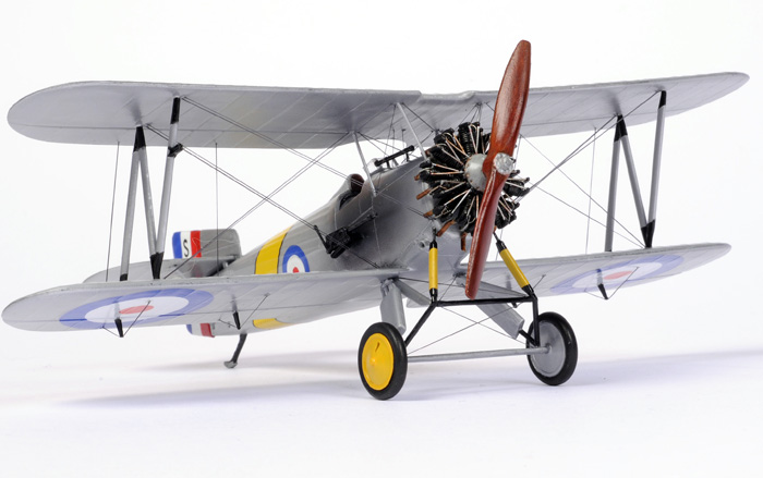
Lindberg's 1/48 scale Fairey Flycatcher is a lovely model. Nobody should be scared off by the age of these old Lindberg kits. Unusual subjects which you can add as much or as little detail to as you want and still have a good model.
I got this model completed just in time for ScaleACT (the ACT Scale Modellers Society yearly show) and was lucky enough for it to place third in its category.
Even better, Brett Green was taking photos there which led to this build review. I’ve never sent something like this in before so hope you enjoyed it. I did.
Thanks also to Brett for this website and the support he provides for the hobby and to all the people on this and similar sites who give great advice and critique.
Model, Construction Photos and Text Copyright and 2008 by Bill Bowe
Completed Model Images Copyright ©
2008 by Brett Green
Page Created 8 June, 2008
Last Updated
9 June, 2008
Back to
HyperScale Main Page |
 Home
| What's New | Features | Gallery | Reviews | Reference | Resource Guides | Forum |
Home
| What's New | Features | Gallery | Reviews | Reference | Resource Guides | Forum |