Roden's 1/32 scale
Albatros D.III
by
Bruce Salmon
|
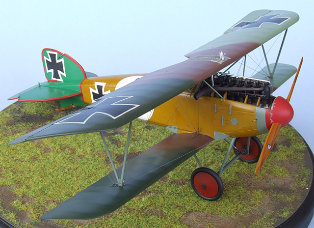
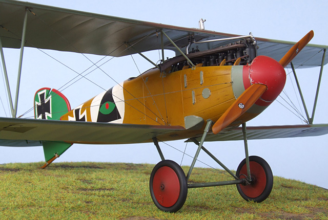
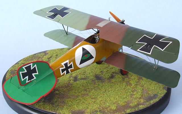
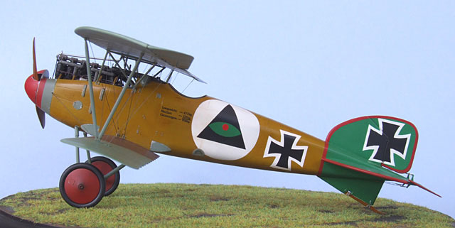
Albatros D.III 1/32
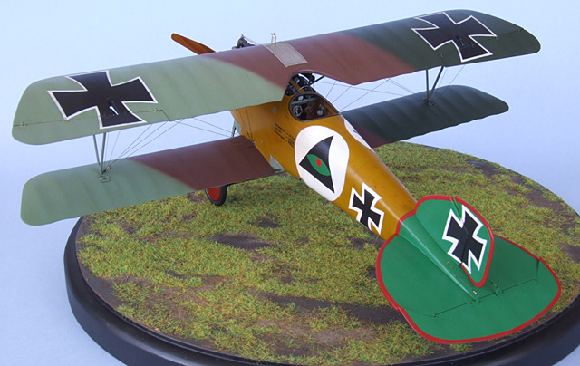
Hans Berr – Jasta 5 April 1917 |

Roden's 1/32 scale Albatros D.III is available online from Squadron.com
Roden (No. 606) Albatros D.III 1/32 scale
My first venture into the netherworld of biplanes began a couple of years ago with the 32nd scale Battle Axe Fokker D.VII. I should have heeded the warning on the box for this one… it was an absolute battle of a kit and I ended up taking an axe to it. It certainly put me off biplanes for a while. Recently, after seeing a friend’s build of the Roden Fokker Dr.1, I decided to give the Roden kits a go.
I started out with the intention of building Rudolf Berthold’s D.III of Jasta 14 with the winged sword painted on the side. I really wanted to have a crack at the woodgrain effect as well as a clear-doped fabric tail sporting the Albatros logo. As always the madness that has become my experience of modelling had other plans.
Aftermarket Products Used
I spent a fair while reading reviews and builds of various biplane kits on the Internet. There were numerous methods of creating the woodgrain effect, rigging etc but in general I was trying to get my head around the build procedure so that construction would go smoothly without any tricky situations arising. It became obvious that a fair amount of forethought at each stage of construction was needed.
I will now dispense my experience with this kit step-by-step.
PROPELLER ADVENTURES
First the propeller was primed then painted Tamiya XF60 Dark Yellow. I allowed it to dry for a couple of hours while I made up some masks cut from Tamiya tape to show the laminations (2-3 laminations per blade is enough) – a curved one for the front and a straighter one for the back. I stuck the mask on at an appropriate place and sprayed along its edge with Tamiya XF64 Red Brown. The mask was then pulled up and repositioned for the next lamination. Then I damp brushed a grain effect down the length of the blades with a 50/50 mix of Windsor and Newton raw umber and burnt sienna oil paint and lastly sprayed the whole with numerous coats of a 50/50 mix of Tamiya X26 Clear Orange and X24 Clear Yellow.
At least this is how it should have happened. What really transpired was this…
The propeller was painted as above but with 5 laminations then I pre painted the spinner and its base plate and glued them all together. The propeller hub was shored up by gluing it to the spinner base solidly with some thick plastic card on its sides (you don’t see it once the spinner is attached). Later one side of the spinner came unglued so I lightly touched in some Tamiya Extra Thin Cement. Due to some idiot scientist inventing capillary action it proceeded to create a massive thumbprint in the spinners paintwork. Yay, more unnecessary sanding and painting. But that’s not all! I then decided I couldn’t live with a prop with too many laminations so I masked everything up again and repeated the whole process. This time it looked much better. As I sprayed a gloss varnish layer to protect my work of art a blue chunk of paint materialized and stuck into it. I removed it with tweezers which also took the paint right back to the plastic - GAD! I left it to dry overnight and patched up the hole with a fine paintbrush and then resprayed with the clear orange/yellow mix. Unfortunately the varnish hadn’t completely dried so as the orange/yellow dried it cracked up like a muddy lakebed in a drought – SIGH! I left it to dry for a couple of days while I thought of ways to avoid another repaint. The answer came by brushing on several coats of Future to fill all the cracks and the prop was finally perfect. After the Future coat was dry I put on the Roden prop decals which promptly silvered and fell off – NOT A GOOD START!
INTERIOR
I started out by making all the interior subassemblies so that I could dry-fit them and check for any potential problems. I added locating tabs to the inside of the fuselage in inconspicuous places to aid in its alignment.
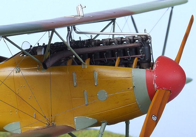
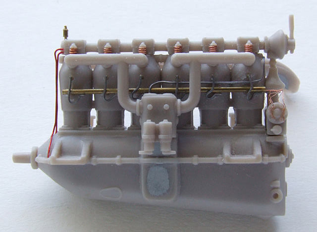
ENGINE (Roden Step 1,3,5,6)
Glue both engine halves together first and sand the seams. Make sure you insert part 9Z if you want to attach the propeller. I replaced kit part 6Z with brass tube, as this looks more realistic. Chop the bottom half off part 3Z as this hinders engine insertion and you never see it anyway. Glue together parts 1Z and 5Z but don’t attach them to the engine until after you have painted it. Leave out part 7B as the instructions have it in the wrong place – attach it to the wing radiator in the final stages of the build.
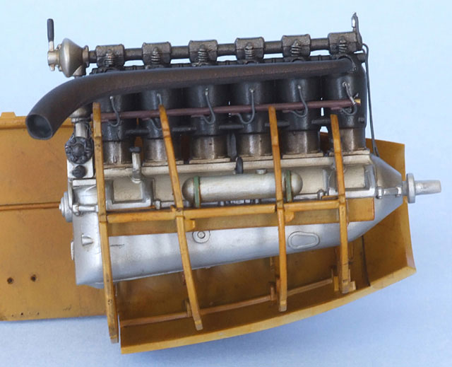
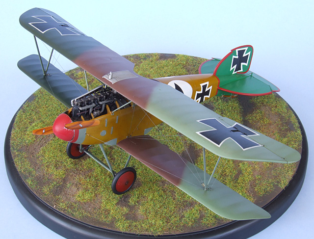
Next I detailed the engine using Mark Miller’s wonderful structural illustrations of the Albatros D.V at www.wwi-models.org. Once complete I airbrushed the whole thing using various mixtures of Mr Color lacquer paints (8 Silver – 28 Steel – 2 Black). I then picked out the wiring etc with a fine paintbrush and finished up with several dirty washes using oil paints. I dremelled a hole in the end of the exhaust pipe and added brass wire to its attachment with the engine so that it would glue on strongly later.
ENGINE MOUNTING STRUCTURE (Roden Step 4,9)
Don’t attach part 25A to part 9A now, wait until after you permanently glue the engine to the mounting structure as it gets in the way of engine insertion. Now listen closely – part 45A slopes rearwards at an angle at the top. To line it up use the tiny attachment lugs on the interior of the fuselage as a guide. Also note that the sharp pointy top bit goes to the starboard side (this part’s lugs are on the wrong side in the Roden drawing.)
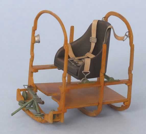
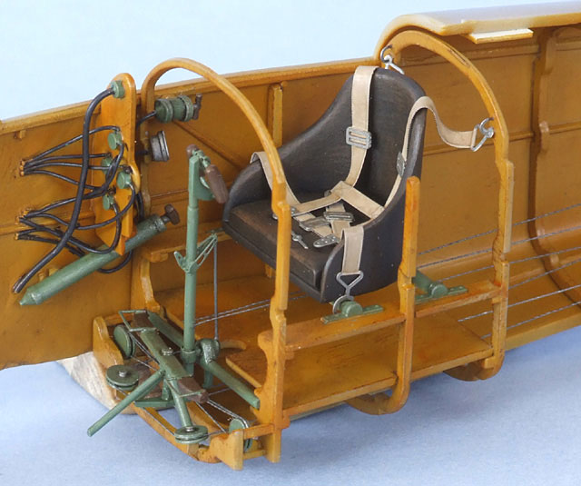
COCKPIT STRUCTURE (Roden Step 7,8,11,12,13)
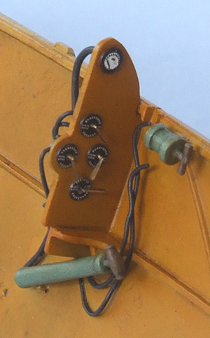
In step 7 keep the flying controls as a separate assembly until later. In steps 12,13 leave the seat off until after painting – much easier this way. I attached the rudder control assembly (Roden Step 8) to the lower front end with plastic card, as it is the only way to be able to attach the control cables later on. I then scratchbuilt various pulleys and added them to this structure to simulate the control cable set-up.

Unfortunately there are no decent references available on the D.III and Roden’s offering is incomplete and not a workable mechanism. All the “metal” cockpit parts were painted Humbrol H78 UK Cockpit Green, PE added where necessary and wiring going to the various instruments.
FUEL TANK STRUCTURE (Roden Step 16)
I prepainted all parts and weathered them. The main thing to watch here is that part 5A must slope forward to touch part 37A along its upper edge or the ammo chutes will not meet up with the machine guns later on. Of course I found this out the hard way.
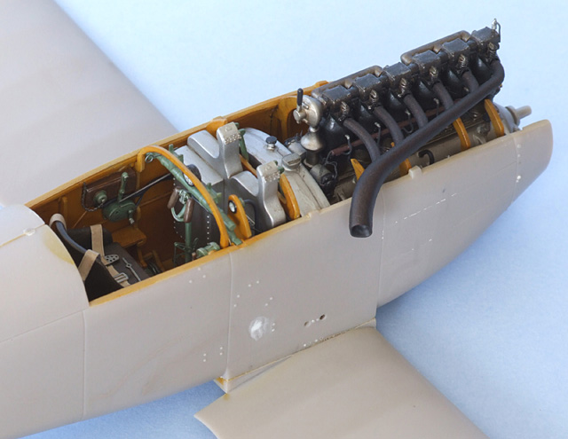
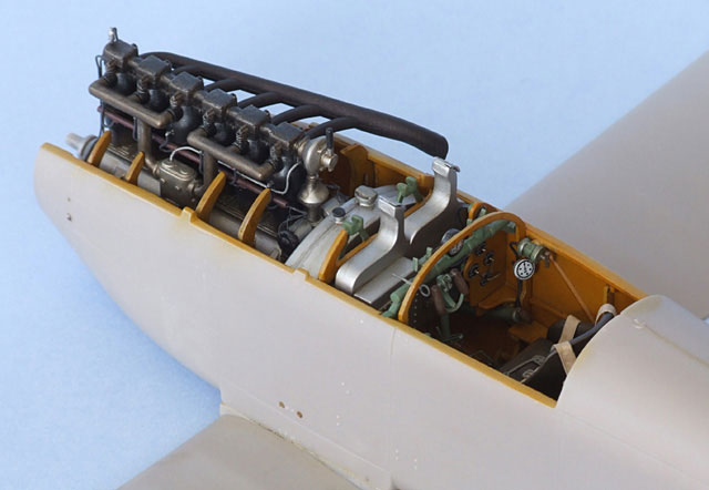
FITTING IT ALL IN
The dry-fitting of the engine structure proved confusing and revealed that it didn’t fit very well at all; the tiny alignment lugs were next to useless. For correct positioning the rearmost part 38A should sit just aft of the lower wing opening. My starboard fuselage half was slightly twisted and the cowling (part 5B) was squashed flat and too short by almost 1mm. It’s a very 3-dimensional mess! It took me a while to figure out just where the engine structure should be positioned (you won’t find any help in the instructions).
Eventually I glued it to the port side (with engine tacked in place and prop/spinner attached) and the other sides with taped together to aid in alignment while the glue dried. Extra strips of plastic were added between the front of the structure and the fuselage side to make sure the front end stayed round. On the real aircraft the front of the fuselage is slightly wider than the spinner base plate so you’ll have to drill a bigger hole (4mm) in the plate to allow it to fit over the wide part of 9Z so that the whole prop/spinner sits further aft.
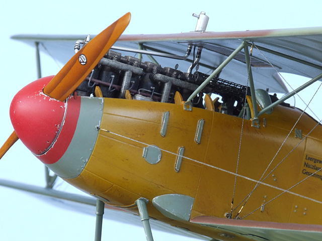
To fix the cowling problem I decided it was easier just to cut where it would actually detach and leave the front end open so you can see all the engine detail. After all this rigmarole the engine ended up being slightly twisted to port.
Next I painted the Cockpit structure, engine structure and fuselage interior Tamiya XF57 Buff. I followed this with a damp-brushing (1/2 way between normal brush painting and dry-brushing) using a coarse brush and a 50/50 mix of raw umber and burnt sienna oil paint to render a streaky effect. Then I sprayed over it with several coats of Tamiya X24 Clear Yellow. Once this was dry I gave it a coat of gloss varnish and then a wash with the same oil paint mix, finishing off with a coat of satin varnish.
The cockpit structure was glued to the starboard fuselage side and I attached the seat (painted with a mix of Tamiya XF64 Red Brown and XF1 Black) to which was added the Eduard PE seatbelts. Then I attached the control stick assembly (remember to offset the controls if you have repositioned your ailerons, elevator or rudder). I also glued a thick strip of plastic at the rear of the fuselage to which I would attach the control cables. For the cables (and all my rigging) I used woven nylon cord superglued in position and painted with Tamiya XF56 Metallic Grey.
The Fuel tank structure was then glued in place just ahead of the cockpit – no real problems there.
Lastly, before the fuselage joining I had to think how the rigging would work and make sure that I had pre-drilled holes in all the right places. It’s best to leave out part 26A until later or you will probably break it.
FUSELAGE
Once the halves were together the joins were filled and sanded smooth. You will notice two holes on the fuselage sides just above where the lower wing joins – they are bracing wire holes. You will need to remove these as they are in the wrong position (drop them straight down to the bottom edge). All the other inspection panels etc were removed to make way for their Eduard PE replacements. I also reached inside and ran superglue into the interior structure joins with the fuselage sides to shore it all up.
WINGS
The lower wings were attached next with little fuss, after minor trimming. As an aside, the surfaces of all parts needed to be sanded smoother as they had a pebbled effect on them – way overdone if it is supposed to represent fabric. Time consuming, but in my opinion necessary. I decided that it would be easiest for all the rigging wires to exit through the top of the upper wing so I then drilled the appropriate holes using a 0.44mm bit.
CONSTRUCTION CONTINUES
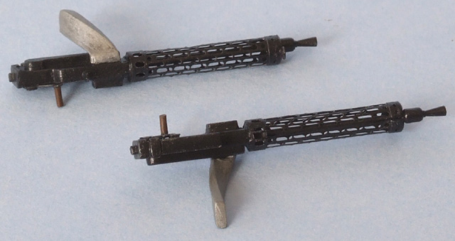
Once the fuselage sanding was complete I attached part 26A. Next to go on are the machine guns which I upgraded using the Eduard PE. You will quite probably have alignment issues with the petrol tank structure MG attachment points and need to file a few bits to make sure the MGs point in the right direction. Part 24A is far too short to reach the ammo bin (you won’t really notice it) and it conflicts with its shroud on the cowl (part 5B) so you will have to correct this issue with your trusty Dremel. Note: Eduard would have you glue dirty great big handles to the MG cocking levers as shown in my photo – I have never seen this on any Spandau (a small knob at most) so I cut them off.
Once the MGs were on I could finally attach the cockpit top. This needed a bit of shimming and much strenuous bending to fit properly; it’s still a bit warped. Leave the exhausts and windshield off until the end of construction. Once its joins were sanded and panel lines rescribed I glued on the tail bits, which fit perfectly. I used the kit control horns (parts 11D) as the Eduard PE is far too skinny. Lastly I attached the lower wing fillets and after a bit more bogging and rescribing it was ready to paint. Before painting I finished up the rest of the subassemblies.
UNDERCARRIAGE & WHEELS (Roden Step 15)
The undercarriage went together without too much difficulty although it is pretty flimsy. I inserted brass wire so that it would attach the fuselage with some strength. I also replaced part 4B with brass tube to make it stronger. Lastly I wound fine lead wire around the axle to simulate the rubber band shock absorbers on the real aircraft.
Since the wheels are best left off until later I had to glue parts 9D permanently to 6D – the wheels won’t spin but then again it’s not a toy you know.
These assemblies were all dry-fitted to ensure a good fit and then painted and set aside for later.
WING TRIAL FIT
Now it was time to do a trial fit of the top wing to see what nightmares lay in wait. I tacked the struts to the upper wing with white glue and lowered it gingerly into position. To my surprise the fit and alignment was near perfect – I love it when a plane comes together!
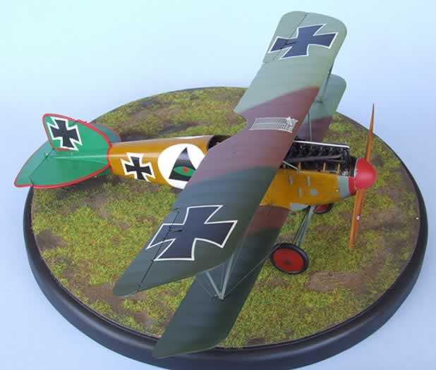
The whole model was initially primed with Humbrol H1 Primer. I painted both sides of the upper and lower wings first then post-shaded using that particular colour lightened slightly with white. I then masked off the lowers to paint the fuselage woodgrain. The woodgrain I used for the fuselage follows the same method I used for the interior although for the base coat I used a 50/50 mix of Tamiya XF57 Buff and XF60 Dark Yellow with patches of straight buff. I used post-it notes to mask off several panels so that I could change the direction of the damp-brushing. Note: if you are too subtle with your woodgrain effect the end result will look more like cardboard than wood.
Paints used are as follows (all enamels):
Topsides:
Dark Olive Green: 5 – Tamiya XF58 Olive Green / 2 – Humbrol H115 US Dark Green FS 34079
Venetian Red: 6 – Humbrol H160 German Red-Brown / 1 – Tamiya XF2 Flat White
Pale Whitish Green: 1 – Humbrol H105 Marine Green FS 340971 / 2 – Tamiya XF2 Flat White
Undersides:
Sky Blue: 3 – Tamiya XF23 Light Blue / 1 – Tamiya XF21 Sky
Cowling / Struts etc:
Pale Greenish Grey: 1 – Tamiya XF65 Field Grey / 4 – Tamiya XF2 Flat White
MASKING ADVENTURES
Due to the atrocious sticking ability of Roden’s decals I decided to avoid them completely. In my travels I came across Spada Decals but I didn’t like many of their schemes and you have to cut out the decals so I decided to mask and paint everything. I now had to find another scheme where I could meet my new requirements –
- woodgrain fuselage
- 3-colour camouflage
- not a white tail
- no tail code numbers
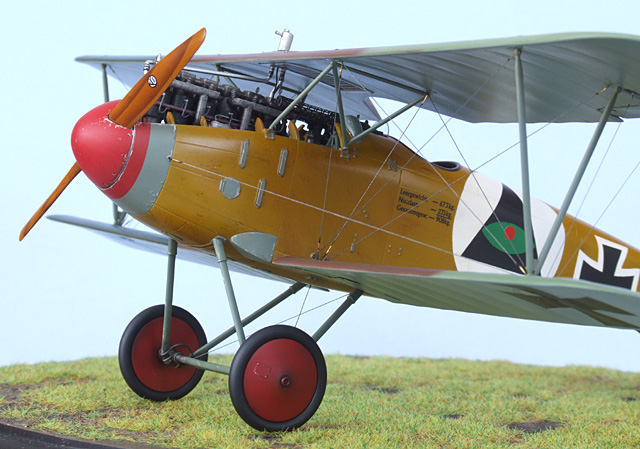
Therefore I only needed the factory data block stencils below the cockpit and the prop logo - these I gleaned from the Aeromaster (AN32022) Albatros D.I – D.III Woodgrain pattern decal set. In this set there are numerous other decals such as factory-applied serial numbers that go on the main struts – but where? Aeromaster says consult your references, which are practically non-existent – thanks for nothing Aeromaster. These decals are a bit thick and I honestly think it is far easier and faster painting the woodgrain than using decals. Now that I had the essential decal components I settled on the Spada scheme of Hans Berr – Head honcho of Jasta 5, April 1917 and recipient of the Blue Max medal.
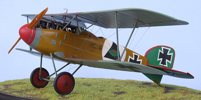
I used the Roden decals as templates to cut out masks for the Eisernkreuz (14 in all) and then used my technical drawing skills to create the Eye of Providence (all seeing eye in a triangle) for the fuselage side. This marking is a well-known Stonemasons symbol and Hans Berr may have been one as he also designed and built hangars for Jasta 5 (although I couldn’t find any corroborating evidence for my theory).
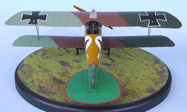
The triangle and fuselage crosses were the only really problematic masks although they were all tricky to line up properly. I used 40mm wide Tamiya Tape for most of them. A problem with Tamiya tape, particularly the wide stuff, is that it leaves behind residue on the enamel paintwork particularly if it hasn’t dried for long enough. Usually though a varnish coat will make this all disappear; but not the Estapol varnish I usually use which turns these patches brown. I also learned that wet gloss paint will seep under the masking tape when its applied over a matt surface necessitating numerous resprays particularly with white – there are some thick layers of paint on this puppy! For the eye I used my own interpretation of the colours based on a B&W photo of this aircraft; it also seems possible that it actually had the OAW rounded rudder. The Tail was masked by first tracing the outline of the tail onto paper then cutting tape to fit – easier than I had envisaged. The green used is Humbrol H2 Gloss Emerald Green, which in afterthought I should have lightened up some more. The edges were sprayed Tamiya XF7 Red lightened with white, as straight red would have turned very dark over the green base colour.
I was actually glossing the area below the cockpit to apply the factory data block decal and the Estapol overspray turned parts of the white circle brown where the masking tape had been. I then thought to use the Humbrol Glosscote but thought it might also do the same thing. The only other products I had to use were Future or Microscale gloss acrylic varnish. The Microscale instructions on the side of the bottle said to thin with alcohol or water so I put a couple of drops in my airbrush paint cup and added the same amount of isopropyl alcohol. The result was a thick whitish soup. Must need more iso… just more soup. Hmmm… lots more iso… a paint cup full of soup. I wonder if I can spray that?… nope airbrush is all gummed up. Ages pass as I clean out the airbrush. Lets try it with water… Ah that’s better. Now lets spray it… side of fuselage is covered with beads of varnish as enamel surface repels it… airbrush gums up again. I wipe off Microscale’s feeble goo and get busy cleaning my airbrush. As I’m cleaning it the needle and spring (Aztec tip) pings away into the next dimension. Much profanity ensues and the neighbours kid gets an early education. In the end Future won the day - and later on the Humbrol varnish also proved its worth.
WEATHERING
After a coat of Humbrol satin varnish the model was given an overall wash with a 50/50 mix of Windsor & Newton Artisan water mixable raw umber and burnt sienna oil paint mixed in Bars Bugs car window washer detergent. Oil stains were then made by further darkening the original wash with black. Some restrained chipping using Tamiya XF16 Flat Aluminium was also applied to the metal parts with a fine brush.
FINAL ASSEMBLY
Firstly the pre-painted rigging wires were glued securely to the lower wing and fuselage side. Then the struts were tacked to the upper wing with superglue along with the rear radiator pipe (part 7B). This assembly was then lowered into position. It is quite a fiddly procedure and is a good example of how human evolvement has not kept pace with the obvious necessity to have a third arm. The radiator pipe kept getting in the way so I cut a bit off the bottom of it (yes you can see that it doesn’t connect to the engine – bugger). Once attached, I fixed the joints with superglue and found the whole unit to be surprisingly strong.
RIGGING
I fed all the “wires” up through the holes I had pre-drilled in the upper wing. Now I pulled each wire tight and put a drop of superglue in each hole. Glue the corresponding wire on each wing so that you don’t induce any twisting. Make sure your model is sitting upright on a flat surface too! If you turn it upside down or sideways the weight of the top wing will cause the wires to sag – you want it all to look sweet when it’s standing on its feet. As it happens the particular nylon I have used sags when temperatures get below about 15 degrees Celsius. Once all the wires are tight cut off the nylon in the hole with a sharp pointed blade and progressively fill to the top with superglue. Once this had cured I painted on a bit of Mr Surfacer 1200 and sanded it smooth; this left only tiny patches to respray, which was easily masked with post-it notes. I then varnished with the whole top surface, weathered it and sprayed a final coat of satin varnish to finish. For the control cables on the wings I used stretched sprue as it was easier to attach. Next I touched up the wires where paint had come off and then simulated the turnbuckles with white glue painted black and the middle section done in Tamiya X12 Gold Leaf.
UNDERCARRIAGE
The undercarriage went on without a hitch although it proved to be very wobbly (the model is quite heavy). The rigging wires helped a bit but not a great deal. I slapped the wheels on and found that the model sits a bit left wing down – once on the diorama base no one will notice.
Finally the last fiddly bits can go on, exhaust pipe, front radiator pipe, tailskid, part 21A for want of a better term, windshield and lastly the prop glued in place permanently – Permission to make aeroplane noises Sir!
Biplanes are groovy baby!
This could be considered an awesome kit and the fit of the parts is near perfect although it is let down by a few things - these in the main being the diabolical engineering drama in the front fuselage, rubbish decals and dodgy instructions.
This being my first biplane I learned many lessons and was surprised at how easy they are to build – not nearly as foreboding I one might think. The finished model certainly does draw your attention, as there is plenty to look at. I think I feel an addiction starting…
Model, Images and
Text Copyright © 2009 by Bruce Salmon
Page Created 7 January, 2009
Last Updated
7 January, 2009
Back to HyperScale
Main Page |
 Home
| What's New |
Features |
Gallery |
Reviews |
Reference |
Forum |
Search
Home
| What's New |
Features |
Gallery |
Reviews |
Reference |
Forum |
Search