|
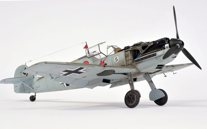
Eduard's 1/32 scale
Messerschmitt Bf 109 E-1
by Brett Green
|
Messerschmitt Bf 109 E-1 |

Eduard's 1/32 scale Messerschmitt Bf 109 E-1 is available online from Squadron.com
Background
The Messerschmitt Bf 109 A, B, C and D were powered by the Junkers Jumo engine. The Spanish Civil War presented the opportunity to test these revolutionary fighters in action, and they proved their worth in combat with Legion Condor over the skies of Spain.
The Messerschmitt Bf 109 E series was the first of the family to be fitted with the Daimler Benz DB601A engine, resulting in a significant improvement in performance.
Two variants were manufactured in parallel - the lightweight Bf 109 E-1 which retained the wing-mounted 7.9mm machine guns of the earlier Bf 109 B, C and D; and the Bf 109 E-3 which was fitted with one 20mm MG FF cannon in each wing. Both variants featured two additional 7.92mm machine guns in the cowl.
1,183 Bf 109 E-1s were delivered. They saw first saw service with Legion Condor in Spain, then continued in widespread action alongside the Messerschmitt Bf 109 E-3 in Poland, the Low Countries, across the English Channel in the Battle of Britain and in the Balkans.
But do we really need another Bf 109 E?
The Messerschmitt Bf 109 G and K have been well represented in plastic over the last few years. Hasegawa has just about cornered the market with excellent kits of these mid and late war variants in both 1/48 and 1/32 scale. The Hasegawa 1/48 scale Bf 109 F is also quite respectable.
In 1/48 scale, the early Bf 109s have done quite well too. Both Hasegawa and Tamiya offer Bf 109 E-3 and E-4/7/Trop kits. Hasegawa even released a couple of Bf 109 E-1 kits in 1/48 scale, but these were really their E-3 plastic with resin plugs for the cannon bulges in the wings and a set of DIY instructions to recreate the machine gun wing of the E-1.
The situation in 1/32 scale has not been so rosy. The two major options are typical products of the 1970s. Hasegawa's 1/32 scale Bf 109 E-3/4 has raised panel lines, questionable shapes, peculiar (but fashionable for the day) cross-hatched fabric surfaces and ficticious cockpit and wheel wells.
The Matchbox kit was visited by the Mad Trencher, with wide, soft panel lines, chunky detail, gimmicky working parts and a poorly shaped nose.
And, of course, nobody had ever offered a Bf 109 E-1 in this scale.
Until now.
Eduard’s 1/32 scale Bf 109 E-1 in the box
Eduard’s brand new 1/32 scale Messerschmitt Bf 109 E-1 comprises 169 parts in olive coloured plastic, five parts in clear, two photo-etched frets (one in colour), canopy mask, markings for four aircraft plus full stencil data.
The parts are very well moulded and surface detail is state-of-the-art. Finely recessed panel lines are supplemented with even finer rows of rivets.
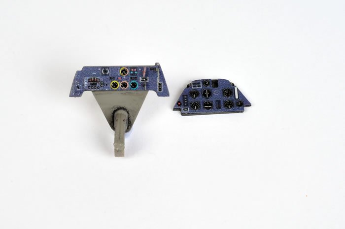
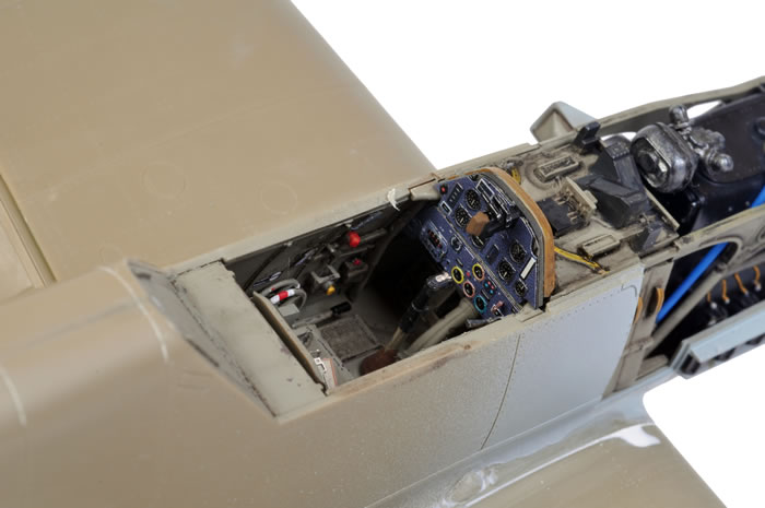
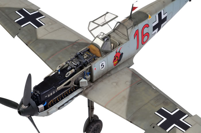
Detail is excellent. The plastic cockpit parts are combined with colour and nickel-plated photo-etch to deliver an authentic front office. Colour photo-etched parts include the instrument panel sandwich, fuse panel and harness straps.
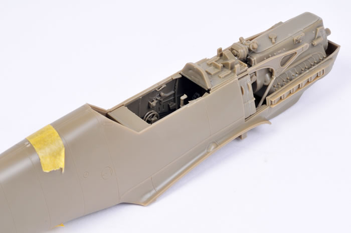
A full engine is supplied, but this is an optional element. Eduard has taken notice of customer comments about the complexity of some of its earlier kits including the 1/48 scale Fw 190 and Bf 110 families. In the case of this 1/32 scale Bf 109 E-1, the DB601A engine may be installed and displayed, or the cowl may be glued closed without the engine. Alternate parts are supplied to mount the propeller, the exhaust stubs and the cowl guns if the second option is chosen.
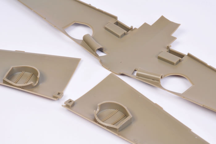
All control surfaces are separate - the flaps, leading edge slats, ailerons, elevators and rudder. The rudder actuator is provided in photo-etched metal. Flaps are moulded with tabs that will pose them dropped without modification, but it will be very easy to slice off the tabs and reposition if desired.
The oil cooler and wing radiator front and rear faces are all supplied as photo-etched grilles.
The main wheel wells are nice done. The ceiling of the well features a ring of raised rivets and reinforcement strips. The sides of the main wells are boxed in with separate parts.
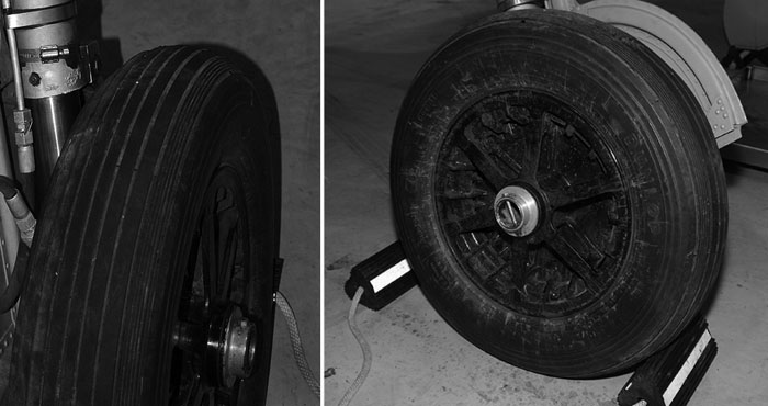
At first I thought that the main wheels were too narrow, but comparing with reference photos I think the width is about right. However, the detail inside the wheel hubs is oversimplified and too shallow. I have included a few photos of a Bf 109 E wheel below for an idea of what the real thing should look like.
The early style canopy with the low horizontal framing is provided as three separate parts. External armoured glass for the windscreen is also included. Although it is not used on any of the kit's marking options, this was sometimes retrofitted to Bf 109 E-1 abd E-3s. The final clear part is the gun sight.
Decals have been printed by Cartograf. Register is perfect, colours are rich and opaque, and visible carrier film is non-existent. They don't come much better than these. I particularly like the interpretation of RLM 04 Yellow on this sheet too.
Accuracy
The overall shape and most of the details conform to published dimensions, respected plans and wartime photos.
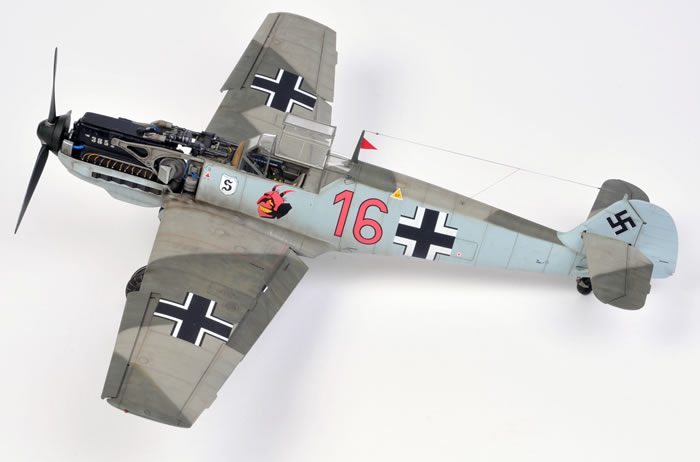
Apart from the shallow wheel hubs, the only other shape issue is a slightly odd contour behind the cockpit. The shape and curves of the rear fuselage look perfect in profile (i.e., from the side) and in plan (from the top), but when viewed from a high, three-quarter angle, the line of the fuselage extends straight back from the canopy over the length of one full panel – around 2 cm – before curving to the rear of the aircraft. This creates the illusion of a bulge when viewed from this high side three-quarter angle, whereas the fuselage should feature a smooth curve from the rear of the canopy back to the empennage.
This is by no means a major issue. In fact I was only conscious of the shape after I painted the high camouflage demarcation line, which coincides with the area in question. The “bulge” is small enough that it could be sanded down, but most modellers probably would not bother.
Before you start building the model, you will need to decide whether you want to display the engine or if you want to fit the cowling. The cowl will not fit over the completed engine.
The quandry facing Eduard would have been that if they designed the cowl to fit over the engine, then the engine would have to be noticeably underscale due to the necessary thickness of the plastic of the engine cowl. It is not a particular problem though, as Eduard offers alternate parts to mount the exhausts, propeller and machine guns if you want to omit the engine and close the cowl.
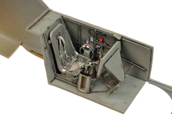
Eduard supplies all the parts required for a beautifully detailed cockpit, however the perforated holder for the oxygen bottle is too tall. The bottom two rows of holes should be cut off to obtain a more correct height.
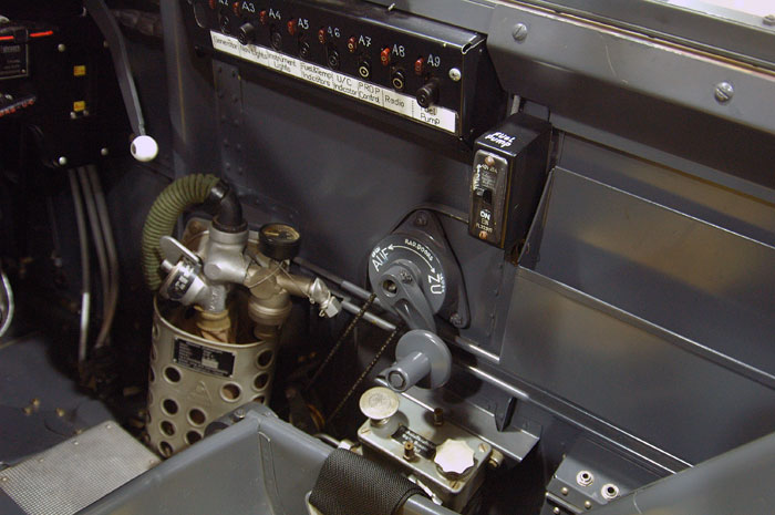
Unfortunately, I saw this comment by Frank Crenshaw on the Plane Talking Forum too late for my cockpit. The reference image above shows the relative postion of the oxygen bottle to the other items on the starboard sidewall.
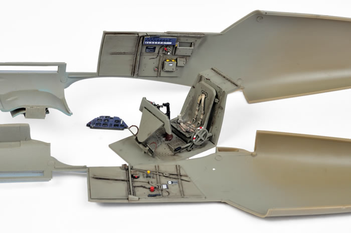
The plastic and uncoloured photo-etched parts for the sidewalls and cockpit tub were glued together. Don’t forget to grind off the raised detail from the switch panel on the upper starboard sidewall.
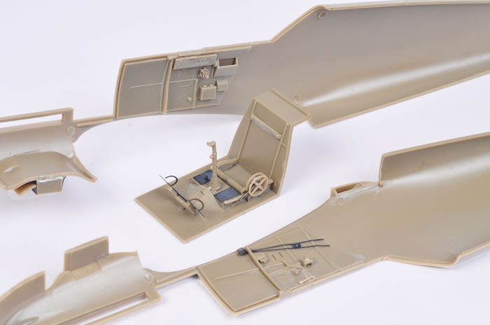
The basic engine and firewall parts were also assembled at this stage.
Before proceeding with painting the interior elements, I test-fitted the cockpit and engine assemblies between the fuselage halves.
The fit was very encouraging except for a minor issue with the oil cooler housing. More on that later.
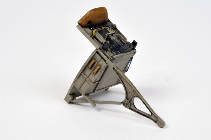
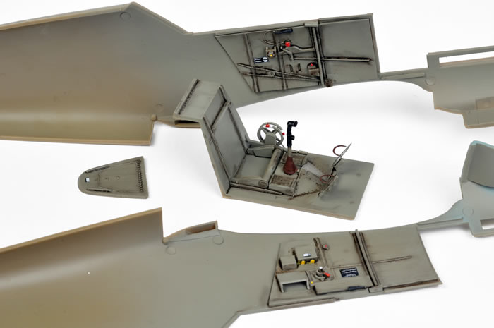
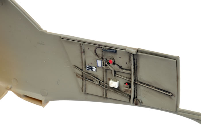
The cockpit was painted according to my usual practice. Before the colour photo-etched parts were added, the cockpit sub-assemblies received a coat of Gunze H70 RLM 02 Grey followed by a thin wash. This was a 50/50 mix of Lamp Black and Raw Umber oil paint heavily thinned with Mineral Turpentine. On a warm day I can place the washed parts in the sun and they will dry in around an hour, but we were experiencing some unseasonably cool weather so I had to wait a seemingly interminable 24 hours before the cockpit parts were ready for the next stage.
Smaller details were picked out with a small brush using a combination of Tamiya and Vallejo white, red, yellow and blue paints. The boot of the control column was painted brown.
The only additions that I made to the cockpit were a couple of Waldron cockpit markings and a placard decal from MDC’s excellent 1/32 scale Luftwaffe Instruments decal sheet.
Now the colour photo-etched parts were added to the cockpit. These were mainly secured with Gator Glue. This acrylic adhesive is strong when set but permits the parts to be adjusted while the glue is drying. The harness straps were attached using super glue. The colour photo-etched really lifted the standard of the cockpit with their fabulous detail and authenticity.
The harness straps were weathered with a thin wash as I thought that they looked a little stark straight off the fret.
I also added some “micro-chipping” to edges and larger surfaces with a brown waterproof marker.
After I posted a few photos of the model to HyperScale’s Plane Talking discussion forum, an eagle-eyed visitor pointed out that I had glued Part F3 into the wrong position on the port cockpit sidewall (thanks Goran). I had transposed the positions of this part and photo-etched part PE9.
I had not trapped them between the fuselage halves at this stage, so I prised the offending part off the sidewall. Unfortunately, in the process, the small part was launched into the distance never to be seen again. I rebuilt the part using three narrow strips of plastic, and two concentric circles formed with my Waldron Punch and Die set. Photo-etched part PE9 was more successfully relocated to its correct position.
I was pleased that I had gone to the trouble of correcting this error.
The cockpit was now ready for installation, but there was still some more work to be done before the fuselage halves could be joined.

The width / fit of the oil cooler housing ceiling (part A12) needed to be addressed before the oil cooler assembly is trapped between the nose halves. Unmodified, this is too wide and interferes with the fit of the fuselage. I trimmed the sides of the chin oil cooler to improve the fit.
I also had to cut down the height of the oil cooler mesh to get it to fit.
After I had finished assembling the oil cooler, I read another comment on HyperScale’s Plane Talking forum about an errata photo-etched fret being included to correct the tall oil cooler mesh. I thought that I had thoroughly examined the contents after I pulled both of the standard frets out of the re-sealable bag and did not see any extra parts. Even so, I thought I had nothing to lose by pulling the cardboard out of the little bag too.
Lo and behold, in between the two cardboard sheets (I thought it was a single piece) was the errata fret with the shorter mesh grilles for the front and back of the oil cooler!
It was too late for me to use the parts but make sure you dig into the plastic bag and use yours.
It is also important to note that that the recessed lip at the back of the oil cooler housing ceiling needs to protrude slightly back into the bottom fuselage cavity. This lip is a locating aid for the front of the bottom wing section. I got this wrong too.
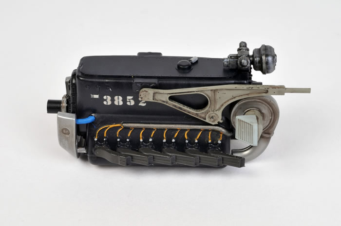
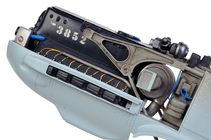
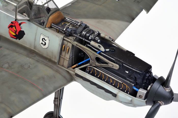
Building and painting the engine is easy enough, but I gave some extra thought to the final sequence of assembly. After the separate components were painted, I glued the starboard side engine mount to the rear engine bulkhead (Part G2), and secured the port side engine mount (Part G4) to the engine. I did not glue the lower port side engine support strut (Part G31) at this stage. These parts were then put aside until thoroughly set.
If you are planning to display the engine, it is important to note that the exhausts on the assembled engine will not fit through the slots in the side of the nose after the horseshoe coolant reservoir (part G25) has been glued to the front of the engine. This is easily addressed though. When you are assembling the engine, do not glue the last exhaust stack in place (I had to break mine off as I had already glued them. You can see the scarred plastic in some of the photos). This leaves enough leeway for the exhausts to be pushed through the slots, and the last stack on each side can be fitted from the outside after the fuselage halves have been joined.
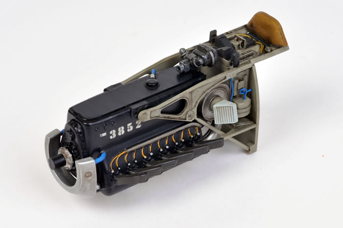
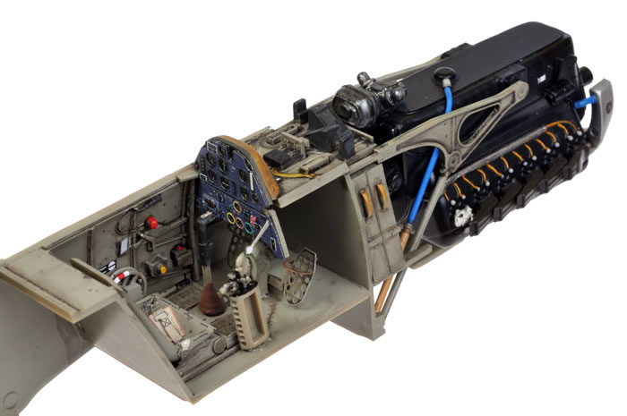
The engine was painted using Tamiya X-18 Semi-Gloss Black for the block, Tamiya AS-12 Airframe Silver for the horseshoe coolant reservoir, Vallejo’s “Oily Steel” for the interrupter gear, Alclad Magnesium for the supercharger and Gunze H70 RLM 02 for the rear bulkhead and engine mounts. The moulded-on ignition harness was painted silver and dark yellow. Smaller details such as straps and electrical wiring were picked out in tan, yellow and blue Vallejo acrylics. The level of detail in the is good straight from the box, so I only added two small wires on the rear port side.
The canvas boot covering the rear of the instrument panel was painted in several shades of tan.
I applied stencil number decals from MDC’s 1/32 scale DB 605 engine set to add some more interest in this area. A thin oil wash was also applied to bring out the detail.
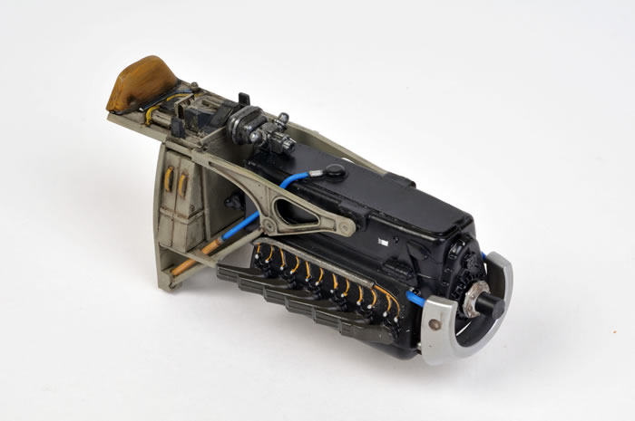
All the engine elements were assembled and the cockpit floor/bulkhead was attached to the port side of the fuselage interior. The engine assembly also glued to the port fuselage half. The exhausts slipped easily through the slot with the last stack removed.
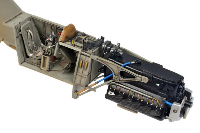
The starboard fuselage half trapped the engine and cockpit parts with no complications or gaps.
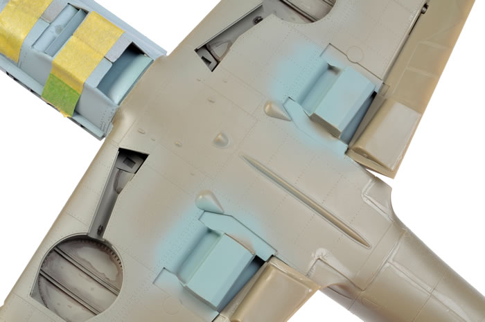
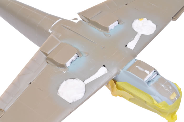
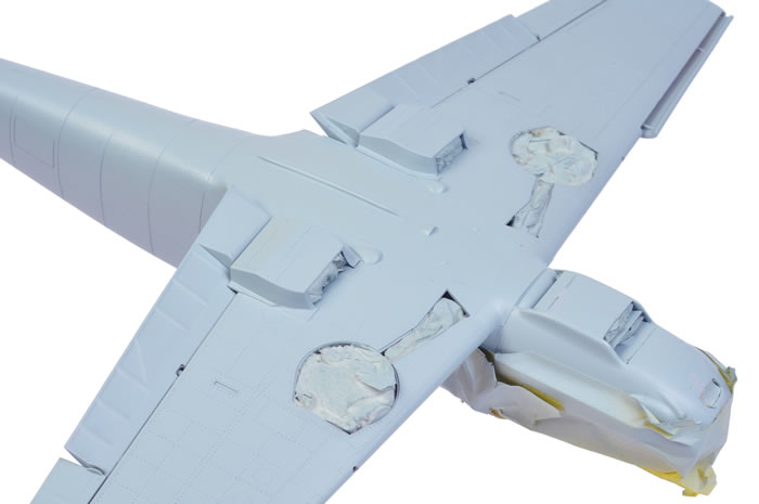
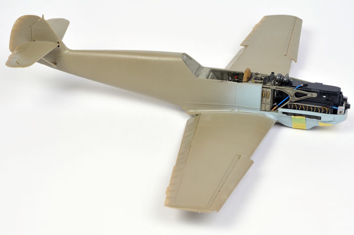
The wheel wells and wings were assembled per instructions. When set, the wings were offered to the fuselage. The fit was tight, especially at the front and rear lower joins, but a tight fit was eventually obtained after a few minutes fiddling. The dihedral looked pretty good but I took out insurance in the form of Tamiya tape stretched from wing tip to wing tip.
Horizontal tailplanes and the rest of the control surfaces were added next, including the flaps and leading edge slats in dropped positions. In fact, the tabs on the flaps are designed to secure these parts in a partly dropped pose.
Only minimal filler was required on the shallow sink marks on the upper wings, and around to cover a small step at the join between the trailing edge of the wing and the bottom of the fuselage. I rescribed the lengthwise panel lines on the bottom of the fuselage and the spine, as the join was too good to suggest these panels!
The main airframe was now looking very much like a Bf 109 E.
Overall, fit is very good but you do need to make sure that parts are aligned properly before applying adhesive. Any imprecision might come back and bite you.
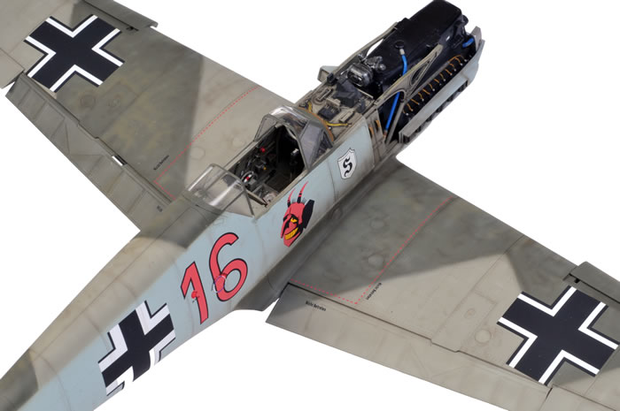
Painting
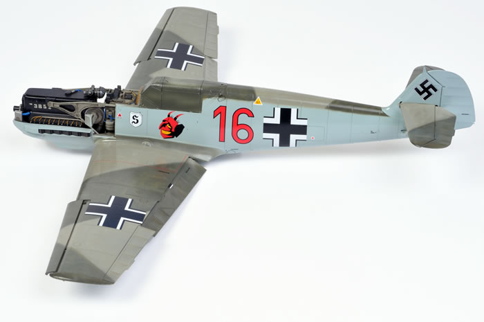
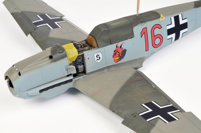
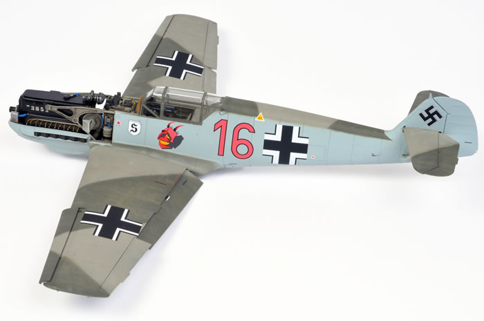
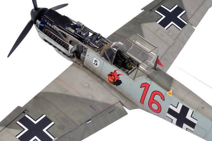
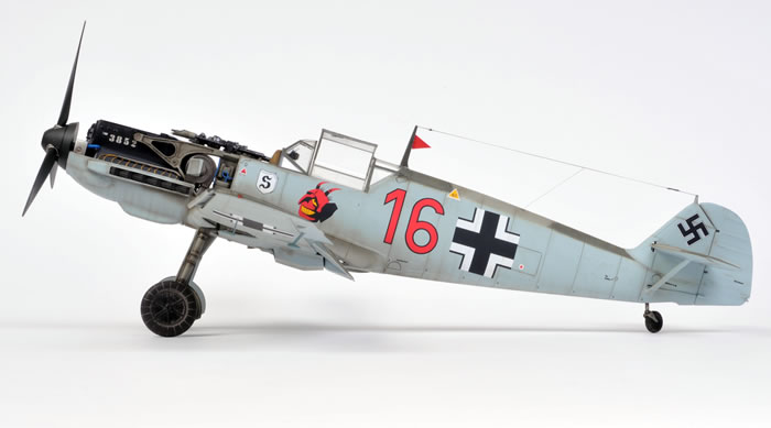
 Although Eduard offers a great selection of interesting markings, and their decals appear to be some of their best yet, I could not resist the fabulous devil’s head emblem on “Red 16” of 2./JG 27. This was one of the options on EagleCals’ decal set number EC#121 – one of three brand new decal sheets designed especially for Eduard’s 1/32 scale Bf 109 E. Although Eduard offers a great selection of interesting markings, and their decals appear to be some of their best yet, I could not resist the fabulous devil’s head emblem on “Red 16” of 2./JG 27. This was one of the options on EagleCals’ decal set number EC#121 – one of three brand new decal sheets designed especially for Eduard’s 1/32 scale Bf 109 E.
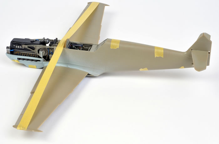
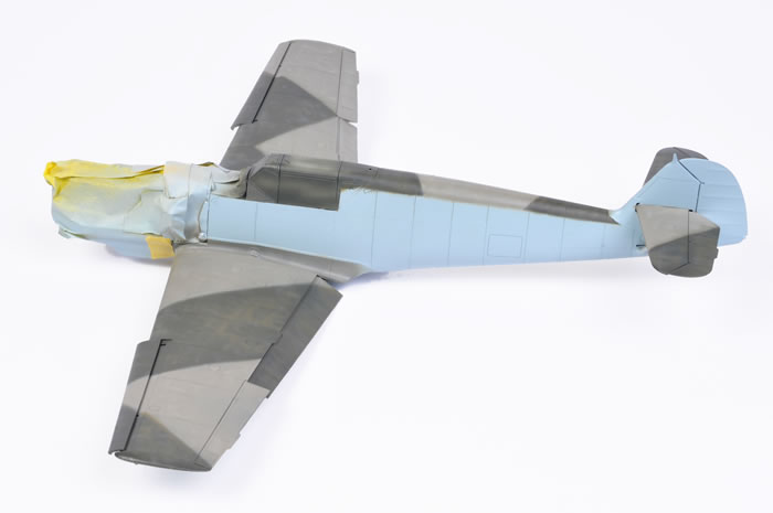
This aircraft was finished in the Phoney War finish of RLM 71 Dark Green and RLM 02 Grey with a very high fuselage demarcation line over RLM 65 Light Blue.
All paints were applied with my trusty Aztek A470 airbrush.
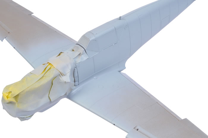
Eduard’s die-cut, self adhesive masks (included in the kit) were applied to the canopy, then the windscreen and rear section were glued into place. The centre section was a tight fit, but a few tiny spots of Blu-Tack were added to make sure that this clear part stayed in place during painting. The masks were fast to apply and conformed perfectly to the frames of the plastic canopy.
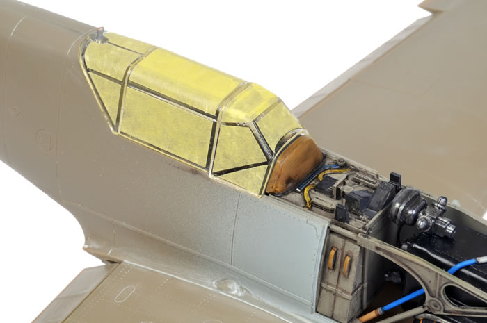
The first paint on airframe was RLM 02 Grey representing the interior canopy frame colour.
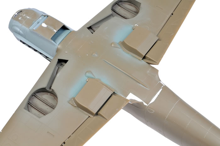
The model next received a base coat of Tamiya AS-5 Light Blue (Luftwaffe). To my eye, this ambiguously labeled colour appears to be somewhere between RLM 65 Light Blue and RLM 76 Light Blue, but is suitable for either.
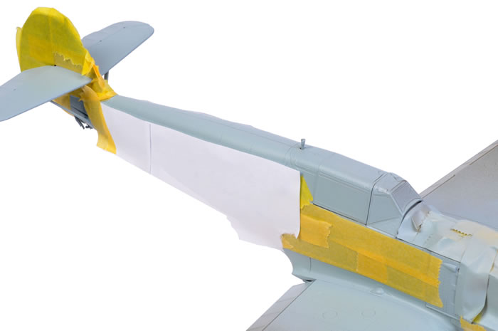
The upper surfaces received a coat of Gunze acrylic H70, RLM 02 Grey, broken up with some streaks and mottles of a paler shade of the same colour. This was quickly followed by a disruptive pattern from Gunze H64 RLM 71 Dark Green. The camouflage pattern was masked with paper held just off the surface of the plastic with small balls of Blue-Tack. This delivered a slightly feathered edge to the otherwise geometric camouflage pattern.
With the basic camouflage finished, Future floor polish was sprayed over the entire model. This tough top coat serves the dual purposes of preventing damage to the soft Gunze paint, and providing a useful sheen for the application of decals.
Markings, Weathering & Finishing Touches
EagleCals’ decals behaved flawlessly on application. The whites are bright, the red is convincing, and carrier film almost disappears even before the overall flat coat.
Gunze Flat acrylic was applied once the decals had set, then weathering commenced.
Panel lines were carefully built up with very subtle sprayed applications of a thinned black-brown mixture. This same black-brown mixture was sprayed along selected structural features and in random spots and streaks. Panel lines were then treated to a thin wash of Tamiya XF-18 Semi-Gloss Black paint.
The lower surfaces was dirtied of WWII fighters were often filthy from a combination of leaking oil, exhaust gas and dirt kicked up from unmade airfields. This grime was replicated with a combination of sprayed streaking and an oil wash.
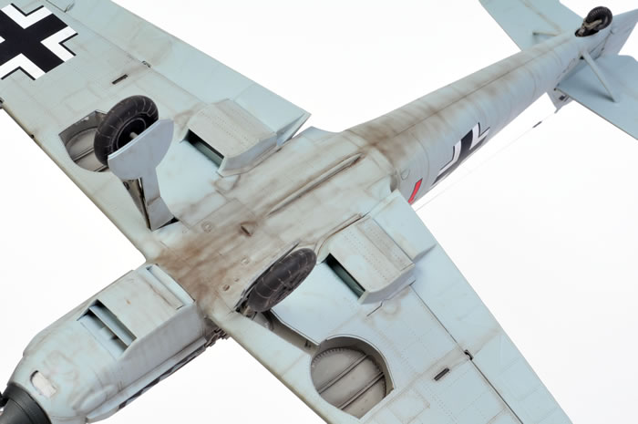
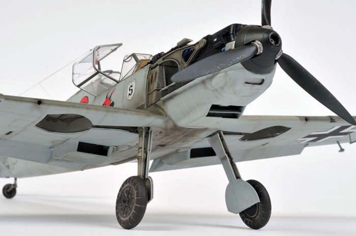
The smaller parts were painted and attached to the model. I was a bit concerned about the shallow locating lugs for the main undercarriage legs, but the fit was tight and the angle of the legs looked fine. I attached these with super glue for its fast setting qualities.
The kit's main wheels were weathered with Mig Pigments. The powder was mixed with water and brushed onto the wheels. When the pigments had dried, the excess was removed with a stiff brush.
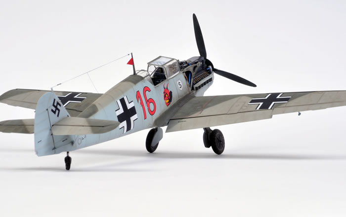
The small pennant on the aerial mast was cut from paper which had previously been painted red on both sides. The paper triangle was attached with Micro Krystal Kleer.
The aerial wire was cut from EZ Line, which was stretched between the fin antenna post and the mast, then secured with super glue. The lead-in wire was formed from stretched sprue. I find that stretched sprue is the best material for this task as it avoids the curling inevitably encontered with nylon monofilament or the thickness of un-stretched EZ Line. Isolators were added by building up small blobs of Krystal Kleer on the aerial wire.
Eduard has filled another important gap in the Luftwaffe modeller's repertoire with their 1/32 scale Messerschmitt Bf 109 E-1. At long last, we finally have a worthwhile large scale Emil.
Eduard's 1/32 scale Messerschmitt Bf 109 E-1 is very well detailed straight from the box, and the modeller has the choice of tackling the engine or simply buttoning up the cowl.
The kit is quite straightforward to build too, even with the engine on display.
This is another great kit from Eduard.
Thanks to:
-
Eduard for the review kit
-
Andreas Beck and Roy Sutherland for discussion about the fuselage "bulge" issue
-
Frank Crenshaw for pointing out the addendum photo-etched sheet and the tall oxygen bottle
Model,
Text Copyright © 2009 by Brett Green
Page Created 5 March, 2009
Last Updated
7 March, 2009
Back to HyperScale
Main Page |
 Home
| What's New |
Features |
Gallery |
Reviews |
Reference |
Forum |
Search
Home
| What's New |
Features |
Gallery |
Reviews |
Reference |
Forum |
Search