Review and Building Guide for
Silver Wings 1/32 scale
Hawker Hart
by Doug Nelson

Tamiya's 1/48 scale Spitfire Mk.I is available online from Squadron
When I decided to review the new Silver Wings 1/32 Hawker Hart, I thought about what kind of review I could do. I then remembered that the reviews I found most helpful were the ones in the old “Military Aircraft (later Model) Preview” magazine.
I liked that the models were unpainted, so that nothing was hidden by a nice paint job, and you could really see how everything fit. In retrospect, those reviews could have almost been considered a building guide as they also provided guidance and tips for the best way to assemble the model.
I then decided that if I were to do a kit review, I wanted to emulate that style of review. What follows is my attempt to do so.
Silver Wing’s 1/32 Hawker Hart is only their seventh 1/32 resin model kit, although based on the quality, one would think they had been at this for many years. Silver Wings has earned a reputation as one of the top producers of resin kits in general, and has become the undisputed leader in interwar aircraft models. As a fan of aircraft of this era, I was most pleased to learn of the release of this icon British interwar aircraft.
One of the fastest, and best looking, biplanes of its day, the Hart was so fast when it entered service that the fighters in service at the time could not catch it. The successful mutation of the basic design into a family of aircraft (Hart, Hart (India), Hart (Special) Hart Fighter, Demon, Osprey, Audax, Hardy, Hind, Hector, as well as the Swedish B4 attests to the excellent design of the basic airframe.
Note that the kit only provides parts to build the “original” Hart, and the builder will need to source their own modified parts to do any of the other family members. References on the Hart are surprisingly few and far between, but the most well known is likely the recent Mushroom Models Publications book “Hawker Hart Family” written by Alex Crawford.
For information and photos of the parts, please visit the Silver Wings website at: http://www.silverwings.pl/oferta.php?page=skala32_en
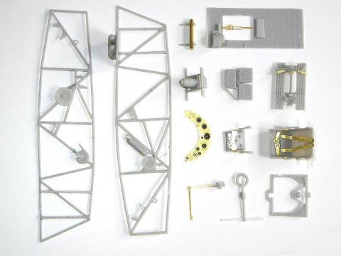
Parts Cleanup
Since they are not numbered, I decided to start this build by cleaning up all the parts. Immediately, I noted that the resin used for this kit is “softer” than resin I was used to dealing with. This made it much easier to do the parts cleanup since the parts were not as brittle. I was able to use my sprue cutter to clip all or most of the pour stubs from all the parts, and what remained just required a small bit of sanding with a sanding stick to finish. Overall, I think cleaning up these parts was easier than doing so for an injected plastic kit!
Things to note:
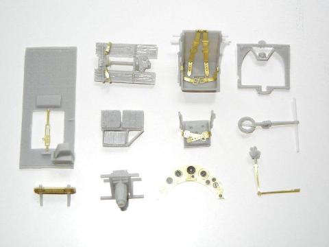
Interior Subassemblies
I began construction with the interior subassemblies. The instructions show these are a number of steps, each focused on one part of the interior. I encountered no issues with getting these completed.
Things to note:
-
When installing the lower seat brackets to the pilot’s seat, use two rods to position them correctly. You will need to line up the rod that goes through the top seat brackets with the top of the cockpit side frame, and then line up the lower seat brackets with the rod that goes into the forward hole in the bracket on the cockpit side frame.
-
You will need to drill a hole into the bottom of the control column to hold the cross-frame rod. I chose not to attach this to the floorboard at this time, rather attaching it during the building of the cockpit frame.
-
When installing the camera into its frame be sure to attach it oriented as shown in the instructions, noting that the frame is longer on the front side.
-
Review page 4 of the instructions, and attach items to the side of the frames as indicated. I ended up gluing another piece of frame to the port side frame to hold the radio gear frame and give me something solid to attach it to, and would recommend adding this to the portside frame at this point.
-
The PE provided is very soft, and bends very easily, even when you don’t necessarily want it to, so I advise that you do not cut the outer frame of the PE fret at all, as it will destroy the integrity of the fret making it easier to damage the parts, and only remove the needed parts with the tip of an Xacto blade.
-
The instructions do not provide much in the way of painting instructions; however, according to the Mushroom Models Publication’s “Hawker Hart Family”, it appears that the cockpit framing should be semi-gloss black or grey, with the pilot’s seat, floor boards in natural aluminum or grey, oil tank in grey, fuel tank in natural aluminum or grey. And instrument panel in grey with black instrument surrounds. Fuselage sides metal areas in grey or natural aluminum, with fabric covered areas in linen/tan or with red dope bleeding through. Padding color for the floor where the observer lays to use the bombsite color unknown, but likely black or leather colored.
Cockpit Assembly
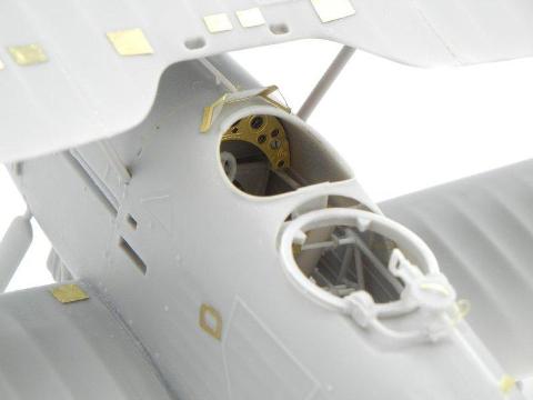
This proved to be the most challenging aspect of building this kit, so once you’ve got this part completed, the rest is easy J. Unfortunately, the instructions are not very clear on the location of some of the interior components. It is also easy to get the sides misaligned with each other resulting in a twisted cockpit frame assembly. The good news is that most of the cockpit frame is not visible in the finished model, so even if you end up with some twist, you can still fit everything into the fuselage (which will help untwist it some) and it will look fine when finished. For best results, I recommend the following order of assembly:
-
Glue the floorboard to the frame assembly with the compass, the rear set of tabs on the bottom of the floorboard should go on the front side of the compass frame and let set. These parts should be 90 degrees to each other.
-
Begin assembly of the fuselage frame by attaching the two 22mm and one 20mm seat frame/cross-frames (with the seats), as the provided holes should ensure that your frame is aligned. Next, also attach the 21mm cross-frame that attaches under the oil tank support, as that frame also goes into holes provided in the frame. Visibly ensure your frame is aligned and let set.
-
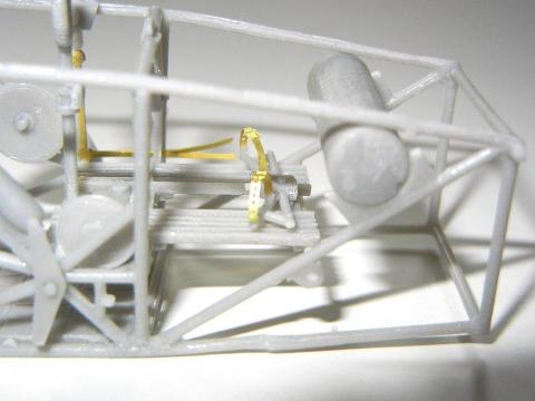
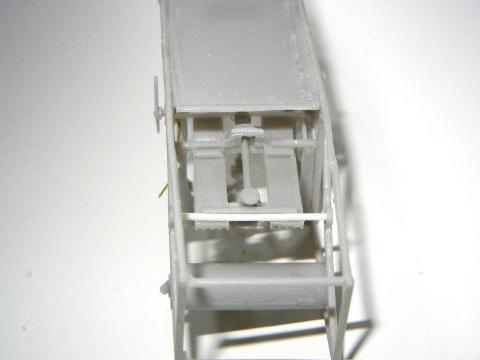
Attach the cross-frame with the control column in its place (in line with the bumps on the outer sides of the frames), and then insert the floorboard/compass assembly from #2 above. Note that the front tab on the bottom of the floorboard should rest behind the cross-frame you attached in #3 above. The rod holding the control column should be just under the read of the floorboard. If you will be adding the aileron control wires (the ones that go up in a “V” from the vertical “wheel” behind the control column), attach them at this point. The ends can be glued to the behind the instrument panel once it is attached at the end of this step.
-
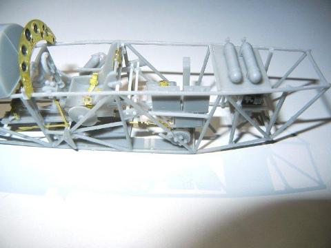
Attach the front 19mm and 18mm cross-frames to the frame. Check the frame alignment, and if good, insert and glue in the oil tank to the supports on each frame (see photo 7)
-
Attach the floor, ensuring that the hole is to the front, padding to the back (I installed my floor backwards and had to remove it later to correct this)
-
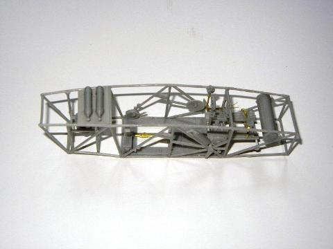
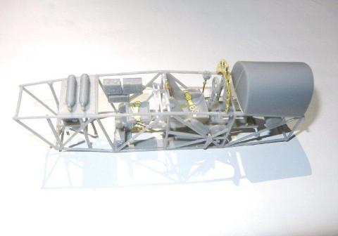
Attach the rear 14mm cross-frames, ensuring that both sides of the frames bend in the same amount. Once set, glue the shelf holding the two tanks into position.
-
Attach the camera into position, with the camera frame resting on top of the stubs on the fuselage side frames.
-
Attach the radio gear frame to the port side if you did not do so in the interior subassembly section above and attach the PE bulb (flare?) holder (PE21)
-
Attach the fuel tank, ensuring it is centered on the frame, and then attach the instrument panel. I put a couple small pieces of resin pour blocks on the frame to help hold the panel in place. At this time, you can run the aileron control cables up and attach them to the blocks (if you are installing them).
-
If you are installing the rudder and elevator control wires, do so now using the instructions to route them correctly. Note that these cables run on the outer side of both frames and should be mirror images of each other.
While this may seem complicated, you should be able to complete all these steps in 30 minutes or so. If you are worried about your ability to align your fuselage frames, another option is to line up both fuselage side frames, and either drill holes or notch the frames where the cross-frames should go while the two frames are aligned.
Other Subassemblies
In addition to the subassemblies needed to complete the cockpit, there are few others that can be completed as well.
-
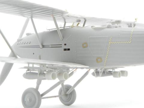
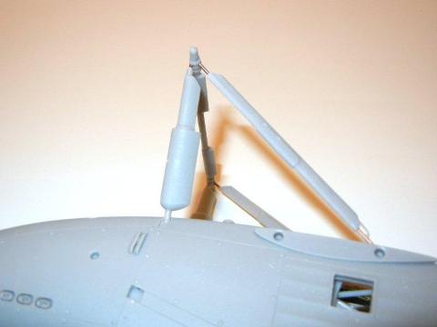
The Pott’s oil cooler can be assembled using 1mm rod to hold the PE parts. I did not worry about the lengths of the rods, and just drilled the locating holes in the bottom of the fuselage all the way through so that I could position it as desired. I would recommend not using the PE spacers between the cooling “leaves”, as they are too thin and would instead punch some similar sized discs from 5 thou sheet styrene so that the “leaves” are spaced a bit more like the real thing. Note that some Hart (India)’s had Potts coolers with 9 “leaves” instead of 5, so if the airframe you are modeling has 9, you will need to make some additional “leaves” out of 10 thou sheet styrene to fill in between the PE ones.
-
The bomb racks and bombs can be assembled as a unit, and then attached to the lower wing once the model is completed (mine fit so well I could click them into the holes without glue) since it will be easier to place the serial number decals on the bottoms of the wings without them attached. I did note that some of my bombs were missing a section of one of the three fins. If your kit is the same, you can add the missing part using sheet styrene. Also be sure to note that the front and rear brackets are different, and that the wider bracket goes toward the front. You can leave the bombs off the racks until final assembly if you wish.
-
You can assemble the gunner’s scarf ring and MG at this point, or wait until the fuselage is assembled if you wish to test fit it before assembly. I am not sure about the site on the front of the gun, but it looks good there nonetheless.
-
If your model carried radio equipment, drill holes in the appropriate locations on the upper wings and rudder. Fabricate the attachment posts out of some styrene or metal rod, and install them at this point, or wait until you have painted and decaled your model.
Fuselage Assembly
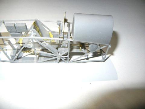
Fuselage assembly is straightforward and should not present any issues. My sample did have some slight warping inward on the bottom of the fuselage around the cutout for the bomb aimer. Fortunately, being resin, simply pouring some hot water on it and then bending back into shape worked fine. If at the end of the previous step, your cockpit subassembly ended up with a slight twist, you should still be able to fit it correctly in the fuselage following the directions below.
-
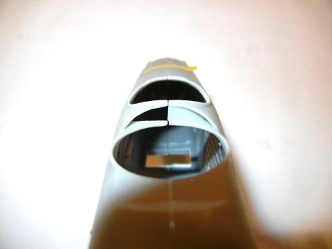
Install the exhausts into the fuselage, note that they are “handed” so that each goes into its proper place.
-
Test fit the air intakes (“L” shaped parts that go on top of the fuselage), but do not glue them into position
-
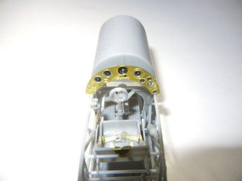
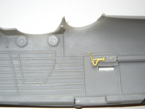
Attach the MG breech assembly to the fuselage side, and attach the PE charging handle and attach the ammo drums . Although not noted in the instructions, each ammo drum should have a PE handle (PE20) installed.
-
Install the firewall bulkhead to one fuselage half, and test fit the opposite half to ensure proper alignment.
-
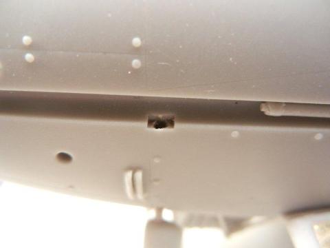
At this point you can test fit your assembled cockpit into the fuselage. You may see that it fits so well that you can simply glue the fuselage together and it will be in the proper position. However, if it does not fit well, then separate the fuselage halves, and attach the cockpit to one side, using the locator tabs provided. Let set, and then attach to the opposite side, while gluing the fuselage together. You may need to prod or poke it with a toothpick to get it into the proper position. Looking at the bottom, the
-
Once the fuselage glue has set, you can clean up any seams by sanding. My sample had a bit of a seam along the bottom (top was perfect), however the superglue I used to join the fuselage filled it nicely. Once complete, you can attach the air intakes; PE hand holds (PE8); and the MG barrel. You may wish to use one of the fine Master brass barrels instead of the supplied part for a crisper look.
-
The kit provides PE fabric stitching, which I have attached to my model. However, you may wish to skip this step as I have only seen one photo (of a museum airframe) where it appears you can see this stitching. However, should you wish to add it, you can use the provided stitching, which should look very nice after a coat of primer. As an alternative, both Archer transfers and HGW offer alternative, easy to use, stitching as well.
-
You can attach the sliding bomb-aimers door to the bottom of the fuselage in either the open or closed position.
-
Attach the tailskid and rudder post cap at this point.
-
At this point, using the resin part of the gun sight tube, I marked the locations for two holes for the attachment points and drilled them out. After a successful test fit, I removed the tube and attached the PE beads and sight. I then set this part aside until final assembly. You can attach it at this point, as getting it in with the wing in place might be tricky, but I was more concerned about damaging it when fitting the heavy upper wing.
-
I cut out the windscreen PE and acetate part and bent the PE part into the correct shape. Note that the tabs on the lower side panels should be angled downward slightly to help get a better fit. Once I was happy with the PE fit, I lightly scored the acetate piece with a hobby knife on the two lines where it needs to bend to help it bend and stay in position. I recommend dry fitting the acetate, and then when you are satisfied, attach only the PE part to the fuselage, and attach the acetate piece after final painting.
-
Lastly, you can attach the film window on the starboard side (or you can wait until after final painting) and the pilot’s headrest behind the seat. Do not attach the venturi tube, gun sight mechanism or windscreen at this point, as they may be damaged when attaching the other major airframe components.
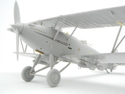
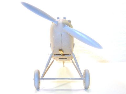
Landing Gear
The landing gear, although it looks delicate, is surprisingly strong – which it must be as the completed model weighs about 250 grams (or just over ½ lb). As the instructions are not clear on how to assemble the components, I consulted my references and discovered that the main struts attach at the front of the axel tube, and the supporting struts attach at the upper-rear of the axel tube.
-
First, make sure that your axel tube has any cooper wire sticking out of the ends removed, so that it is flush with the resin wheel attachment point.
-
Using a #66 (.033) drill bit, drill out the main gear strut attachment points on both sides of the fuselage. Test fit your main gear struts (do not trim any of the copper wire from the top side as it will give added strength to the gear assembly). Next, using the same drill bit, widen the outermost slot on the front edge on each side of the axel tube, making sure to keep the holes aligned. Test fit the axel tube to the test fitted main gear struts.
-
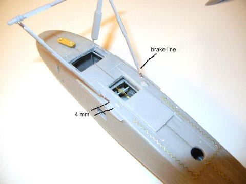
On the bottom of the fuselage, there are two indentations that appear to be for the ends of the support struts. Unfortunately, these indents will not allow the supporting strut to fit properly. Again, using the #66 drill bit, drill a hole 4mm in front of the indent and at an angle towards the test fitted main gear strut and axel tube. Test fit the support strut and repeat for the opposite side and be sure the brake lines are on the side facing away from the fuselage.
-
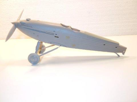
If everything fits and is aligned correctly, you can glue the landing gear in place.
-
Test fit the main wheels and admire your work J
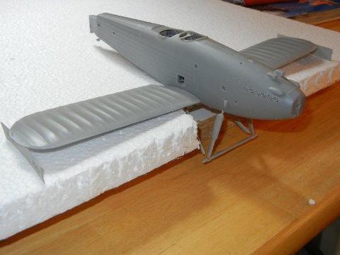
Lower Wings
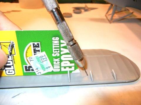
Before attaching the lower wings, you may want to test fit your radiator, and sand the mating surface as needed to ensure that the brackets fit properly. Once you are satisfied with the fit, you will want to drill out the interplane strut attachment holes at a slight angle outwards and forward. If you wish, you can make a drilling angle template from a piece of cardboard using the drawing on page 8 of the instructions. You may also want to drill out your rigging attachment points, depending on your rigging method of choice. Note that the Hart, like many British biplanes of the Interwar era, did not use external turn buckles, rather these were hidden beneath the surface of the wing.
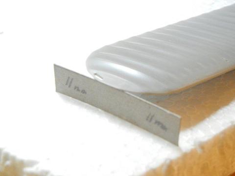
Test fit each wing to the fuselage. Once you are satisfied with the fit, you are ready to attach them. The instructions kindly let us know that the bottom side of the wing tip should be 11mm higher than its attachment at the fuselage. An easy way to ensure proper fit and dihedral is as follows.
Using an old kit box, or some other thin cardboard, cut two 11mm strips. Then, using some old styrofoam; Legos; or your favorite jig material, set up your jig so that your landing gear will not interfere with your fit. Test fit both wings, and slide your 11mm cardboard strip into place under each wing tip. If all looks correct, remove the wings and glue one wing into position, sliding your 11mm strip under the tip. Once this wing has set, repeat the process for the opposite side.
Struts
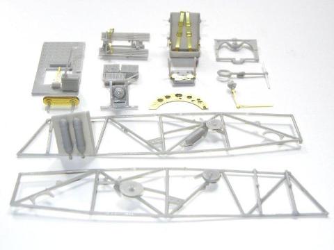
Now is a good time to familiarize yourself with the struts provided in the kit.
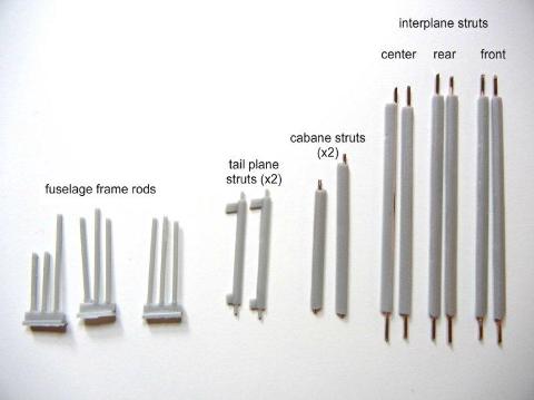
You can see we have interplane struts (wing-to-wing); cabane struts (upper wing -to-fuselage) and tailplane struts. Note that the tailplane struts are different lengths, with the two longer struts being the forward pair, and the shorter the rear pair. The same applies to the cabane struts, the longer pair go forward, and the shorter pair go towards the rear. With the interplane struts, the 2 shorter struts are the middle almost vertical struts, with the remaining 4 being the forward and rear struts as indicated (note the slight difference in the notch at the end of the strut – which faces the middle strut where they attach).
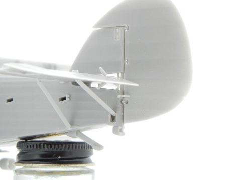
Rear Empennage
The tailplane and rudder can be attached at this point, or after you have attached the upper wing (or even later if you need to paint stripes on your rudder). Depending on your material of choice for the control lines, you can either attach them to the fuselage at this point, or after painting/decaling. You may want to drill some holes in the horizontal stabilizer where the control lines attach to make it easier to do so, as well as drill holes for the rigging material of your choice.
-
The instructions indicate that when you attach the main horizontal stabilizer, the vertical stabilizer has a rod that should fit in an indent at the back of the horizontal stab. However, I found that if I aligned these two parts, there was a bit of a gap at the front of the horizontal stab. I enlarged the hole a bit towards the rear, and everything fit fine. Note that there is a small post that needs to be placed between the fuselage and the horizontal stab, aligning with the aforementioned rod on the vertical stab. You may wish to drill out the hole for this rod in the fuselage, and place a longer than necessary rod in the hole. You can then pull it up from the fuselage to attach it to the horizontal stabilizer, ensuring a perfect fit without the need to measure.
-
With the horizontal stabilizer in place, you can now attach the support struts. As mentioned above, the two longer struts are the forward ones, and the shorter ones are the rear. I cut the attachment pins off the bottom of the two rear struts, as they meet inside the hole in the fuselage. I did find that I needed to keep the all the pins on the forward struts; otherwise they would have been too short.
-
Once the main horizontal stab is on, you can attach the control surfaces. Don’t forget to attach the control horns to the elevators and rudder prior to attaching them to the rest of the rear empennage. Photo 23 shows the completed rear empennage.
Upper Wing
This seems to be the part that most modelers, in particular those who have not built a biplane, dread. It is really not that difficult to do, provided you plan ahead a bit. There are many different ways to go about attaching the upper wings, but I will just review the way I did it for this model.
-
First, I drilled out the holes for the cabane (fuselage to wing center) struts in the wing center piece. Although the kit appears to be designed for you to remove the copper wire pins on the parts of the struts that attach to the fuselage, I wanted to keep a bit of the pin for added strength, so I drilled out holes in the attachment slots (photo 24). I then trimmed the pins on the cabane struts to fit. I then test fit the center wing and cabane struts to the fuselage. After a small amount of tweaking, the fit was good.
-
I then removed the center wing section (and cabane struts) and cleaned up the mating surfaces of the center and outer wing sections. I then used an angle template to drill the appropriate holes in the outer wing section for the interplane struts. This would also be a good time to drill the appropriate holes for the rigging method of your choice (don’t forget the holes in the fuselage and bottom of the upper wing for the aileron control cables!). The instructions provide that there should be 3mm of dihedral at the tip, so, like with the lower wing, I made some cardboard strip templates and used them to ensure the proper position.
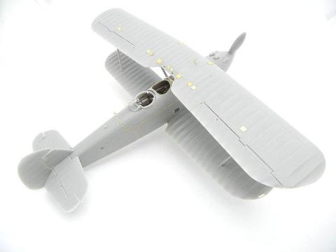
-
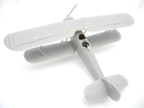
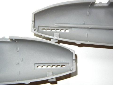
At this point, you can attach all the PE inspection panels to the top side of the upper wing (and the two on the lower wing) per the instructions.
-
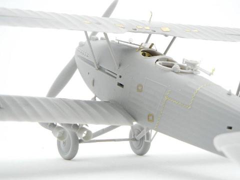
Once dry, I again test fit the upper wing assembly to the fuselage using the cabane struts only. They are so strong that they easily support the very heavy (100 grams/almost ¼ lb) wing (photo 25).
-
I then removed the wing, installed the model in my wing jig* and using some slow-setting superglue gel (or epoxy) to give myself time to position them, attached the cabane struts to the upper wing, and then the wing and struts to the fuselage. I checked the alignment and then let the assembly dry overnight.
*you can use an actual jig; Legos; or cardboard, etc. to make your wing jig – it does not need to be fancy, as it’s only purpose is to ensure the same distance on both sides between the upper and lower wings, and that the upper and lower wings are aligned with each other.
-
I then test fit the interplane struts and using the same slow-setting superglue gel, attached them to the upper and lower wings and once I was happy with their position, left everything to dry overnight.
-
Attach the 3 slat actuators to the port and starboard underside leading edge of the upper wing. The end with the post goes towards the rear, and fits in the hole provided.
-
I then attached the control rods to the ailerons and attached them to the upper wing (they fit snuggly in position with no glue needed)
Final Assembly
Now we just have to attach the remaining small bits, and the model should be done.
I would recommend painting decaling and rigging your model (if you prefer to rig after painting/decaling) at this point (don’t forget the control lines for the ailerons, elevators and rudder). Once completed, attach the final parts as follows:
-
Attach the acetate window to the pilot’s windscreen using your favorite clear parts glue. If you have not yet attached the acetate side window, do so now.
-
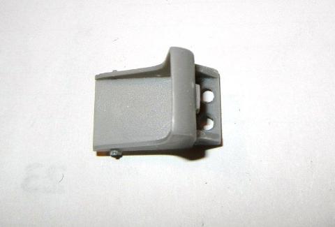
You can now attach the Pott’s oil cooler, venturi tube and boarding step to the bottom of the fuselage.
-
Glue the radiator and its brackets into position.
-
Attach your bomb racks (and bombs if you wish) to the bottom of the wings.
-
If you have not already done so, attach your radio antennae posts if appropriate for the airframe you are modeling. Also attach the radio insulator to the upper fuselage.
-
The kit provides a PE pitot tube assembly, and you can attach this to the forward strut on the port side of the aircraft. I would recommend building up the shape of the flat “tube” sections to a round shape, or replace them with styrene or metal tubing.
-
Fold the PE gas tank vent (PE9) in half, or preferably create your own from metal or styrene tube/rod, and attach to the upper wing tank per the instructions.
-
Attach the gunner’s scarf ring assembly to the model.
I hope that you have found this review/build guide helpful. Look for a review/build guide on the Silver Wings 1/32 Gloster Gladiator I/II in the near future!
Model, Images and Text Copyright ©
2011 by Doug Nelson
Page Created 20 September, 2011
Last Updated
20 September, 2011
Back to HyperScale Main Page

|
 Home
| What's New | Features | Gallery | Reviews | Reference | Resource Guides | Forum |
Home
| What's New | Features | Gallery | Reviews | Reference | Resource Guides | Forum |