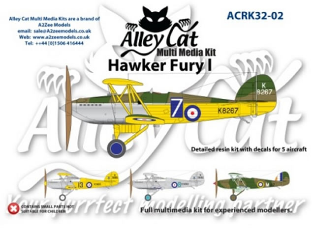
Alley Cat 1/32 scale
Hawker Fury Mk.I
by Roger Hardy
 |
Hawker Fury Mk.I |

Airfix's 1/72 scale Spitfire Mk.22 is available online from Squadron
S
u m m a r y |
| Catalogue Number: |
Alley Cat Kit No. #ACRK32-02 - 1/32 Hawker Fury Mk I with GasPatch turnbuckles |
| Scale: |
1/32 |
| Contents and Media: |
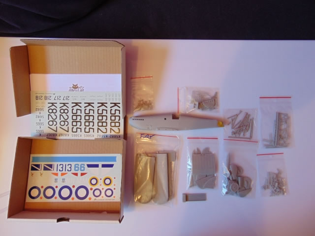
Multi-media resin kit with white metal parts and five marking options. |
| Price: |
Purchased online from Hannants for £96.00 plus shipping |
| Review Type: |
Build Review |
| Advantages: |
Appears accurate, highly detailed; great fit; nice surface detail treatment |
| Disadvantages: |
Instructions are basic in the extreme. |
| Conclusion: |
Highly Recommended. |
 History History
The Hawker Fury was a British biplane fighter aircraft used by the Royal Air Force in the 1930s. It was a fast, agile aircraft, and holds the distinction of being the first interceptor in RAF service to capable of more than 200 MPH. The Fury is the fighter counterpart to the Hawker Hart light bomber.
The Hawker Fury was a development of the earlier Hawker F.20/27 prototype fighter, replacing the F.20/27's radial engine with the new Rolls-Royce F.XI V-12 engine (later known as the Rolls-Royce Kestrel), which was also used by Hawker's new light bomber, the Hawker Hart. The new fighter prototype, known as the Hawker Hornet, first flew at Brooklands, Surrey, in March 1929. The Hornet was a single-engined biplane, with single bay wings, initially powered by a 420 hp (313 kW) Rolls-Royce F.XIC engine enclosed by a smooth, streamlined cowling, but was quickly re-engined with a 480 hp (358 kW) Kestrel IS. It was evaluated against the similarly powered Fairey Firefly II, being preferred because of its better handling and its all-metal structure compared with the mainly wooden construction of the Firefly.
The Hornet was purchased by the Air Ministry at the start of 1930, and was subject to further evaluation, with a small initial production order for 21 aircraft (to be designated Hawker Fury - as the Air Ministry wanted fighter names that "reflected ferocity") placed during 1930. The Fury I made its maiden flight at Brooklands with chief test pilot George Bulman at the controls on 25 March 1931.
The Fury was the RAF's first operational fighter aircraft to be able to exceed 200 mph (322 km/h) in level flight. It had highly sensitive controls which gave it superb aerobatic performance. It was designed partly for the fast interception of bombers and to that end it had a climb rate of almost 2,400 ft/min (730 m/min, powered by a 525 hp/391 kW Kestrel engine).
The Fury I entered squadron service with the RAF in May 1931, re-equipping No. 43 Squadron. Owing to financial limitations owing to the Great Depression, only relatively small numbers of Fury Is were ordered, the type equipping only two more squadrons, 1 and 25 Squadrons. At the same time, the slower Bristol Bulldog equipped ten fighter squadrons. The Fury II entered service in 1936-1937, increasing total number of squadrons to six. Furies remained with the RAF Fighter Command until January 1939, replaced primarily with Gloster Gladiators and other types, such as Hawker Hurricane. After their front line service ended, they continued to be used for training purposes.
The Fury was exported to several customers. Three Furies were ordered by Spain in 1935, it being intended to produce another 50 under licence. The Spanish variant had a cantilever undercarriage design with Dowty internally sprung wheels, similar to that used on the Gladiator, and was powered by a 612 hp (457 kW) Hispano Suiza 12Xbr engine, reaching a speed 234 mph (377 km/h). The three Furies were delivered without armament on 11 July 1936, just before the outbreak of the Spanish Civil War. They were taken into service by the Spanish Republican Air Force, being fitted with machine guns scrounged from crashed aircraft. One Fury made a forced landing behind enemy lines due to a lack of fuel and was repaired by the Nationalists, although it was not used operationally, while the Republicans used one of the Furies in the defence of Madrid until wrecked in a crash in November 1936.
A total of 262 Furies were produced, of which 22 served in Persia, 3 in Portugal, at least 30 in South Africa, 3 in Spain, at least 30 in Yugoslavia, and the remainder in the United Kingdom.
There is one surviving Fury that has been restored to flying condition. A Hawker Fury Mk I, serial number K5674 , is owned by the Historical Aircraft Collection and based at the Imperial War Museum Duxford in the United Kingdom. This aircraft was delivered to the RAF in 1935 and allocated to 43 Squadron, where it was flown until 1939 by Flying Officer Frederick Rosier, later to be Air Chief Marshal Sir Frederick Rosier. In 1940, it was sent to South Africa where it was flown by 13 Squadron (later 43 Squadron) of the South African Air Force. It was written-off after making a forced landing, due to running out of fuel. It was returned to the United Kingdom in 2003 and restored to flying condition, with the civil registration G-CBZP. It made its first post-restoration flight in July 2012.
The Kit
This kit was originally issued by Montex but has now been re-issued by Alley Cat with some improvements, such as decals and white metal parts. It is also cheaper, though perhaps I should say ‘lower cost’.
Even so, it costs little more than a Wingnut Wings offering. I understand that the pattern maker, Wojtek Kuakowski, is now the man behind the lovely ‘Silver Wings’ models from Poland, so things look good. The quality of the grey resin castings approaches the standard of the best injection-moulded kits and there are even locating pins in the important places. I didn’t notice a single air bubble and only needed to trim a little moulding flash here and there, but this is expected. The fabric-covered surfaces are particularly well done with rib detail being nice and subtle, just like a real aircraft.
A brief review of the Montex release was published here:
http://www.hyperscale.com/2010/reviews/kits/acrk3201previewbg_1.htm and here:
http://www.hyperscale.com/2008/reviews/kits/montexpreviewbg_1.htm.
The kit I built is Option 2, training schemes (Option 1 being identical except for the markings which are for operational aircraft), and consists of a multitude of resin parts and white metal struts. There is no photo-etch fret and no Sutton seat harness, the only thing this kit lacks, but Eduard produce one for those who are too lazy to make one from scratch (like me). The quality of the mouldings is wonderful with a realistic rendering of ribs and fabric. The major components have already been removed from the casting blocks and cleaned up so you only need to worry about the little fiddly ones. Decals are provided for five aircraft, two trainers from RAF Cranwell, two South African Air Force and one RAF camouflaged trainer. The instructions are basic but this model is intended for experienced modellers who apparently don’t follow instructions in any case.
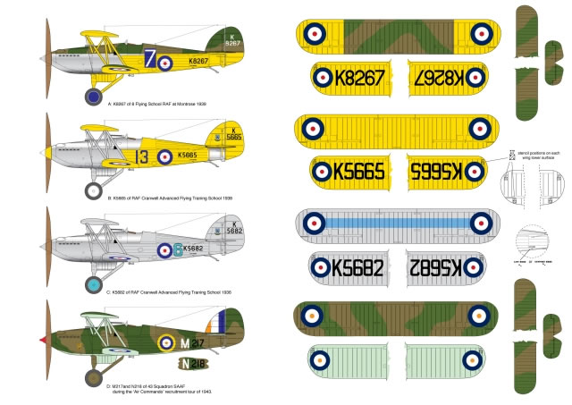
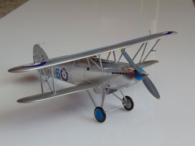
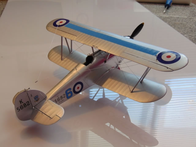
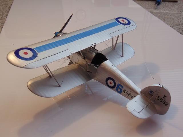
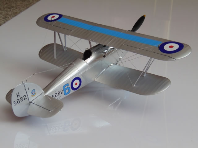
My intention was to model the Fury in one of the less usual colour schemes; 43 Squadron’s black-and-white checkerboard markings are just so passé these days! I fancied the RAF Cranwell aircraft (I was a cadet there in the late 60s) and was torn between the yellow bird and the all-silver one with light blue details. In the end, I opted for the latter so that I could experiment further with Alclad metallic finishes. I am certain that the RAF College aircraft would have had highly polished noses!
Alclad do some finishes that are ‘highly polished’: chrome, polished aluminium, etc. I have never had much luck with the latter but ‘chrome’ looks great…actually just like highly polished aluminium when sprayed onto a gloss surface but normal silver when sprayed onto matt, so these finishes depend totally on the quality of the surface underneath. If the primed surface is matt, the finished effect is totally different from when it is gloss, when it really shines. Also, the tone of the metal effect depends on the colour underneath; gloss black gives a totally different effect to gloss grey as these paints allow the base colour to come through to some extent. So, my plan was to use Tamiya grey primer for the fabric-covered parts but gloss mid-grey for the polished metal panels of the nose. The result should then be painted fabric and a realistic polished aluminium front fuselage. Another reason to try to get a two-tone effect from one basic colour is that you cannot mask these highly reflective finishes but you can mask the underpainting to get the same effect.
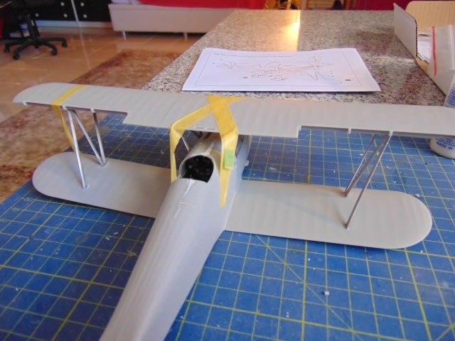
The instructions are slightly confusing initially, as the first thing you read is recommendations on dry-fitting the upper wing to the fuselage. These notes are possibly an afterthought and I took their recommendation to drill out the small holes 1.5mm and check the assembly of the centresection and upper wing.
ncidentally, the hole centres are all marked but under the centresection six are marked whereas you only need four. This is because the original Montex release had separate struts, not V struts. Anyway, long story short, you need to drill out the front and rear holes only. I was expecting something very approximate in terms of fit but was pleasantly surprised that all of the parts clicked together rather well. The resin is, incidentally, soft and easy to work but be careful that you only drill deeply enough to accept the strut locating pins and not right through the wings! Remember to wash the resin parts in warm soapy water as the release agent used with resin moulds is particularly effective in resisting glue and paint. The wings have metal pins moulded into them to ensure strong joints. The wingtips (upper and lower) have what look like housings for navigation lights, but these are blow-holes to avoid air bubbles in the moulding process and should be removed.
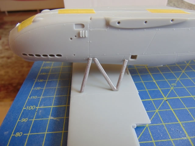
The first stage of the construction is the most important as it sets the entire geometry of the wings and fuselage. First, you drill out the strut attachment holes with a 1.5mm twist drill, then trial assemble the upper wing assembly to the fuselage. I assembled the upper wing, taping the centresection to the work surface, cutting the dihedral jig (a little 3mm spacer to place under the inverted top wing) into two and using the two halves to support the wingtips to ensure the same dihedral on each outer wing. The wing is fitted with locating pins (which break) and brass rod (which doesn’t) but I found that they were slightly incorrectly positioned and had to enlarge the holes for the brass rods to get the best fit. Then the fuselage is fitted with the V cabane struts which are inserted in the holes under the centresection. The rear fuselage tailplane rebate is raised 25mm from the work surface and the front cabane struts are fitted. The instructions recommend superglueing the cabane struts to the fuselage at this point, which I did. I found that it was best to elongate the rear holes of the centresection to allow for correct alignment of the fuselage and wing (ie, fuselage at right angles to the upper wing). The cabane struts ensure the correct incidence of the upper wing. In addition, I found that gel superglue worked best for these big assemblies because of its gap-filling properties. In theory, the entire wing geometry is now fixed.
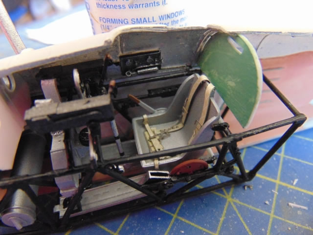
Cockpit (construction Stages I – III)
Next comes the cockpit and I would have appreciated some colour call outs on the instructions. The build review at Britmodeller, http://www.britmodeller.com/forums/index.php?/topic/234926313-alley-cats-montex-fury-i-132/ refers to the Nimrod and has the tubing in semi-gloss black and the rest in aluminium, fuel tank in steel, elevator trim wheel in red (should be wood brown) and hand pumps in brass.
The cockpit walls appear to be silver where the skin is metal and dull brick red where it is fabric.
From another Britmodeller forum:
“The interior of the cowls was obviously natural aluminium. The tubular structure was either black or interior grey green (depending on year of construction), instrument panel was anodised grey aluminium and the seat painted in aluminium paint. The rear plywood bulkhead behind the pilot's seat was usually painted grey green (I would treat the interior frame as being grey-green with caution. Either japanned black or aluminium dope I'd suggest).”
And this from Retrotec who rebuilt the Duxford Fury:
-
"The interior of the Fury is as follows:
-
The steel tube and steel fittings are stove enamelled black.
-
The stainless steel fittings are bare metal.
-
The Duralumin parts are anodised grey.
-
The aluminium cowlings are polished.
-
The wooden parts are painted cockpit green.
-
The fabric appears red on the inside; this is the colour of the first coats of dope (showing through the fabric).”
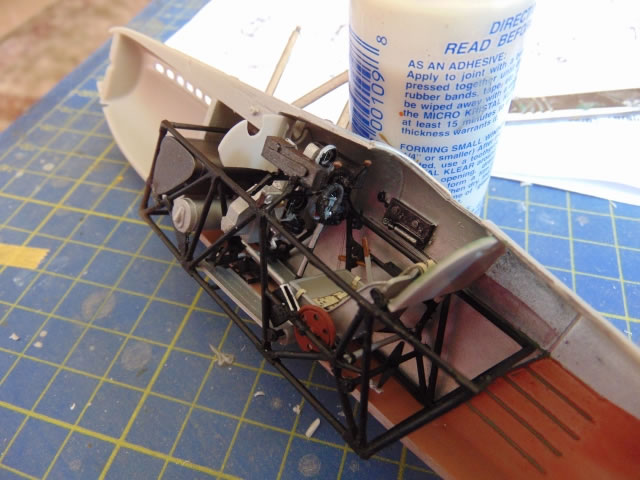
I was concerned about breaking these fine resin cockpit parts but need not have worried; the grey resin is quite flexible and not brittle like the buff-coloured stuff. The instructions are, again, rather approximate when it comes to the assembly of the rather detailed cockpit. On that subject, the cockpit interior is very comprehensive and reminiscent of a Wingnut Wings model, which is to say that it’s all there, it’s all perfect but a lot of it will never be seen again! Putting these very fine details together is rather easier with resin than with plastic because the superglue bond is instant; all it takes is accurate positioning with tweezers. What was difficult was to identify all the millions of tiny parts which seem to be spread at random throughout six sealed plastic bags. Alley Cat have missed a trick here and it would be easy for them to put all of the resin parts for each assembly stage (there are only 6 stages) in the same bag to make life easier. I would also suggest making the assembly artwork a bit clearer to eliminate the guesswork; for instance – where exactly does the seat go? And all those throttly things…inside or outside the frame? I referred to the Britmodeller topic when in doubt but it should not be necessary if the instructions were a bit more helpful (actually, it’s always a good idea to refer to the next drawing in the instructions as it shows the correct locations).
The next annoying bit is that I noticed that there were plenty of duplicates of parts; providing two when only one was needed. That’s nice, I thought. The downside is that there are also parts that are needed that aren’t there, so Alley Cat needs to pay more attention to its quality control. You don’t realize this until you’re sorting through all the bits and pieces trying to identify which goes where. Of course, with these kits, there are no nice neat sprues to check and no illustrated parts breakdown, so no way of telling what’s not there until you can’t find it. I resorted to scratch building the missing parts but had to contact Alley Cat for the instrument panel film. Moggie-in-Chief, Alistair Maclean, got one in the post to me the same day. Thanks! Incidentally, one of the many extraneous bits not mentioned in the instructions is a lever for raising and lowering the seat and this should go on its right-hand side. It seems a shame for such a good quality model to be let down by quality control and poor instructions when a little more effort could rectify the situation. I don’t expect a Wingnut Wings glossy manual but a bit more thought would have been nice. There’s a real Fury and a real Nimrod out there to photograph. Modern digital cameras and colour printers can do it…so can Alley Cat!
Having assembled the cockpit interior I tried it inside the fuselage, half expecting fit problems. Actually, there were none and the interior fits very nicely. I added the Eduard 1/32 Sutton harness (actually labelled ‘RAF WWII harness’) but it’s a Sutton. At this stage the basic cockpit is done but still lacks the instrument panel and guns but, already, I am reminded how much like a WWI fighter the Fury is; the cockpit is so similar to a Fokker DVII! Also, like the Fokker, not that much can be seen inside but the Sutton harness looks great!
The installation of the guns is, again, rather approximate and it would have been a good idea to have some ordered sequence to get this right as the rear gun mounting frame more-or-less defines the location of the guns.
Stage IV
This stage installs the cockpit assembly and seals up the fuselage. The shell chutes are nicely formed. You have no choice but to insert the exhausts at this stage and as I can see no way to mask them they will require very careful hand-painting after the model is sprayed. Putting the fuselage halves together was easy as there are locating pins but it is clear that some filler will be required along the seams, especially the lower fuselage, but this is to be expected. Do not install the rear pillar (which determines the location of the rear of the tailplane) as it is very fragile and will break off. Install it when the tailplane is mounted.
Stage V
This stage assembles the lower wing, struts and tail unit. If you’ve followed the initial instructions, you’ll already have fitted the cabane struts, so I guess this is a reminder in case you forgot. I trial-fitted the lower wings and - whoops! - they had anhedral (they bend down, not up). Ok, so a bit of drilling out the location pins as the lower wing dihedral should be set by the correct dihedral of the upper wing. I attached the upper wing to the cabane struts and taped it into position then experimented with the interplane struts. These are marked A, B, C and 1, 2, 3 to identify left and right as well as front, diagonal and rear. Unfortunately, these markings are difficult to read but correct identification is important. The short diagonal is easy to identify and of the other two struts, the rear strut is slightly longer. By taping the wing tips, it is possible to install all of the interplane struts, check the wing alignment, then use gel superglue at the strut attachments to the lower wings to fix the wing geometry without permanently mounting the upper wing; this makes it easier to spray the model later with the upper wing off. Again, this process was far easier than I had expected as each unique strut has pins that have been orientated correctly for each individual position.
Please note that each strut can only fit one way and you really need to think about this as the geometry is complex. If they don’t appear to be fitting well, you’ve probably orientated them incorrectly or your dihedral is wrong. If you feel you need to significantly trim any of these struts and your dihedral is correct you have one or more of them in the incorrect orientation. Get this right and the model is easy. Get it wrong and you have problems. Once all the struts are in position, glued into the lower wings, free-floating in the upper, tape up the wing assembly to let the superglue set thoroughly. Incidentally, if you’ve got the dihedral wrong and you’re having to strain the wings to get the struts to fit, go ahead and tape everything up, then get a hot hair dryer and heat up the offending wing which will then soften slightly and correct itself.
Incidentally, although I had achieved perfect fits of the struts and wings during trial assemblies, when I came to gluing everything together I found that the forward interplane struts stood a little proud of the holes where they were meant to be glued. Don’t force them! The struts are weak and you’ll end up with a collapsed wing assembly! I found that I could get a better fit if I joined the two rear strut holes in the upper wing lower surface because it cannot be seen and allows for any mismatch in the two pin locations of the rear struts. So, my recommendation is to have round holes at the front and long holes at the back. You don’t want to be messing around with this after it’s painted!
Overall, I have to say that I found these white metal struts rather soft and definitely prefer the Silver Wings approach of casting the struts in resin around brass rod.
I installed the tailplane and fin next; the correct location for the tailplane is to butt the front against the edge of the rebate in the rear fuselage with the rear of the tailplane supported by the pillar that sticks up out of the rear fuselage (there’s a locating hole under the tailplane), and then ensure that the fin rests on the tip of the tailplane. This leaves a triangular gap under the tailplane and the tailplane struts confirm this position as correct. For the correct location of the fin, put the little tail bumper in place and you can work it out. The fin is anchored where it butts against the rear fuselage and the top of the tailplane. All of this could have been made a lot clearer in the instructions. but I’m starting to sound like a broken record.
Stage VI.
The undercarriage is simple but you need to be careful drilling the 1mm holes in the strut attachment points on the insides of the wheels as the resin is fine and easy to break. It would have been better to have eliminated the complex resin triangulating structure moulded into the wheel and leave it up to the white metal parts, then the wheels could also be left off until after painting. It is not possible with this model to leave the wheels off until later and definitely no rolling wheels! Again, it self-jigs well. Incidentally, my example had the wheel spats sometimes fitted to the Fury Mk II as well as a tailwheel as fitted to the two airworthy examples in UK and as occasionally fitted to training aircraft, even Fury Mk Is, although I could find no photos showing this. I reinforced the tailskid with 0.5mm brass rod because it looked impossibly fragile and certain to break. (Postscript: even reinforced, I managed to bend it several times during masking/spraying and I’d now recommend leaving it off until the model is finished). There are no photo-etched parts so every tiny little detail is provided in resin. For parts such as control horns, resin is really too brittle and it’s probably better to replace them with plastic card and brass rod. I made a ring sight from fuse wire.
Painting, Markings and Rigging |
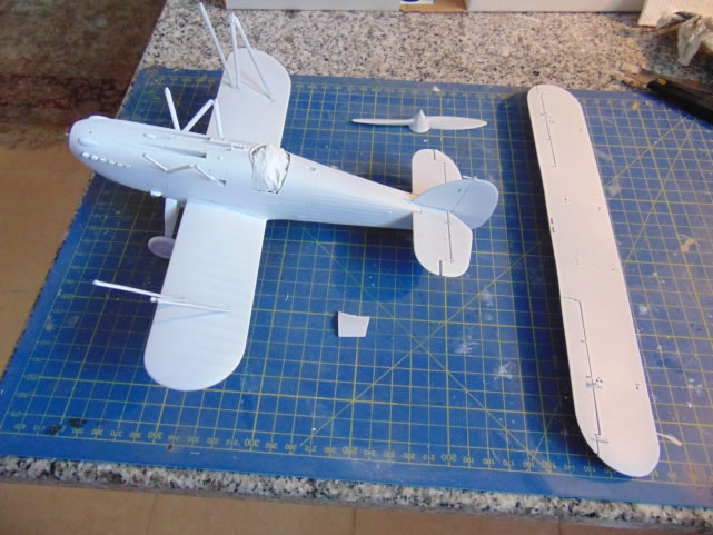
The model is now more-or-less complete and ready for painting. The only parts I left off were the propeller, wing aerials, venturi, pitot-static on the strut, machine gun barrels, telescope(?), cockpit door and windscreen.
Painting
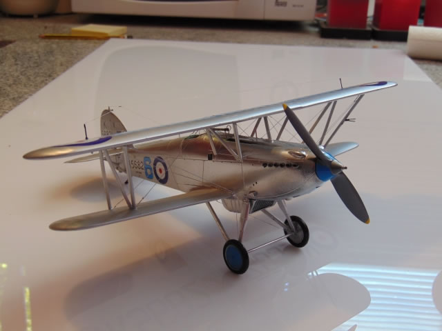
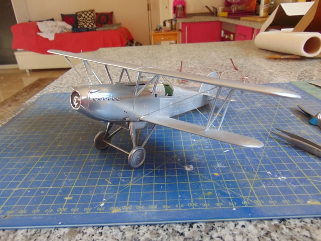
I decided that I would spray the underneath of the centre section and the top of the fuselage ahead of the cockpit in Alclad, then assemble the upper wing, rig it, and spray the entire beast with Alclad as one piece, rigging and all. This is to avoid the inevitable superglue traces on the Alclad finish and the rigging could be repainted later, if necessary. I used Tamiya white primer overall and checked for blemishes then masked the fabric parts and sprayed the metal areas with a high gloss mid-grey rattle-can. The result is the intended matt white underpainting for the fabric areas and glossy darker underpainting for the parts that should be highly reflective polished metal.
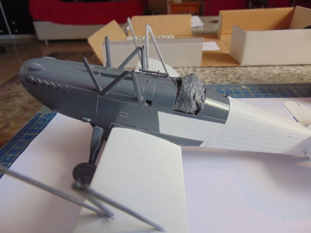
Then Alclad II Chrome was sprayed overall. I thought the finish over the fabric was a little uneven so airbrushed Aclad White Aluminium lightly, avoiding the polished parts. Incidentally, it is wise to check the compatibility of your primers with Alclad; lacquer and acrylic seem fine but enamel and Alclad don’t mix well, apparently. For the record, I used an Aztek A470 with a 0.4mm nozzle (turquoise).
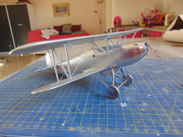
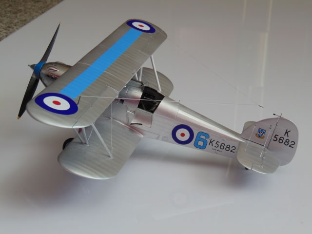
I was reminded that any surface blemish or defect (even fingerprints) is magnified a hundred times with these highly reflective Alclad paints, so be careful. Suffice to say that the finished result was exactly as I had hoped; if anything a little too shiny! I think it looks better then Bare Metal Foil and you get no problems with creasing. When you look at the photographs, remember that the whole aircraft was sprayed one colour, Alclad II Chrome, the difference in the final effect is simply due to the underpainting. Also, please remember that masking tape, even low-tack kabuki tape, damages Alclad highly reflective finishes. You can mask normal Alclad finishes, however.
Rigging
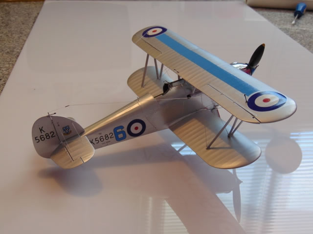
The Fury is actually a simple aircraft to rig; even so, I would have expected a rigging diagram in the instructions but there is none. For the record, there is no rigging between the interplane struts and simple sway bracing between the front and rear cabane struts and the fuselage, plus the flying and landing wires. The front flying wires are doubled but the rear ones are single. The landing wires go from the lower interplane struts and come together at the top of the rear cabane struts. There are turnbuckles at each end of every cable. There are rigging wires from the tailplane upper surface to the fin and control cables to the elevator and rudder. There is also cross bracing of the rear undercarriage struts but not the front ones.
The control cables are: rear fuselage: elevator up, elevator down, rudder. Fuselage ahead of cockpit: aileron cables to the upper wing centre section.
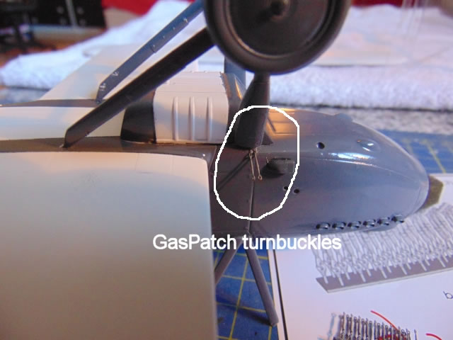
I decided to use GasPatch turnbuckles on this model; these were entirely new to me so this was a bit of an experiment in my quest tofind the perfect rigging accessories.
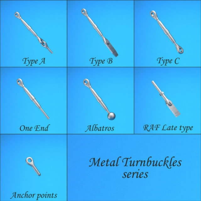
Their website is: http://www.gaspatchmodels.com. These turnbuckles are tiny, almost unbelievably realistic and are apparently produced by a sintering process and 3-D modelling. Looks like magic to me. I have to say that they are the simplest way of getting realistic rigging and I am truly impressed. You just drill the holes (0.5mm), remove the turnbuckle from its mounting block with tweezers, then glue it into the hole at the correct angle. A drop of superglue to secure it is all it takes. Couldn’t be easier. I also used the stretchy 0.2mm haberdashers rigging thread for the rigging and threading this through the larger holes (0.4mm?) in the turnbuckles was easy. The turnbuckles can be tweaked when rigged to align correctly.
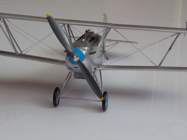
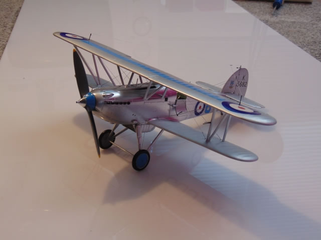
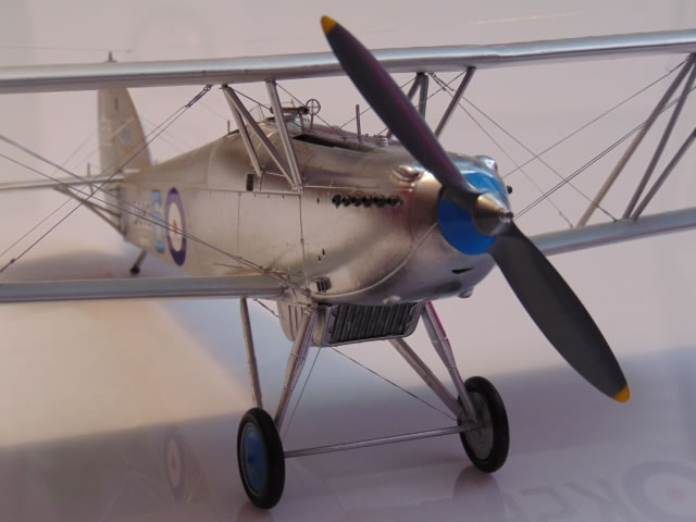
Of the remaining details, the gun ‘telescope’ (black) looks to be offset to the right but there should be a ring-and-bead sight, probably on the centerline (not provided). There are little aerial posts on the outer wings (I replaced them with brass rod) and just aft of the cockpit plus a mass balance/aerial attachment on the fin. A venturi is also provided for the port fuselage side which I left off until after painting. The coaming around the cockpit is black leather and the windscreen frame is silver. The propeller may be natural wood or black, I’m not sure; the colour instructions indicate brown but the Duxford Fury has it in black and I know that those guys do their research well. However, Guy Black, Technical Director of HAC who restored the Nimrod and Fury said (as reported in a Britmodeller forum): “The props are fabric covered and painted grey. The back of the blades is often matt black to avoid reflection. Tips are often yellow." That’s interesting and my best guess is that the props were originally black or natural wood but may have gone grey/black with yellow tips on the later trainers (the Fury trainer dates from 1938 when the type was obsolete) which would have been current practice. I checked contemporary trainers such as the Magister and Oxford and all had yellow prop tips (and were black…) I couldn’t find any colour pix from the 1930s, so we’ll probably never know for sure and props were changed frequently.
Another issue is the spinner colour. The colour scheme in the instructions shows a wood-coloured prop and rear spinner fairing, as if it was all one piece. The conical spinner front is polished aluminium but the rear part is also a fairing, not the wooden propeller hub. The wooden propeller sits inside it and I think that it would have been painted Cranwell blue, like the wheel hubs and upper wing strip. Also, it looks nice!
The decals were excellent with no need for any softener which is just as well as it does not mix with high shine Alclad. They slid off with minimum waiting and were easy to position. They were thick enough but not too thick and have a nice satin sheen which is perfect for the Cranwell aircraft but too shiny for the camouflaged versions. I added the guns and made a thin frame for the windscreen as the celluloid version provided looked a bit simplistic.
The final touches were to add the little bits that always get knocked off, the aerial posts, tailskid, venturi and rudder mass balance. Then the aerial wires and control cables to the elevator and rudder. All of a sudden it was finished.
I was very pleased with the finished Fury. It looks exactly right and, although I haven’t gone over it with a tape measure, I am certain that it is accurate. It’s not big, of course (span 283mm, 11.14 inches), but it’s substantial and passes the weight test in a way that plastic cannot. If I can quibble a bit, the radiator under the fuselage is very prominent and the grille would benefit from a photo-etched fret to do it justice. If there was a photo-etched fret then maybe it could also include a Sutton harness. That would increase the cost but I’d pay for it because radiator grilles are the kind of thing that photo-etch does well and there’s really no other way to get that fine grating-and-depth effect.
Many modellers are frightened of biplanes but this one slots together so easily that you feel you’re cheating; the rigging is easy as well. It’s even easier if you use Gas Patch’s turnbuckles which are really a revelation and the most perfect and trouble-free method of rigging a biplane that I have come across. The kit is well-designed and beautifully cast, really almost perfect. The decals are also perfect. It needs almost no filler. My main criticism is that the instructions are basic in the extreme and rely on the modeller doing enough research to remedy the situation, but that should not be necessary…in fact it is only this that would stop me recommending this as a first resin biplane. On a personal level, I’m happier with this model than in any other model I’ve made to date.
The finest model of the prettiest biplane ever. Go and get one while they are still available
Model, Images and Text
Copyright ©
2014 by Roger Hardy
Page Created 26 August, 2014
Last Updated
26 August, 2014
Back to HyperScale Main Page
|
 Home
| What's New | Features | Gallery | Reviews | Reference | Resource Guides | Forum |
Home
| What's New | Features | Gallery | Reviews | Reference | Resource Guides | Forum |