Modelsvit 1/48 scale
Curtiss XP-55 Ascender
by Andrew Garcia

Hobby Boss' 1/72 P-61A Black Widow is available online from Squadron.com
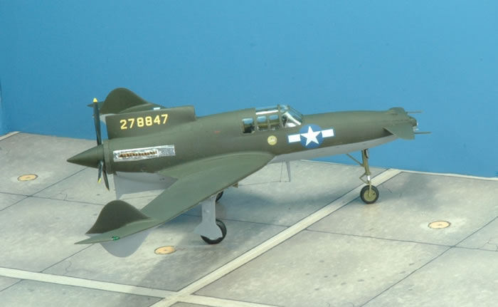
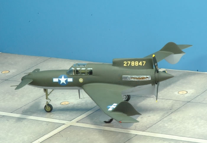
Modelsvit 48008 1/48 Curtiss XP-55 Ascender s/n 42-278847
Modelsvit is a Ukrainian based plastic model company which has released both 1/72nd as well as 1/48th scale products mainly of Russian designed airframes. There are a few 1/144 scale Russian submarines in their catalog as well. They appear to specialize in the production of Soviet warplanes and feel they are “establishing itself as a quality leader in the "short run" production technology” according to their distributors website. After building this kit, their Modelsvit 48008 1/48 Curtiss XP-55 Ascender product, I would not categorize it as a short run kit but consider it to be an outstanding state of the art injection molded plastic kit comparable to industry leaders in all regards. There is nothing “short run” about the model. This is a company to watch and actively buy their kits for some modeling satisfaction.
In January 2019, I saw a beautiful built model of the Modelsvit XP-55 in 1/48th scale posted by Darren Roberts in one of the Hyperscale forums. The kit was from a company I was not familiar with called Modelsvit. I was impressed with his build and he confirmed it was a very enjoyable kit to build. After finding and reviewing the contents of the Modelsvit website I was pleased with the 3D CAD renderings of the Modelsvit 48008 1/48 Curtiss XP-55 Ascender kit and was inclined to get a copy of the XP-55 kit. But, many of us have seen nice 3D CAD drawings only to find the final product lacking in some way such as fit or odd renderings of components. I must admit I was impressed with the thoroughness of their airframe details since I had spent some time reading up on the XP-55 when I built the Czech Model XP-55 a few years ago. I had not heard of Modelsvit and it was a shock to find this level of state of the art product development without seeing any previous comments on our forums about them. They could be there, I just didn’t recall seeing them.
The next challenge was getting the kit. I did a web search for sources of Modelsvit products, which at that time resulted in finding their company website which does or did have a direct product purchase capability and Hannants in the U.K. selling the product as well. I acquired the kit from Hannants and was very surprised upon opening the box to find a well molded and beautifully complete package from Modelsvit. Although the company refers to itself on its Facebook page as a limited run model company, there was nothing “limited” in their XP-55 kit. Maybe the future has finally caught up with the former limited run manufacturers? Mainstream producers should take note of how to accurately design and produce model kits using Modelsvit as a guide! Fundamentally, it really looks like they did an actual visit to the XP-55 on display at the Air Museum and studied the actual XP-55 airframe as the project starting point rather than using someone’s scale drawings as the guide for product development and 3D CAD renderings used in making this kit.
To give you some background on the XP-55 and additional model airframe detailing in September of 2014 Hyperscale featured my completed Czech Model Kit No. 4806 - Curtiss XP-55 Ascender. Brett kindly posted my build review of the Czech Model Kit No. 4806 - Curtiss XP-55 Ascender where more airframe information can be found on the airframe and its unique features.
http://www.hyperscale.com/2014/features/xp5548ag_1.htm
The Modelsvit kit is comprised of 144 parts in grey injection molded plastic on six trees; seven clear parts; 26 photo-etched metal parts; extensive stencil and cockpit decals with markings for two aircraft. An excellent eight page instruction booklet is clearly illustrated with a color four-view painting guide. There are 29 steps in the assembly process. I was delighted to find finely engraved details, excellent overall molding quality, minimal flash and the comprehensive assembly instruction booklet. Others have commented on finding some slight flash but I did not perceive any flash of note on the injection molded parts.
I was impressed by the superb level of excellence in this release, crisp surface detail, and accurate dimensions. Instead of using locating pins and sockets many large components have “guides” or ridges inside to provide alignment but also have the ability to accommodate slight movement to get parts alignment eliminating seams. The moldings are outstanding and that’s not just in the box but also in the true test when you put the parts together. The kit features petit scribing, accurately molded highly detailed parts, etched metal parts complementing the plastic rather than unnecessarily replacing plastic components and a low parts count. Most parts fit tightly with only a few minor areas requiring a small amount of putty or your favorite gap filler. The entire wing root to fuselage join, main fuselage, wings, had zero, as in none, gap problems. Both sides just snapped into place without filler with a touch of Tamiya liquid glue used. Nose and main wheel wells are accurately detailed. It is apparent that a great deal of intelligence was applied to the kit in terms of keeping the parts count low for such a high level of model detailing on a complex compound curvature airframe. All the items that were missing or poorly detailed in the Czech Model kit that I listed in my HyperScale build review in 2014, have been faithfully rendered in this model.
Even the nose tip light is perfectly formed on the clear parts tree with the final assembled component part G5 inserted into part F9 fitting precisely after sanding the sprue attachment nib with a tri-stick sanding device. The prominent nose light did not require an aftermarket fix as did the Czech Model kit where I used an M.V. Products light lens.
The cockpit is a small model unto itself. Everyone who sees it is astonished since it is comparable to the best resin cockpits without any fiddly or difficult assembly of components. It all fits together! The cockpit tub goes into the fuselage halves without any gaps or fitting concerns. It’s not just that the parts are there but that they are exquisitely molded with perfect detail. I never noticed a shortcut in detailing which is the way it should always be. The instrument panel, part E12, by itself is very basic, just a flat plastic part with no details other than recessed locations for the dials. I would have preferred accurate raised detailing for the styrene instrument panel part E12. I have found using a well detailed plastic panel with an accurate high-definition decal provides nice results. But, they do provide two options for the instrument panels and either alternative looks very nice.
You get excellent choices in alternative building options such as open or closed canopy clear parts. There are two choices of cockpit interior instrument panel construction either using etched metal that you paint or well printed decals for the cockpit instruments and stencil details for the styrene option. There are many fine details rendered on the decals for items such as stencils like “Map Case” decals # 47 & 48 and the “Main Junction Box” decal # 44 that is behind the pilot. Parts are provided to select an open nose wheel bay or closed nose wheel bay which is how the airframe normally appears. The nose wheel bay is left open only for maintenance access. The wing tip navigation and formation lights are part of the transparent parts tree, sprue G, providing an enhanced appearance and they fit perfectly too! By providing the paint masks for this kit Modelsvit did everyone a favor and enhanced the end satisfaction of all modelers. Since the units produced of this XP-55 kit may be lower than say some of the more significant WWII airframes like the Spitfire, 109 and P-51’s by other manufacturers with robust sales & distribution, the chances of a paint mask supplier like Eduard opting to provide this paint mask in their catalog is low. The amount of greenhouse window panes is high so masks are needed. I am still waiting for paint masks for some of the Japanese subjects with similar greenhouse window treatments to appear in Eduard paint masks for example. You can always use your favorite mask material but I do like pre-cut masks for multi-panel glass canopies.
Could or should anything be changed with this kit? I am very satisfied with the kit in all regards. It was a delight to build and is a fast and easy build too. A few suggestions for Modelsvit is more along the lines of future improvements that are constructive changes in their approach to a few areas. I would like to see them consider using a different propeller attachment approach. It could be improved by adopting something similar what Hasegawa and Tamiya, for example, have adopted – using a small captured vinyl cap inside the airframe into which the prop shaft can be securely inserted or added after construction and painting steps are finished. That approach I have found results in a secure prop that can rotate, be removed for transit and permit easier painting and assembly. I had some trouble with prop assembly step 18 requiring dry fitting and round filing of the shaft hole in parts F15, F16 and F19 for the shaft to pass through and rotate. It is a cumbersome multi-part solution for a prop shaft placement compared to the vinyl cap approach. It made it more difficult to mask the prop for painting as well.
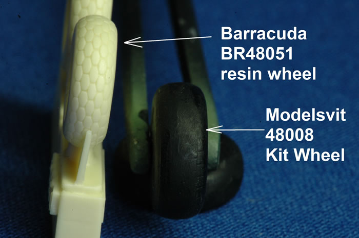
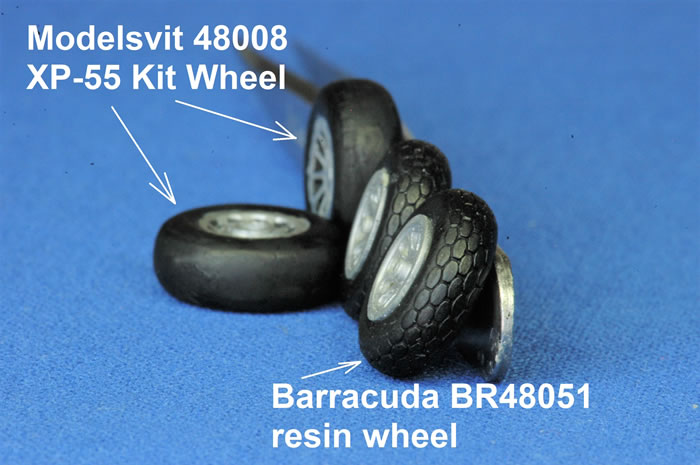
The main wheel assembly could be improved by separating the plastic (on a real airframe it is rubber) tire from the (on the actual airframe it’s metal) rim. Molding the tire in one piece with a separate rim would be my preference. The XP-55 has a very visible block tread. Modelsvit molds the wheel in two parts (parts C9 & C10) cutting it in half (see steps #11 and #12 in the assembly instructions). During assembly the two halves are joined but I had a significant gap in the center requiring filler and sanding eliminating the nicely molded plastic block tread detail of parts C9 & C10. I was not happy with the final appearance after a lot of unnecessary effort on the main wheels and chose to replace the kit parts with resin tires which had the improved tread appearance as well as ease of painting. Another area that could be better is I would look forward to some good aftermarket supplier making the exhaust stacks in resin with hollow ends. The kit plastic is fine but I think there are some resin aftermarket exhausts, some versions for the P-39 for example, that could be used for this airframe offering hollow end tips and welding beads on the seams. I used the kit parts since this was not a major concern and they do look fine. I have seen some others hollow out the kit plastic exhaust tips for a better appearance. IN a perfect world Rexx metal exhausts would be available.
The build of the Modelsvit 48008 XP-55 Ascender was fast and very pleasant at all steps of the process. I followed the kit instructions leading to a complete cockpit tub by assembly step 8. I spray painted most parts with Gunze H58 interior green. It was the finest injection molded plastic cockpit I have ever built. After gaining experience building the XP-55 cockpit during my Czech Model kit build I was prepared with an understanding of how the XP-55 cockpit actually looks. There are some excellent close up interior photos of the cockpit area taken during the Air Zoo restoration that help with this area. Honestly, I was really impressed with the cockpit components Modelsvit has provided in injection molded plastic. They look fantastic on the sprue and even better once assembled! They all fit and none were difficult to paint or assemble. Unlike some experiences of assembling a kit where you wonder if the designer or assembly instruction author has actually built the kit, because the parts just don’t fit or your eyesight and dexterity, though good, just can’t do what they are alluding to in the assembly instructions (because it’s not humanly possible and they know it) this one worked. The Modelsvit 48008 XP-55 Ascender was outstanding in all regards. I tip my hat to them recognizing their accomplishment!
The kit building instructions lists paint colors using the Humbrol paint line in addition to pigment color names in both English and Ukrainian. I used the Gunze “H” Aqueous paints and Tamiya acrylics in building this model. I used Tamiya Extra Thin Cement # 87038 as the bonding agent. It worked flawlessly. Some parts, such as etched to plastic bonds were glued using cyanoacrylate gap filling glue as well. Most of my gap filling was done using Evergreen #9010 .010” / 0.25mm sheet styrene as a gap filler rather than putty.
You have a choice of two approaches to the kit instrument panel. A traditional plastic instrument panel with very well printed instrument decal results in a beautiful instrument panel. I would have preferred to see more three dimensional molding on the styrene plastic instrument panel. I chose to use the etched metal version and apply the decal on top of the etched metal with some Micro Sol to get improved raised details rather than placing it underneath the etched as the instructions would suggest. This was just my personal preference rather than any error or wrong approach by Modelsvit. The Modelsvit etched was easy to work with and definitely added some nice details to the cockpit area. But, the injection molded plastic for the rest of the cockpit area is the real surprise. It was fantastic! For example, the engine controls throttle and mixture levers were styrene and easy to paint and apply. The kit was designed to use them rather than the sometimes unfortunate experience of removing some kit plastic content only to find the etched doesn’t quite fit or the etched metal use results in a flat looking 2D replacement for a 3D component. The seat assembly mirrors the actual seat components even including a detailed seat belt anchor point or attachment point behind the seat!
The instrument panel decal conformed to the kit etched metal and with some Micro Sol applied followed by drops of Future gloss on the individual dials I had the look I prefer. I was satisfied and very pleased with the resulting fine looking instrument panel. Their instrument panel decal was nice with white dials on a black background but lacked color. The actual cockpit instruments have a good amount of red in the dials when compared to a color reference photo found on the web.
One of my deviations from the OOB kit approach was to use the Eduard 49082 Seatbelts USAAF WWII in lieu of the kit etched metal belts. The Eduard 49082 Seatbelts are the super fabric versions and not etched metal. They are easily folded and take on a more natural drape or contour than most etched metal belts. The kit etched were correct in size and had excellent definition and details. I did paint them and fold the silver metallic buckles onto the painted surfaces so I can confirm you will get very nice results using them. I just liked the Eduard belts for their finer color painting which provides much better detailing than I would get with my own hand brush applied painting of these components especially for the black center stitching which is prominent in close up photos. The lap restraint has two material components, using canvas for the main belt with a smaller sized leather strap under the lap buckles. The Eduard color etched makes a fine representation of the canvas including the stitching which was the main reason I used them. They include the leather accessory portion so I went that route instead. I did run into a problem using them though. When I applied the Tamiya panel wash to the seat some of the wash overran onto the painted the belts and ruined the look I had sought by discoloring the belts and over-enhancing the textured finish of the rubberized material causing an out of scale texture effect. Using etched metal belts would have avoided this problem since the wash on etched belts doesn’t have the textured material indentations to flow into.
Before starting construction I read the kit instructions and placed notes on areas where I wanted to enhance existing kit details or consider alternative building approaches. The kit is outstanding OOB, nothing missing or requiring replacement. It has everything you need. I did use some resin replacement wheels from Barracuda, the BR48051 P-51 Mustang to get a textured hexagonal tread. A friend who visited the XP-55 Air Museum display found two types of tire treads in use on the main wheels of the XP-55 which he was going to incorporate into his XP-55 model build so super-detailers should be aware of this option. Period photos in references showed the same type of tires, no mismatched tire treads in use, so I used the Barracuda resin wheels because they have outstanding detail. Barracuda’s attention to detail with features like including the valve stems and providing separate hubs for ease of painting is appreciated. For comparison purposes I did assemble and paint the kit plastic wheels (steps 11 & 12). I did find it difficult to hand paint the kit tires because the wheel hub rim juncture with the tire is too close so you will want to use the kit paint masks if you use kit styrene wheels. From an accuracy perspective the kit plastic would be correct in having such a shallow rim contact lip on the tires.
The museum XP-55 only has the yellow propeller dimensions specification stencil on the propellers. I wanted to also include the round Curtiss logo on the propellers so I did by using the Fundekals prop logo for the Curtiss Electric propeller along with the kit stencil. This decal is OOP but I am told a replacement including more than just the previous three versions of prop logo is in the works.
Parts fit is precise and very nicely detailed for the major components. Assembly steps 1 to 8 build up the cockpit and nose wheel bay. My only suggestion is to pre-paint most of the sprues green zinc chromate before cutting them from the sprue and maybe adding a few drops of black to get the Curtiss interior green look. Just don’t forget to add the many stencils to the cockpit area during final cockpit assembly since there are quite a few and the results are stunning. Modelsvit did an excellent job researching and provide a completely detailed stencil package for this area. I used a Tamiya # 7131 panel line accent color on the cockpit plastic as a wash.
Step 15 is the assembly of the dorsal intake duct. I remember this step well from the Czech Model kit where I was initially not sure how to proceed due to unclear instructions. The Modelsvit kit step # 15 was clearly diagramed and included is an in scale use of photo etch which went into a grooved cavity inside the intake duct – a very nice attention to detail and ease of assembly. In step 16, I inserted this part, the cockpit tub and front landing gear well and strut along with some lead weight in the nose.
Steps 16, 17 and 21 again impresses you with the close fitting parts assembly. I did not use any filler on the fuselage join, wing attachment to the fuselage areas which is highly unusual for a short run kit. It was a delightful and most pleasant experience.
The next steps were easy but I found the underside engine cooling intake in assembly steps 19 & 20, a multi-part assembly, to add an area that was one of the few that required a small amount of putty or styrene strips & sheet material to clean up small gaps between this part and the fuselage. After building this section assembly I had the impression some aftermarket supplier could make a big contribution by casting a one piece intake section replacing the assembly steps 19 & 20. By having it in one resin casting as a drop fit part it would speed assembly, reduce gap filling and sanding time. I would recommend having this section as one resin part which would still utilize the kit plastic part F6, which is the rear component with the radiator faces, as an improvement. That would allow painting the screen area, part F5, flat black with some silver dry brushing of the screen section. You could paint the resin intake trunk area zinc chromate green then joint the two parts and attach them in step 22. Since we all know we must build with what we have I used the kit parts and all went well in the end. Before attaching the final component from assembly steps 19, 20 and attachment step 22 check for fit to the fuselage. I had a small gap which would be very difficult to sand or file. I used the final assembly seen in step # 22 as a template to create a gasket from Evergreen #9010 .010” / 0.25mm sheet styrene as a gap filler rather than using putty. Once the component was attached I slipped in the “gasket”, applied some Tamiya Extra Thin Cement # 87038 which eliminated the small gap in a very difficult to sand area between the fuselage and scoop.
The XP-55 kit does not have a gunsight. That was intentionally not with the kit since the three airframes never included that component. Since the XP-55 sn 278847, the third prototype which is the one that I am building did carry armament, I decided to add the Quickboost # 48014 K-14 American Gunsight to the kit. I like how it looks and assumed since the guns were there in the third prototype, eventually they would have added this gunsight had it not crashed. Unfortunately, the airframe of sn 278847 was destroyed in an airshow accident when the plane crashed during an acrobatic maneuver before gun testing commenced. The third prototype XP-55, sn 42-78847 airframe was lost on May 27, 1945, during the closing day of the Seventh War Bond Air Show at the Army Air Forces Fair at Wright Field in Dayton, Ohio. After a low pass in formation with a Lockheed P-38J Lightning and a North American P-51D Mustang on each wing, its pilot, William C. Glasgow, attempted a slow roll, but lost altitude and crashed, sending flaming debris into occupied civilian ground vehicles on a highway near the airfield. The crash killed Glasgow and four civilians on the ground.
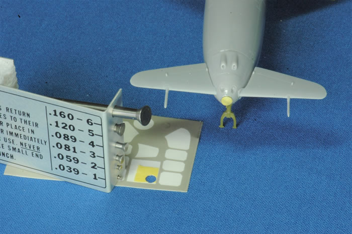
Step 21 has the wings, canard and nose tip added. If you want to have a really nice nose tip light I recommend working with part F9 by punching out some shiny material inserting it and securing it inside just behind the clear plastic lens part G5. To mask the clear lens interior shiny part I used a Waldron punch bit number #6 (.160 inch) diameter with some Frogtape which is similar to the kabuki rice paper masking material. I cut a small square of tape, placed it on an open area on the masking sheet and punched out a perfect front nose landing light mask. I tried using the kit supplied mask but it looked undersized and this area is very prominent so I went with my own approach and it worked well. I also used the Waldron punch for the shiny reflector cut from the snack bag as well. I masked the Modelsvit kit light by using a punched disk from Frogtape rather than the kit mask. I placed and secured the highly reflective disk behind the clear part in assembly step 21 and moved on with the kit assembly. I created a mask using Frogtape (FrogTape Delicate Surface Painting Tape, 1.41 in. x 60 yd. Roll, Yellow (280221)) which is a masking tape found in the paint department of hardware stores which claims to be for delicate surfaces. It is similar to the material used in Eduard masks. Since this was my first time use of the Modelsvit masking material I did not want to risk ruining the beautiful and prominent nose tip landing light by using the kit mask so I made my own. The photo below shows the nose light mask creation step. The kit mask is your alternative because it is provided in the kit mask sheet and should work.
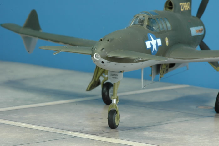
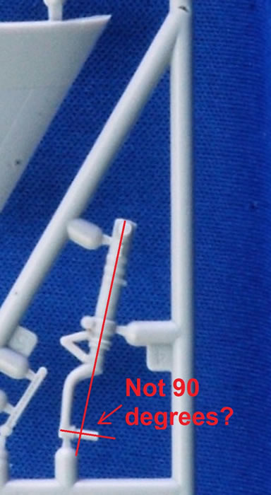
Step 26 has the main landing gear and linkages assembled and glued into the wheel wells. It is an easy step and here’s not much to perform. On the “C” sprue I noticed the main landing gear parts C4 and C11 had axels which appeared slightly off alignment. I dismissed this initial observation thinking it would work itself out when the wheels were attached. The assembly worked well but when I added the wheels to the axel the final look when viewed from the front was poor. The wheels had a “toe-in” look meaning they were not contacting the surface at a 90 degree angle to the ground because perhaps the axel was in fact slightly bent upwards. It was not because the kit part was twisted or warped, a replacement kit part would not fix this. It isn’t caused by the model being too heavy for the landing gear. This is just my opinion and the real underlying problem could be I attached the main gear to the wing at the wrong angle causing a cascading effect of misalignment showing up as improperly aligned wheels as they contact the ground. The kit attachment point for the main gear is not very secure in fitting. Because of this concern of a future accident separating the gear leg from the attachment socket, I did drill and glue a piece of wire into the landing gear leg and into the wheel well. I used the wire to secure the leg to the attachment spot in the wheel well. Using gap-filling cyanoacrylic glue I aligned the main gear leg without the wheel attached. Once I attached the wheel I was disappointed in its appearance.
Perhaps it might indicate a potential permanent problem for all builders but that is my speculation. At this time I would strongly suggest you consider replacement with an aftermarket main landing gear leg such as those from the Scale Aircraft Conversions product line, which provides white metal replacement landing gear that can be easily reshaped to get the 90 degree angle. This is highly recommended but again it could just be my introducing an error during my assembly approach. I wrote to Scale Aircraft Conversions requesting this landing gear be added to their product portfolio because it may be a flaw in the kit part that is not fixable with a replacement plastic part. Changing the stance of the main gear to accommodate the axel alignment would make the entire assembly look wrong. The assembly, once you finish step# 27, has many parts and it is not a simple fix changing the stance of the main gear leg. Again, this is just my observation and I could definitely be wrong but be forewarned if I am correct in my observation. You might avoid the rework I am going through.
Step 27 is where I had some additional difficulty with the build. In this step you attach the main landing gear doors, along with some photo-etch parts. Although the instructions on page 7 appear clear, it was a challenge overall and some parts like the attachment of a tiny photo etch part # Z11 or # Z14 representing very small door hydraulic piston linkages on the landing gear doors just did not click fit into place as did the rest of parts in the assembly steps before this area of construction and assembly. Everything turned out acceptable in the end but this step was full of delays and uncertainties. However, I can say the area is highly detailed and part of it is through the use of etched metal components which gives very precise detailing. Despite good assembly instructions and clear drawings I caution you when you go through this step to be careful and deliberate with your work just because of the complexity of multiple parts in an awkward assembly area.
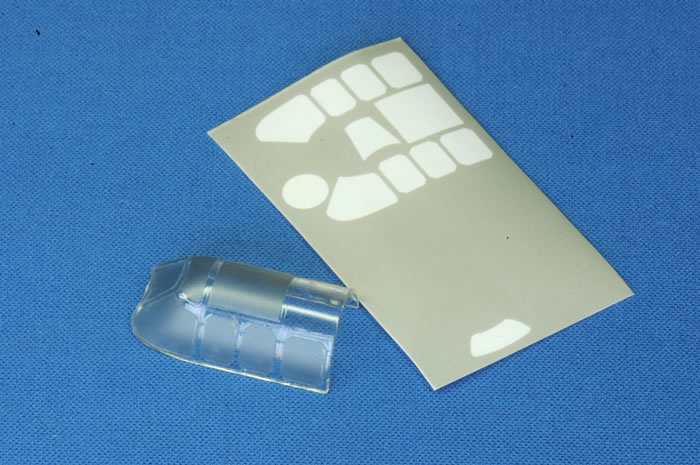
Modelsvit provides very thin smoke tinted plastic masks for both the inside and outside canopy framing. Although I have developed a preference to use Eduard canopy masks because they are relatively thick and easy to apply or remove, at the time of this build there were none for this kit from Eduard. Many years ago Eduard started their paint mask product line using a thick dark flexible plastic sheet material. The adhesive was not strong and often failed. Sometimes the masks fell off and they did not stay attached to compound curves or anything other than a flat surface very well. Eduard fixed this by using the rice paper or kabuki masking material which works very well and is the raw component in their current products mask materials. When I first saw the Modelsvit masks I had a passing thought that maybe this was going back to the technology used with Eduard’s initial masking products. But, no they worked very well and you can use the kit masks with confidence. I liked them very much and they work perfectly.
At this point in the build the end is near and you only have masking, painting and decaling to finish before you are looking at a beautiful model. No panel wash was added to the final finishing steps since it was a pristine condition experimental airframe taken to an airshow. The clear coat was Future floor wax followed by a final Testors # 1160 Dullcote Lacquer coat. Small bits like adding the wingtip formation lights, under fuselage antenna mast part A2, pitot part A4, and some bare metal foil to the engine exhaust area ends the project. I usually build my models with open cockpit to permit viewing the interior. Since I already had a finished Czech Model open cockpit XP-55 on the shelf I built the Modelsvit version s/n 42-278847 with a closed cockpit canopy. The decals are excellent. After they were applied they conformed to every panel line or curve without my using any setting solution. I was impressed – nice decals!
I encourage you to get one of these kits and build it. It is a fast build with few frustrations leading to a quick and very enjoyable build. I was building it so quickly I forgot to take pictures of the final finished cockpit. When it fit perfectly into the fuselage I quickly glued the fuselage parts together and kept building. Your finished model will look very nice too! It definitely has obsoleted the Czech Models XP-55 kit. Modelsvit has a high quality complete package and I hope to see and buy many more kits from this company if they maintain this level of product quality! They have indicated on Facebook that their next 1/48th scale kit will be of the P-51H Mustang. Kudos to Modelsvit.
References
-
American Secret Pusher Fighters of World War II by Gerald H. Balzer Specialty Press 2008 (XP-55 section - pages 62 – 103)
-
Curtiss Ascender XP-55 by Gerry Balzer 2014 (Ginter Books # 217 - Air Force Legends series)
Note: There is one remaining airframe of the Curtiss XP-55 Ascender, serial number 278846, which was restored by The Air Zoo. The Air Zoo is a museum located at 6151 Portage Road in Portage, MI, halfway between Detroit and Chicago, USA. The Air Zoo received the XP-55 Ascender on loan from the Smithsonian National Air & Space Museum in exchange for a restoration. At the time of this review, April 2019, the XP-55 remains on display at the Air Zoo.
Text and Images Copyright © 2019 by Andrew Garcia
Page Created 10 July, 2019
Last updated
10 July, 2019
Back to HyperScale Main Page
Back to Reviews Page

|
 Home
| What's New |
Features |
Gallery |
Reviews |
Reference |
Forum |
Search
Home
| What's New |
Features |
Gallery |
Reviews |
Reference |
Forum |
Search