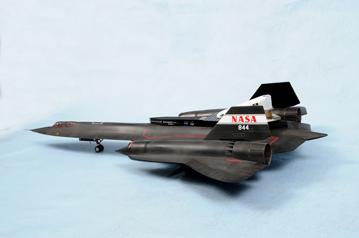
Testors 1/48 scale
SR-71 LASRE
by Chris Derks

The SR-71 LASRE Experiment |
“The Linear Aerospike SR-71 Experiment (LASRE) was a propulsion flight experiment for advanced space vehicles such as the X-33 and reusable launch vehicle. A linear aerospike rocket engine was integrated into a semi-span of an X-33-like lifting body shape (model), and carried on top of an SR-71 aircraft at NASA Dryden Flight Research Center. Because no flight data existed for aerospike nozzles, the primary objective of the LASRE flight experiment was to evaluate flight effects on the engine performance over a range of altitudes and Mach numbers.”
Excerpt from: Kimberly A. Ennix , Griffin P. Corpening , Michele Jarvis , Harry R. Chiles, ‘Evaluation of the Linear Aerospike SR-71 Experiment (LASRE) Oxygen Sensor (1999)’.”
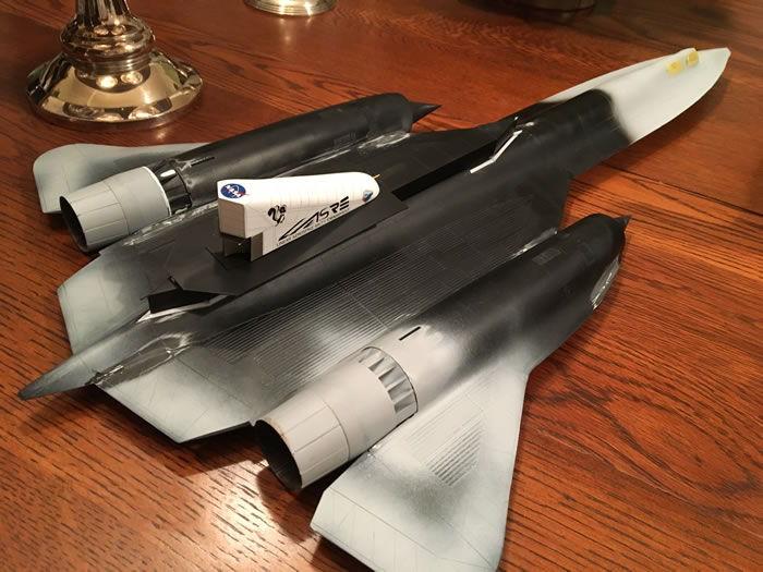
Two years ago I purchased Tony Landis’ “Lockheed Blackbird Family Photo Scapbook” with hopes to build one of the YF-12s using the long out of production 1/48 Testors kit. I was immediately intrigued by the cover photograph which had a NASA SR-71 carrying a strange wedge mounted on a long “canoe” riding on the back of the jet. I did some internet research and changed my mind to build the 1/48 Testors SR-71 with the LASRE riding on its spine. The only way to go about building this project was to scratch-build anything that wasn’t part of the jet along with getting custom decals for the LASRE system, as well as the NASA logo on the jet’s tails.
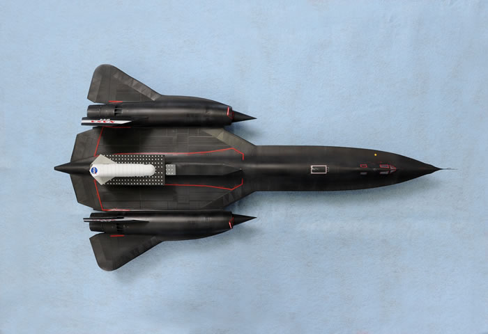
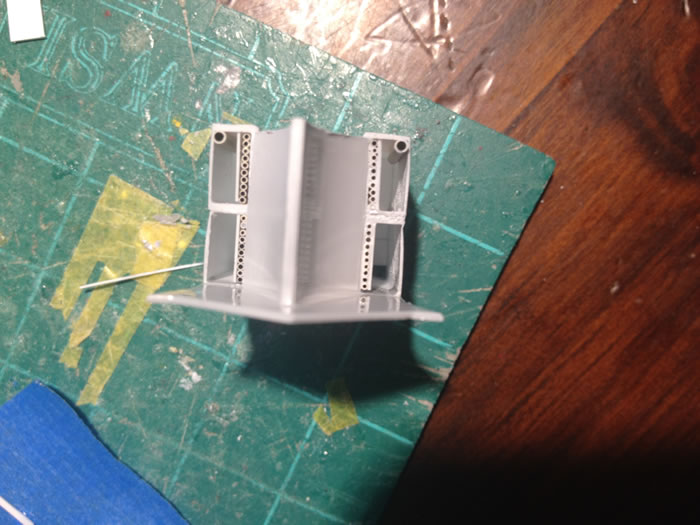
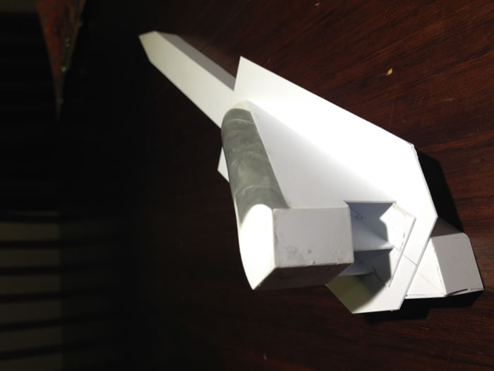
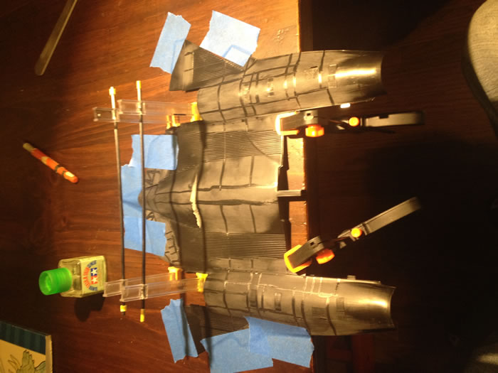
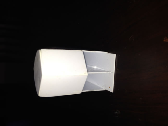
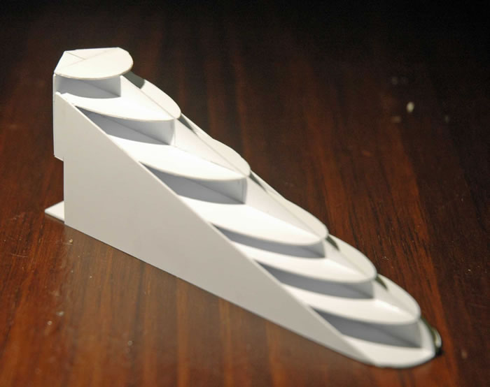
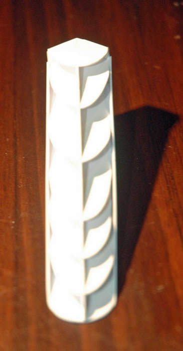
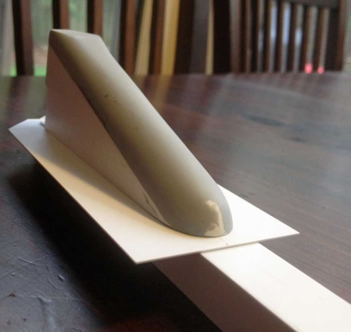
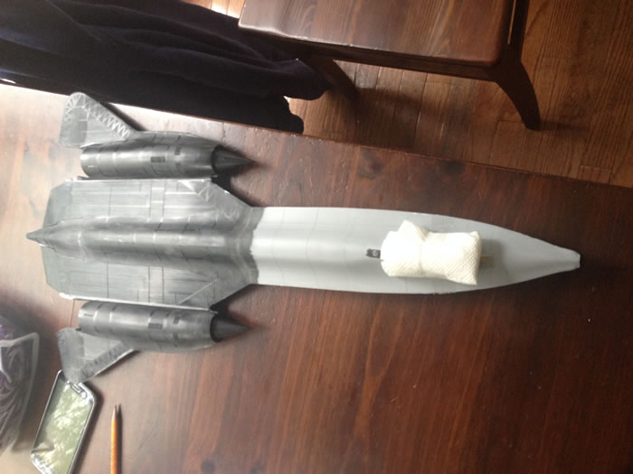
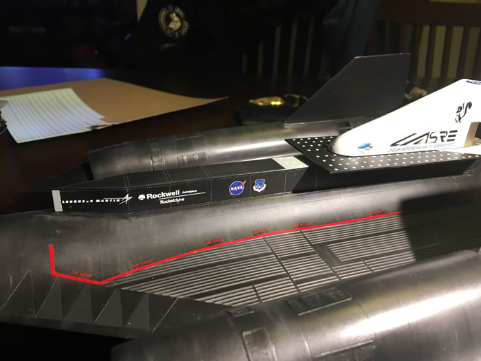
Before I would even consider building the jet, I needed to see if my skills were up to the challenge of creating something out of nothing. I was fortunate to find in my on-line searching some schematics, which had the actual dimensions of the LASRE pod. If that wasn’t enough help, I also found diagrams with the LASRE broken down into cross-sections. I took the schematics and blew them up to 1/48. Using the cross-sections as a template I cut out the sections using .015” styrene. Once the “skeleton” was finished I filled the gaps with Miliput and Apoxie Sculpt, and then sanded to shape. The business end of the LASRE took a little bit of guesswork to get right. After some trial and error I ended up with a convincing aerospike section. One of the issues I had with this part of the build was that the aft end of the motor changed its configuration from time to time. I then built the first of two “canoe” sections. The first one was mostly a proof of concept attempt to see how it would fit on the spine of the model. This ended up being the greatest challenge of the build. The spine of the jet narrows and tapers as it moves to the rear. This required a lot of sanding by placing sand papers on the spine and passing the model over it several times to get it to conform to the model. My success was not 100%. I still had a few gaps where the canoe did not want to mate with the model. I filled those gaps with Miliput and ran strip styrene around the entire perimeter of the canoe (like on the real thing). To finish this part of the build, I used Archer rivet decals. The effect was a pleasant surprise.
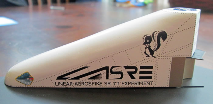
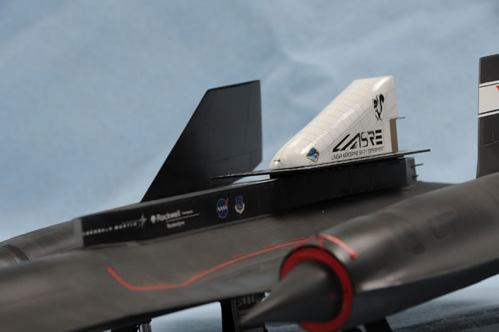
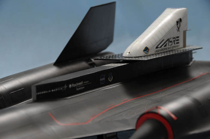
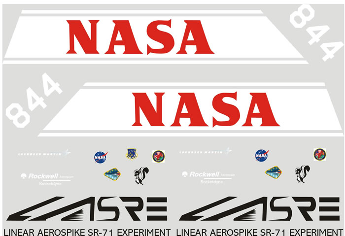
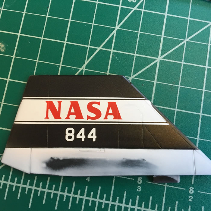
An interesting challenge was to come up with markings that adorned the LASRE and canoe. It was safe to say that none existed except for the NASA “meatball” logo. I was able to get suitable .bmp and .gif files for the Lockheed Martin, Rocketdyne, Phillips Laboratory, Skunkworks, and the two LASRE logos. I contacted Red Pegasus Decals to handle the custom decals that were used on the LASRE. The second round of custom markings came from Paul Metz who made fantastic masks for the NASA fin flashes on each vertical stabilizer. General markings for the SR-71 came from an Afterburner decal sheet. Rivet decals on the LASRE, canoe, and jet were from Mike Grant Decals.
A lot has been said about the Testors SR-71 kit over the years. Shortcomings of the kit are the lack of cockpit detail, shallow wheel wells, landing gear that are split in half, and the raised panel lines. Definitely not in the category of current molding technologies with regards to engineering, detail, and fit.
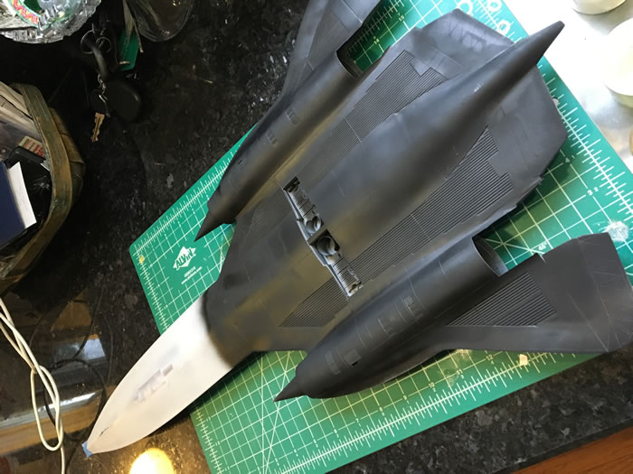
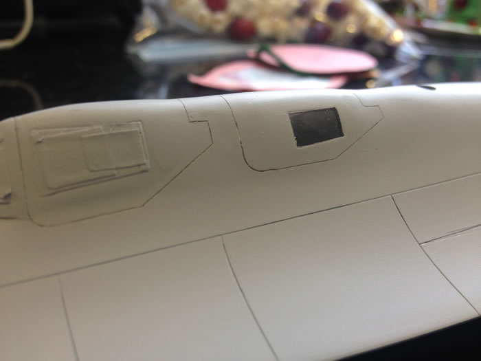
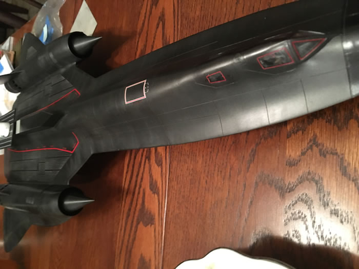
I started the build with re-scribing the entire model. It was generally pretty easy to do due to most of the surfaces being relatively flat and free of curved lines. Unfortunately, there are seams that run through the leading edge “pie slices” on the underside of the model. I have had terrible luck scribing across and through putty. I chose to use the liquid styrene method to fill these seams, which allowed me to scribe through them without any issues. I made my liquid styrene putty by mixing the black sprue from the kit with Tamiya super-thin glue. The dissolved styrene needs to be applied in thin coats and given enough time for the solvents in the glue to evaporate out of the model. I used this material later on in the build when it came to fairing in the “boat tail” section with trailing edges of the fuselage. I had very bad fit around the exhaust blow-in door section, which took several applications.
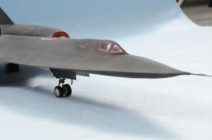
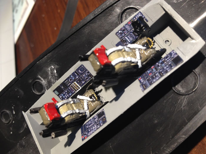
I previously decided to close the canopies because I felt that having them open would kill the lines of the jet.
This freed me up to skip a lot of the detailing that I would do on other projects. I used some Airscale decals and bits from old Eduard color-etch sets. I did use two True Details ejection seats as they would be seen through the windows.
Construction was very straight forward. I decided to glue parts for the upper fuselage together, which included the center section and the upper half of each engine nacelle. The instructions suggest that each nacelle be previously assembled and then attached to the completed fuselage. I foresaw alignment issues if I went this route. This did result in the aforementioned parts fit in some places as well as knocking the left nacelle out of round. Once the model was assembled, I let it sit for a few months to allow the glue and liquid styrene to cure and harden.
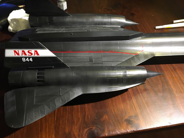
While the model was drying, I used the custom masks to paint the NASA fin flashes on each vertical stabilizer. During this step, I was experimenting with different variations of black to paint the model. I tried several formulas, but settled on the lacquer-based Gunze “metallic black” for the overall color that I would paint the model.
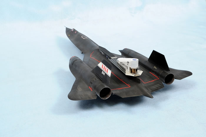
Building and Attaching the Canoe |
Construction of the canoe was relatively simple. Several styrene cross-members were glued inside to give the part more rigidity. I added two sections of nickel tubing from Albion Alloys to represent purge lines located at the rear end of the canoe. The next item to build was the “table” that the LASRE was mounted to. It was nothing more than measuring out its dimensions on sheet styrene and cutting out. The table does not sit flat on the canoe. There is a beam that runs down the table, which then is attached to the canoe. I replicated this with a semi-robust strip of styrene. The table and completed LASRE were measured and locating/mounting pins and holes were made to add some strength and keep things straight when it came time to mount the LASRE at the end of the build.
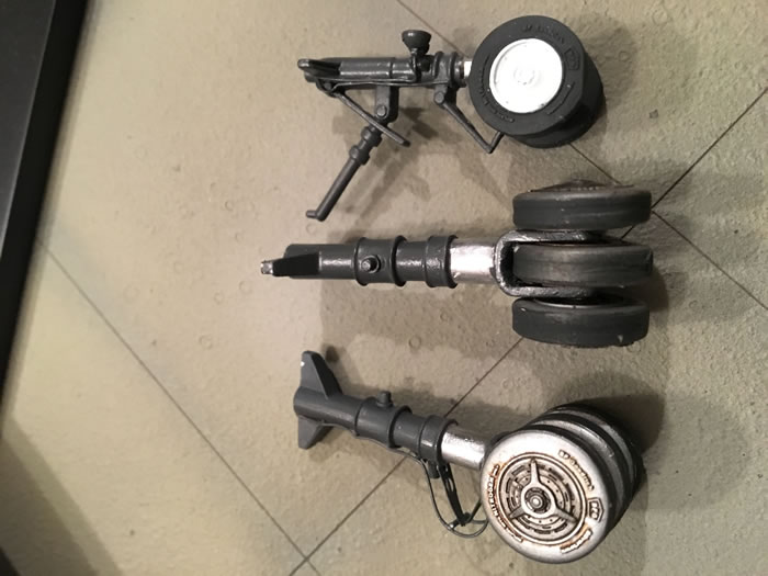
The kit landing gear and wheels are essentially useless. I replaced them with SAC gear, and excellent wheels from Fisher Model and Pattern. These modifications are an essential to this build for their strength and detail.
The wheels were painted with Alclad metalizers. The tires were given aluminum colored sidewalls with a mix of Tamiya NATO black an aluminum to show wear.
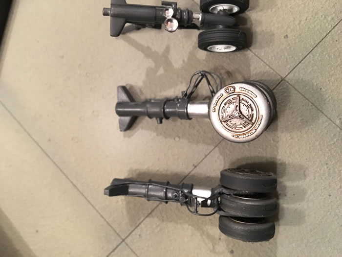
The SAC gear struts were detailed with lead wire for brake-lines, strip/rod styrene, and aftermarket landing lights. The gear was painted with Tamiya RLM-66.
Kit exhausts lack in detail, so I used replacement parts from Cutting Edge. The Cutting Edge parts replace kit parts 29, 30, 31 (for the left side), and 37 (for the right side). The Cutting Edge part that replaces kit parts 31 and 37 absolutely refused to fit the Testors parts. The kit nacelle parts were not completely round like the Cutting Edge parts were. Some of the detailed vanes were not completely cast and proved difficult to fix, so I threw them out. I decided to mate the afterburner nozzle and trunk to kit parts 31 and 37. There is a step on these parts, which I filled with strip styrene around the entire circumference. The Cutting Edge parts fit 31 and 37 perfectly. One drawback of having to use the kit part is that some of the depth made possible by the Cutting Edge part went away. To spruce up this area I used photo etched flame holders from a kit by Metallic Details (more on them later).
I painted the inside of the nozzles a mixture of metallic gray shades and used weathering powders from AK Interactive.
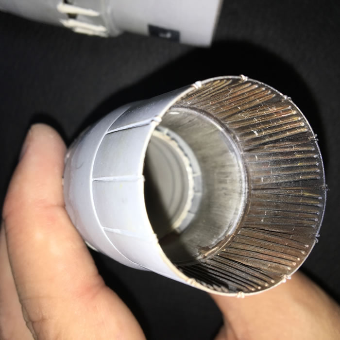
As I was deep into this build, Metallic Details from the Ukraine released two excellent sets for the SR-71. The first set was for the intake nacelles. I was too far along to use them by the time they became available. The second set was for the afterburner and grilles/vents located throughout the jet. I didn’t use the exhaust details. The grilles are directly glued over the molded in grilles. The etch is thin, however, they appear to be a little raised on the model. Thinner metal would make them look a little better. The same kit gives two nice nose gear doors each of which has a grille.
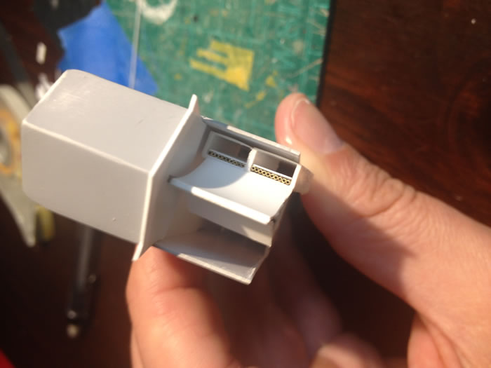
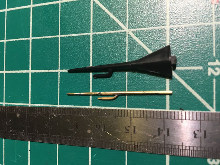
The kit pitot tube is rather thick and clunky. I decided to replace it by scratch-building one using Albion Alloys tubing that was soldered together. It’s a good thing I made my own pitot because it got knocked around several times during construction. I also soldered together thin pieces of brass to make the small pitots on the dorsal lip of each nacelle. The scratch-built FOD covers are held into place by red thread that loops around the nacelle pitots.
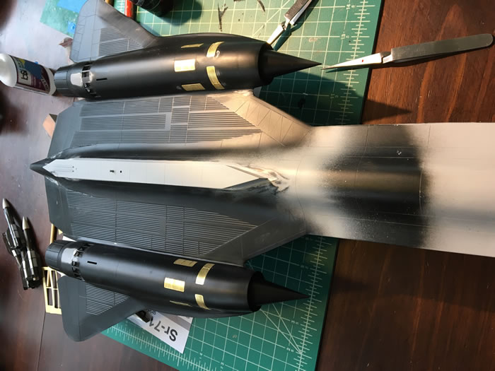
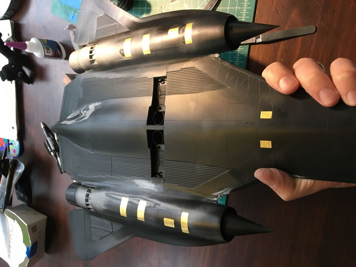
Prior to painting the model I sprayed Mr. Surfacer 1200 over the entire model to identify problem areas that I couldn’t see in the black plastic. I had to go back and fill the seam between the right nacelle and fuselage. I used Gunze metallic black for the entire model. (The vertical stabilizers were attached and seams filled prior to painting. I protected the painted stencils with Tamiya tape, which stayed on for the rest of the build.) I used a Grex Tritium airbrush with their new fan tip at about 20 psi. The fan tip worked great and allowed me to get excellent coverage without getting what I call “tracks” in the paint from using a regular tip. The fan tip shoots out a blade of paint, so having paint pile up isn’t an issue. The final flat clear coat of Alclad flat was done using the same parameters.
The Gunze paint dried with a semi-gloss finish. I went ahead and covered the entire model with Testors Metalizer Sealer to give a better surface for decals to adhere to. Unfortunately, the custom and rivet decals did everything they could to silver on me. I fixed these problems by slicing small holes in each decal and using either Mr. Mark Softer and/or Solvaset.
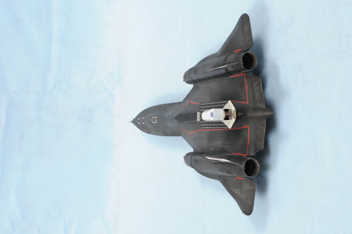
One area that stands out on the real jet are the “pie slices” that are on the leading and trailing edges of the jet. I took my metallic base coat and added different hues to either lighten or darken the paint. I randomly masked off slices and went around the top and bottom painting each one. I found the result to look very convincing and give the model more character.
The last challenge of this build was how to weather a black model. It looked good just sitting there in all black, but it lacked dimension. I toyed around with the idea of a panel wash and using some of the powdered weathering products from AK International. I tried this out on a scrapped model with unconvincing results. It didn’t look right. A friend of mine suggested that I try a “dot filter” technique. I took small dabs of oil paint such as ochres, umbers, siennas, yellow, gray, and white and placed random dots of these colors on the model. After it was dotted up I took a stiff bristled brush and wisped it back and forth along the model at 90 degrees to the center. It did a good job of adding some warmth and dimension to what was a particularly bland scheme.
Once the flat coat was on, the last thing to do besides gluing on the gear doors and FOD covers was to attach the LASRE. Only a couple of drops of epoxy are holding the LASRE to the canoe.
I’m very happy with the finished results. I have a one of a kind build using techniques and materials I have never used before. The build was frustrating at times due to the bottom seam running through the pie slices and the bad fit of the Cutting Edge parts to the kit. Building an SR-71 had been on my bucket list for several years, however, the quality of the Testors kit was enough of deterrence to avoid building it for a long time. Tony Landis’ book was the inspiration I needed to attempt something I had never done before.
References
Model, Images and Text Copyright ©
2021 by Chris Derks
Page Created 12 January, 2021
Last Updated
12 February, 2021
Back to HyperScale Main Page

|
 Home
| What's New | Features | Gallery | Reviews | Reference | Resource Guides | Forum |
Home
| What's New | Features | Gallery | Reviews | Reference | Resource Guides | Forum |