|
Bell
OH-58D Kiowa Warrior |
Bell OH-58D Kiowa Warrior "Black Death"
by
Floyd S. Werner, Jr.
|
Bell
OH-58D Kiowa Warrior |
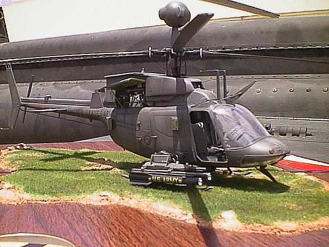
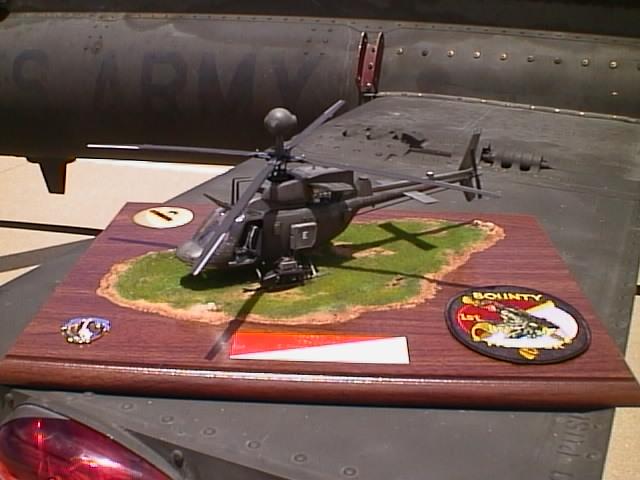
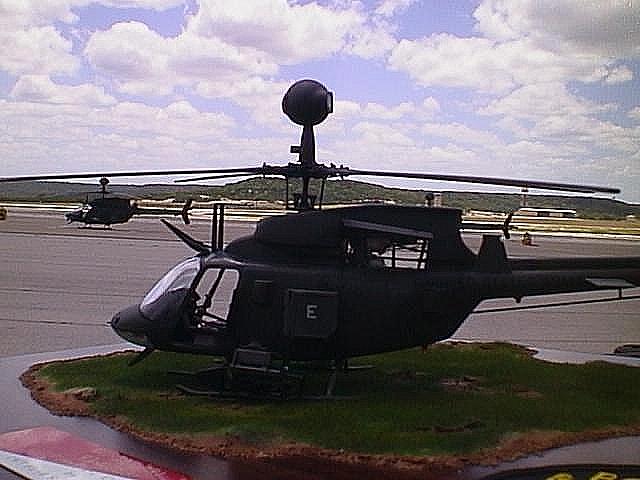
MRC 1/35th Scale Bell OH-58D Kiowa Warrior "Black Death"
B a c k g r o u n d |
Just to prove that I can build something other than a German airplane (and because someone paid me) I started the Kiowa Warrior.
When I flew Cobras I knew better than to try to model it because I would want to put every little detail into it. When I purchased the Warrior and a friend asked me to build one for him I reluctantly said "yeah why not?"
Boy, did I become overwhelmed by being overly-familiar with the subject! I needed to make many modifications to represent the aircraft assigned to my unit, 1st Squadron, 7th Cavalry Regiment, 1st Cavalry Division at Ft Hood. Our helicopters are the most advanced version of the Warrior and the kit was based on one of the earliest models. The Allison Engine representative I was building this for wanted an aircraft with a C250/R-3 engine with a little detail in it.
The Kiowa was fielded in the late 1960s and forced upon the Army by politics. Lady Bird Johnson held major stocks in Bell Helicopter. Although under-powered it was sent to Vietnam to replace the OH-6. The Army pilots nicknamed it the "5.8" - not quite as good as the OH-6. It has served with the Army in various versions since then.
In 1981, Bell won the Army Helicopter Improvement Program (AHIP). Financed by the Field Artillery for a spotter helicopter led to this helicopter being be shunned by Army Aviation. It was initially unarmed, but contained a night targeting system (Thermal Imaging System [TIS]) and a day targeting system (TeleVision System [TVS]), both incorporated laser range finding capability. The artillery people incorporated a digital call for fire that made the helicopter lethal.
Task Force 118 was developed at Ft Bragg to test the ability of the helicopter to carry armament. It was deployed to the Persian Gulf to combat Iranian gunboats mining the Strait of Hormuze. They performed this mission with great success, destroying many of the mine layers without loss through enemy contact. After the Army Warfighting Experiment, the Army developed the Digital Warrior, the OH-58D ( R ). 1-7 Cav was the first unit to receive this new helicopter and field it. Boy was that fun.
Imagine a new electronic system with all the things that could go wrong - and they did!
Some of the improvements to the R were the incorporation of the R-3 engine (FADEC), new intakes and new Improved Multi-System Processors (IMSP). The Warrior continued to be able to employ the Hellfire Missile System, .50 Cal Gun System (man is that thing loud from the left seat), 2.75" Rocket Launchers, or the Air to Air Stinger (ATAS).
So with the subject readily available I jumped right in.
C o n s t r u c t i o n |
First thing I noticed was that some panel lines were wrong or missing. These were filled and rescribed as necessary.
The cockpit looks good out of the box, but it was missing some details and looked a bit sparse.
I added all the switches to the cyclics (sticks), collective (up/down lever) and instrument panel (FADEC switch). I also made a first aid kit out of epoxy putty and placed it on the right side opposite of the fire extinguisher. One area to deviate from the instructions is DON'T put the glareshield on at this time. Wait until just before putting the windscreen on. It gets in the way now.
The Black Boxes in the back are fairly accurate but we NEVER have the back doors off anyway so who cares - you can't see them anyhow.
Overall I liked the interior. It could use more busy stuff to show how cramped the cockpit really is but it was really useable. One obvious omission were the seatbelts and shoulder harnesses. These are easily fabricated from tracing paper and Eduard photo-etch latches. The seat are off-white with the leather strap under the buckle being leather coloured (imagine that). The Multi Function Displays (MFD) should be painted flat black along with the rest of the instrument panel and then painted Tamiya Clear Green. If you look at mine you will notice a tank on the co-pliot/gunner MFD. It happened by chance and not by design but who cares - it looks great.
The next step is the engine and transmission. I detailed the engine with wire, solder, and tubing. One major problem with the engine is in the power turbine area that is very square. All Warriors have a heat shield mounted to the bottom that takes on a curved and rounded look. I made this out of brass sheet and formed it. It looks convincing.
Our helicopters have a HMU on the right side that has a prominent crinkled aluminum foil cover. Paint the engine area pan titanium, as well as the fore and aft walls. The area around the transmission should be Zinc. Don't forget to paint the underside of the engine area black as it helps form the part of the interior.
NOTE: do not put the back wall (Part B-30) on just yet. The wall sits about 1mm too far forward. It is more easily repositioned aft when glued in the fuselage half.
Painting the engine is, from front to back, steel (B-21), neutral gray (B-25+26), burnt metal (B-22+23), Magnesium (B-19+24), White (B-20) and copper for B-18. All engine mounts are zinc.
I didn't paint the transmission light gray until Step 5 when I installed B-34. Every other part in step 5 is black. I didn't attach the Main Rotor Mast to the transmission because of having to move the helicopter. A dry brush of light gray brings out the detail.
Forget the pilots, but if you must paint them try this trick. Paint one like BDUs and the other in a one piece sage green colored flight suit. We use both. The helmets should be helicopter green, more on that later. Boots are black and gloves are gray-green. You'll notice I didn't give FS numbers and that is because the flight suits change colors a lot as does the other flight issue. Seat belts should be off white as stated earlier.
Our helicopters have new intakes and these have to be, dare I say it, scratchbuilt. At first I dreaded this part of the assembly, but other parts of the construction were tougher. I started this modification by laying down a .40 sheet for the bottom of the panel which is very straight. I also put a .45 dowel at the opening for the engine compartment from the top to the .40. This gives a nice shape to the aft part of the cowling. After reinforcing the .40 shelf with .80 channel I taped up the area around the cowlings to protect them. I used epoxy putty (for the first time) and molded them at the hangar to make sure I was getting the correct shape. The cowlings have a weird shape that is difficult to match and photos really don't do it justice. Using techniques taught to me by Milton (Thank you), I smoothed the epoxy with water. I tried to make the panel lines at this time. It didn't work.
Later I filled and rescribed them. You say, "But Floyd, this leaves a seam at the top of the cowling when assembled." So the real helicopter has this panel line. I smoothed the putty at the top cowling line and later scribed the top part.
CAUTION: the next step is important. Assemble the sub-assemblies together; dry fitting them as you go with the fuselage halves. I screwed mine up and had to do lots of work to get the windshield to fit. I had to saw off about 1/8th" of the transmission area so the windshield would fit.
Now come the fuselage halves. First off we fly with the crew doors off most of the time so get rid of them. Second the avionics compartment should be left out because it is way too small and not very accurate.
Next decide what weapon system to hang on the outside. If you want the .50 Cal then don't forget to open up the holes in the fuselage. You must open the holes if you want the AVR-2 laser sensors on the doors and fuselage. I had a problem assembling the halves. The cockpit area is a little too wide and needs to be thinned a little bit. After getting them together I discovered that the windshield didn't fit well at all. Now was the time to saw and dry fit the clear parts. Hold off putting these on for now it will save time and trouble in the next step. Add the avionics doors and the electrical compartment door. If you are modeling an R3 then leave off part D-40. The R3 does not use Doppler anymore but uses GPS. This is easily built on the tail rotor driveshaft cover. It consists of two square sections that mount to the top of the cover. On top of these pieces is a white round disk. Use a Waldron punch set #6.
With the fuselage together I was feeling good about my progress. Oh how wrong I was. Helicopters, unlike airplanes, have things hanging all over the outside. This was a big pain now and later.
Add the little details like the door handles, the Wire Strike Protection System (WSPS), and the AVR-2s. For the WSPS substitute wire for the supports as this makes them more sturdy. This is also true of the HF antenna under the tailboom.
Don't worry if the antenna isn't straight - they get bent on the real aircraft anyway. Attach the vertical stabilizer. I broke off the tail stinger and had to replace it with wire. I recommend this anyway because it gets hit on everything during handling. Now is a good time to add the horizontal stabilizers. The landing gear should be built up separately and pinned to the fuselage bottom. If you forgot scribe the exhaust area.
Frank didn't want the ALQ-144 installed, thank God. The mount is easier to build than match a color for the disco light. The mount can be built by using .80 channel. Cut three equal lengths for the side and four smaller ones for the inside. Start by putting a longer one on the front and one on each side of the mount with the flat side out. Using the smaller ones with the channel out join the long section from the inside of the mount. This sounds more difficult than it actually is.
The Universal Weapons Pylons (UWP) - have you got the idea that this helicopter can't fly without acronyms? Like I was saying the UWPs are angled about 10 degrees aft. This is not shown on the instructions and I didn't notice mine being wrong until I was pre-flighting long after attaching them. Attach the windscreens and the fuselage is almost done.
I started the rotor system which is as close as you can get to the real thing. It builds up exactly like the 1-1 scale. There is one part of the instructions that need clarification. Part C-28 should fit through the yoke so that the arm is in front of the leading edge of the blade.
The other thing is that the pitch change links should be offset 45 degrees. The kit doesn't mention this but sort of shows this in the completed picture. Paint the inside of the Mast Mounted Sight (MMS) black and paint the larger of the lenses Tamiya smoke. With the exception of part C42 and the MMS, the entire rotor system is flat black. The leading edge of the blades is gloss black with the tips being aluminum outboard adjacent to the trim tabs.
The weapons are beautiful. Frank wanted Hellfire and .50 cal, can't blame him this is what I want on my helicopter when I need to use it for real. The Hellfire are beautiful and build quite nicely. Paint them glass black. The .50 is a real beauty. This thing looks ready to shoot 700 rounds a minute. One thing here the instructions aren't clear but the gun itself is angled to fit on the stub on part D-37. Paint the cage assembly gloss black and the gun flat black dry brushed with gray. I know this isn't gun metal but our guns are sprayed with a gray dry film lubricant. The worst part of the .50 cal system is the ammo chute. This is made out of vinyl and difficult to work with. I put the ammo can on after painting and weathering the fuselage.
P a i n t i n g , W e a t h e r i n g a n d D e c a l s |
Paint the helicopter MODEL MASTER ACRYLIC FS34031. Don't use any other color. I painted every color under the sun on some paint chips from a crashed helicopter and this is the only one that matches exactly. The Model Master Enamel is too gray. I have only seen two helicopters painted this gray. One was a Cobra, 952, in Bosnia and an OH-58C painted in Belgium. Just for the fun of it I used the enamel on the ammo box to compare colors. Our boxes are a different color and this worked well. The AVR-2 antennas are a dark green. . A gloss coat and then decal as normal. I used the kit decals and some Aeromaster letters to represent the first production R3, 95-00081.
Weathering was acheived by adding white to the FS34031 to highlight certain panels. Then I added a wash of Burnt Umber oils to the panel lines. Then dry brush with the enamel 34031 from Model Master. I knew I would find a good use for it. Then a real light dry brush of white to the very top of the helicopter. The exhaust was painted titanium (as is the real one) and then weathered with Tamiya clear blue, red and smoke. I am happy with the results. A dull coat seals the decals. Use pastels to add the dust where the crews work and silver for where the ground handling wheels attach, as well as, various screws and rivets.
Now add all the extra stuff like antennas, lights, missiles and gun. The missile and gun should be angled slightly up, 2 mils for those sticklers and 2 mils down for the .50 cal. I know that the manual says 0 mils but we found that 2 works better for the 1000-1500 shots. I added tubing to the weapon systems for the cables with Detail Masters compression fittings #2. These add a little to the appearance and connect the weapons to the helicopter. Don't forget the engine cowling doors. Add the .50 cal ammo chute and you are done.
C o n c l u s i o n |
This model was a lot of work, about 150 hours, and I learned many tricks for building my own Warrior in the future. Overall the appearance is correct but you will have to do some updating, especially the cowlings. As there are few references available let me know if you want pictures - you can use mine or I'll take some for you.
I recommend this kit to modelers with experience, even if they don't build the forward cowlings. I have seen this built out of the box and it can be built well.
I am very happy with the end results and I hope Frank is too!
Floyd S. Werner, Jr.
IPMS # 26266
HORRIDO!
Remember modeling is fun!
Back to HyperScale Main Page
Back to Features Page