Home
| What's New |
Features |
Gallery |
Reviews |
Reference |
Forum |
Search
Home
| What's New |
Features |
Gallery |
Reviews |
Reference |
Forum |
Search
|
|
|
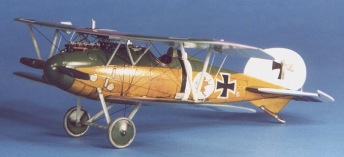
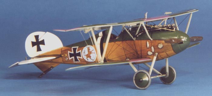
Albatros D V/Va by Bob Laskodi
The Albatros DV/Va was the "Rodney Dangerfield" of German fighter aircraft during WWI in that it did not get the respect that it deserved. While it was not a significant improvement over the Albatros D.III aircraft that dominated the Allied forces when it was deployed in early 1917, it was a very effective aircraft in the hands of a well-trained pilot. Many of the leading German aces including Manfred von Richtofen scored many kills in this variant. In fact, the Albatros DV/DVa was the most widely produced fighter aircraft in Germany and bore the brunt of the aerial war from mid-1917 until mid-1918 and boldly soldiered on until the Armistice. The aircraft modeled is that flown by HPTM Eduard von Schleich in mid-1917. Von Schleich survived the war with 35 victories and served as the CO of Jasta 21. He was a highly respected aviator and received many decorations including the Orden Pour le Merite (Blue Max), Iron Cross 1st and 2nd Class, Knights Cross, and the Military Order of St. Henry.
The kit is Eduard's Albatros DV kit (8013) which also includes all the necessary parts for the Albatros DVa variant. It is not currently in production, but kits can still be found. I got mine dirt cheap since it is discontinued, $10 USD. It is a mixed media kit and consists of injected molded plastic (33 parts), two sheets of photo-etch detail parts (36 items), finely cast white metal engine components (4 parts), an acetate sheet for the windscreen and instrument dials, and the usual Czech printed decal sheet with options for Goering's Jasta 27 Albatros DV, or von Hipple's Jasta 5 Albatros DVa.
The plastic parts have significant amounts of flash/mold lines that require clean up and do not have any locating pins or holes and these must be drilled. The instruction sheet is the usual four page diagram assembly with marked color painting guidelines, and is clearly indicated with the modifications needed to build the DVa variant. In addition, a one page color sheet is provided showing the final painting and decaling schemes for both variants (unfortunately, no color information is provided with this sheet so you are on your own with regards to color selection, however, the colors are fairly accurately rendered on my sheet).
I started with my usual warm, dish soap water wash of the plastic, metal, and photo-etch components and followed with a cold water rinse. The parts were patted dry with a paper towel and let dry overnight. The wash does really help on Eduard kits, especially on the photo-etch parts. I then pre-painted all the parts as indicated in the instructions, with the exception of the fuselage walls, bulkheads, floors, and engine mount floor which I covered with Tauro wood grain decal (the only wood grain decal still in production). The stringer detail on the fuselage sidewalls were then hand painted Testors Model Master (TMM) French Chestnut and given a light wash of burnt umber. Assembly of the fuselage components was accomplished using super-thin superglue. Assembly proceeded as described in the instructions, however two problems are noted. First, the pilot yoke/stick assembly as indicated in the instructions is incorrect as it is reversed. Further on in the instructions is the view, which shows the assembly of the sub-assemblies into the fuselage, that view is correct. The second problem involves the installation of the bulkheads. Early Eduard models are not known for good engineering and fit problems arise. Mine was no exception, and since I built the cockpit as sub-assemblies the bulkheads would not fit correctly. It is very difficult to get a good fit of the magazine to its bulkhead and then to its correct opening in the fuselage. A lot of grinding with a Dremel erased these fit problems. I then skipped over the instruction sequence for the machine guns and feed belts and started on the engine. The white metal engine components are very nicely cast, with little clean-up work needed. I painted them, assembled them together, and then gave the whole assembly a heavy wash of black. I installed the engine floorboard to the fuselage side, wrapped the top half of the engine (exhaust stack was not installed yet) in parafilm, and installed the engine into the fuselage with superglue. I then closed up the fuselage, said bad words about the bulkhead fit problem, fixed them as described, and used liquid cement to glue the fuselage halves together. I then separated (cut) the control surfaces from the upper wing, horizontal stabilizer, and tail fin as I was going to position these in accordance with the way the controls were glued into the cockpit (left turn). Next, I glued with liquid cement the headrest fairing, the tail fin, the skid fairing, and lower wing to the fuselage. When I removed the stabilizer control surfaces, I was left with a right and left hand part for the stabilizer. In order to insure a correct join to the fuselage, I installed small pieces of hard music wire into the stabilizers and carefully drilled corresponding mounting holes into the fuselage. This worked perfectly and with a little bit of tweaking I cemented the stabilizers to the fuselage in perfect alignment that did not require any putty. I then cleaned up the separated control surfaces with sanding sticks and used liquid cement to rejoin them to their correct position and locations. All joins were then sanded smooth, and putty was used to fill some minor gaps in the lower wing to fuselage join. Then I drilled all of the rigging, strut, and landing gear mounting holes as described in the instructions. Next stop was the paint shop.
The model was painted, decaled, and weathered as described in the following subsections and then final assembly took place. I installed the interplane and cabane struts into place using relatively large amounts of super-thin superglue. This is done to insure a relatively fragile model does not explode in later life! The cabane struts were glued to the fuselage body in correct spacing for the upper wing using a caliper to exactly set the distance and the interplane struts were glued to the bottom of the top wing. Basically, by applying small drops of super-thin superglue carefully around the strut to form a small bead around the strut base you can make the model much stronger. Do not use an excessive amount, just enough for a thin bead. If you use super-thin superglue carefully applied, you can form a perfect bead around the strut base. I then installed the radiator assembly to the lower portion of the upper wing and the aileron actuators (parts PE 18 & 24) as described in the instructions. Next I drilled small holes in the radiator to fit short sections of corresponding diameter brass wire for the radiator to engine piping. Now it was time to return to the machine guns. Assemble the guns as shown in the instructions. A tip to ease assembly is to use a correct length of hypo tubing (not a little piece as shown) superglued to a drilled hole into the gun breech opening. By carefully aligning this rod, mounting and aligning of the cooling jackets will be much easier, just superglue them to the bottom of the rod. Make sure you anneal (heat in a flame until red hot) the jackets and you will be rewarded with a truly circular jacket. Roll the jackets around the correct size circular rod (styrene rod works) to get a perfect jacket. Place the jacket seam to the bottom and no one will even see it! I painted the machine guns in Testors Metallizer Gun Metal and dry brushed with Floquil Gun Metal. Good luck in mounting the photo-etch ammo feeds, even more luck is required to get them in the proper shape shown into the magazine! Now onto the fun part, putting on the top wing! Actually, this task went smoothly with no problems. Since the cabane struts are made of metal and already fixed in the correct position on the fuselage, the top wing snapped into place in the correct position. I placed the upper wing on the work bench and turned the fuselage upside down to mount it. First set the interplane struts into place in their correct holes (remember to drill them out), then flex the metal cabane struts into their respective holes and bingo, the wing is in place. I used small rubber bands to help hold both wings in place and then checked alignment of the top to bottom wing. When all was to my liking, superglue the struts to wing using the bead technique described above. A word of caution, let the glue cure fully before moving the model and you will be rewarded with a relatively strong top wing join.
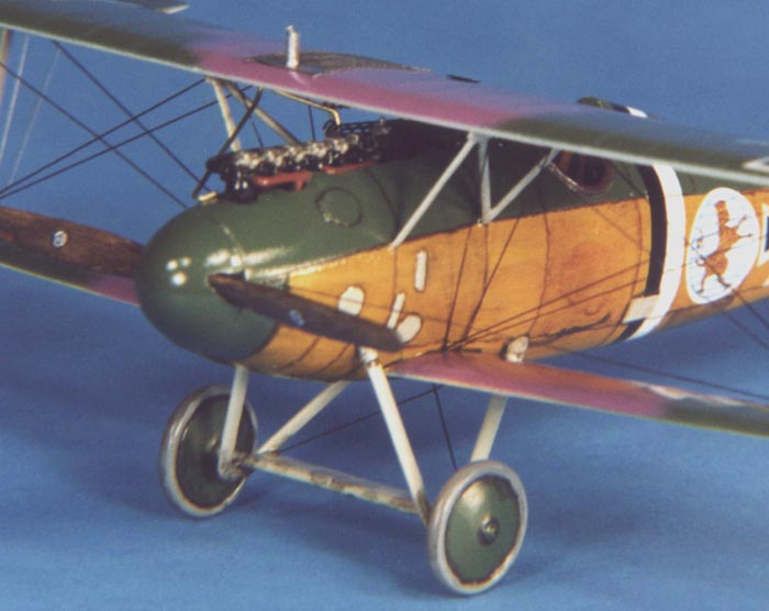
Now on to the next challenge, installing the landing gear! Installing landing gear on early Eduard models is a challenge at best and extremely frustrating at worst. Since there are really no locating pins and holes to speak of, many people install metal pins into the ends to help ease this task. I use a simpler method in that I build a simple jig. My jig is nothing but a small block of styrofoam packing material that comes in protective packaging of electronics goods. One TV and you are set for life! Take a small block of styrofoam and mark the width of the landing gear on it. Carefully measure all dimensions and mark them on the block to maintain the correct angles. Push the legs of the landing gear into the block and set the approximate width of the landing gear axle. Then place the axle into place on the legs (you did remember to drill those holes?) and after carefully aligning everything glue it in place. Let the glue fully cure then paint the assembly, let dry, and remove it from the block. Glue one leg into place with superglue, let set, then glue the remaining legs into place. Use the superglue bead technique described for the struts and you will be rewarded with a relatively strong set of landing gear. Lastly install the painted wheels into place on the axle with superglue, and the tail skid. Carefully install the exhaust stack, propeller, and propeller spinner with superglue. I drilled out the exhaust stacks, painted them Testors Metallizer Burnt Iron and then applied a heavy wash of Rustall. The propeller was painted by using a base coat of dark yellow, and successive light dry brushing using a rake brush of TMM raw sienna, raw umber, burnt sienna, and burnt umber to replicate the wood grain. The rake brush does a fairly good job of replicating wood grain without resorting to decals, which are a pain on a small part like a prop. Install all the remaining pieces (but not the top wing radiator and aileron actuators) as indicated in the instructions to prepare for the next fun job of rigging a WWI biplane! Truthfully, rigging an airplane is not difficult. It is time consuming and tedious. First you need a plan. You should have a rigging plan in place before you even start construction of the model so you can pre-drill holes and plan for obstruction problems. Study the instructions carefully and figure out where every rigging wire needs to go. Each kit will be different and will have a different plan. For example, the Eduard Albatros has photo-etch cabane struts that are a pain to drill holes in since the metal deforms easily. In this case, I saw that six rigging wires pass through each cabane. I drilled a small hole with my smallest bit (#80, .0135 in) through the lower wing and attached four long rigging wires through it with extra thin superglue. The nice thing about the Albatros is it has a small metal plate (PE 6) to cover this hole from the bottom of the wing. I then ran a wire to the forward upper interplane strut, one to the rear upper interplane strut, one wire through the forward upper cabane strut around the wing attachment piece then down to the bottom of the interplane strut, and lastly one wire through the rear upper cabane strut around the wing attachment piece then down to the bottom of the interplane strut. I no longer drill holes through struts for rigging as it may pull out in time. I wrap the end of the wire completely around the strut and secure it with a tiny drop of extra thin superglue using the bead technique described for struts. Rig the rest of the model as indicated on the instruction sheet. For rigging wire I use a product sold in sewing shops called invisible thread (which is the same as monofilament fishing line) that is .005 inches in diameter. It is easy to use, just paint it whatever color you like (I finally found a use for those Testors paint markers that I bought! Flat black is best for appearance, silver is the more realistic color but doesn't show up as well in pictures), is easy to pull taut (use a hemostat as that vital third hand to keep the wire taut), is easy to thread around/through stuff, and more importantly, you can trim it flush easily with a new XACTO blade. No more metal wire or stretched sprue for me! Finally, the model is almost done. The last step is to install the remaining parts to the upper wing (top wing radiator and aileron actuators).
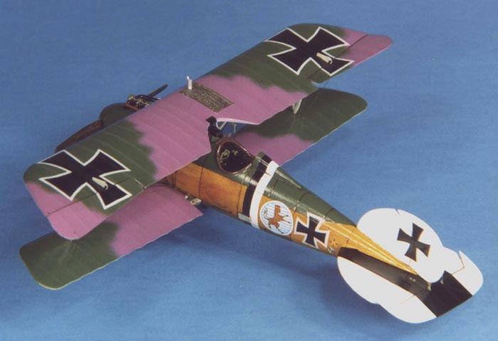
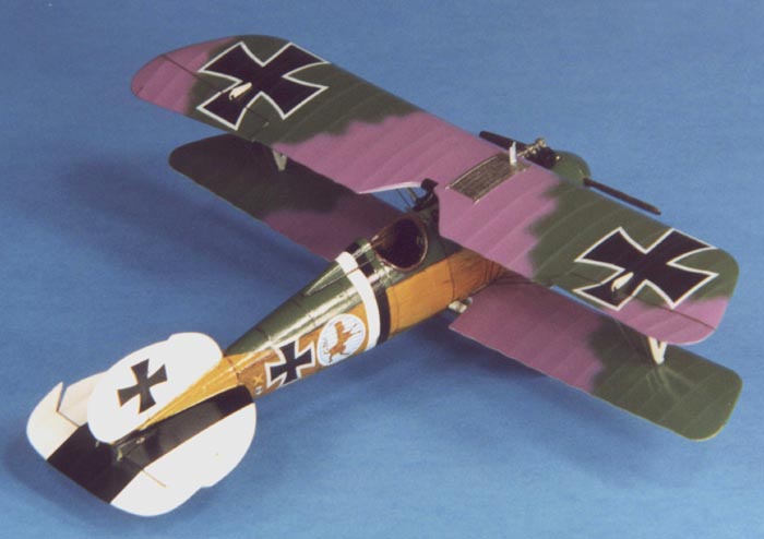
As mentioned above, all painting was done after completion of the fuselage and attachment of the lower wing fairly early in the construction process. I started first by airbrushing the entire fuselage and tail section Polly Scale (PS) Acrylic White (RLM21). The white also served as the base color for my wood grain finish discussed later. I then shot the underside of the wings with Gunze Sangyo Blue (H314) for the underside blue. The top wings were sprayed freehand with PS German Mauve and TMM French Khaki. Next I replicated the wood grain finish on the fuselage. Previously, I had good success using a dry brushing technique with a rake brush that I used for smaller pieces. Starting with the white finish, I lightly dry brushed successive colors of TMM Raw Umber, Raw Sienna, Burnt Sienna, and Burnt Umber atop each other in a random pattern. I then dry brushed with a rake brush Humbrol Oak (#71) to randomly cover and let peek through the underlying dry brushed colors in an approximate wood grain pattern. After letting this cure overnight I shot many coats of Gunze Sangyo (GS) Clear Yellow (H91) to get that Albatros wood grain yellow look. A word of caution, you must apply many, many, many coats of clear yellow (I probably did about 10-12) to get that nice rich honey amber hue. After letting the yellow coat cure for a day I then masked the forward fuselage and shot TMM French Khaki. After a day of drying time, I sprayed a light coat of Future in preparation for decaling and applied the decals. For the decals I used Aeromaster decal sheet 48-181, Albatros Fighters Part 1.
I then sealed everything with a light coat of PS Flat Finish to provide a surface for pastel application. I then used a pastel pencil to lightly highlight the rib detail on the wings/tail surfaces. I then randomly applied some ground up burnt umber pastels with a soft brush to simulate dirt staining on the lower surfaces. Lastly, I applied a heavy burnt umber oil wash to the wheels and control surface joins. I then finished final assembly of the models as described above. Lastly, I lightly touched up by hand painting with the appropriate colored paints all flaws and the areas that were covered in superglue including strut/rigging attachment points. Next was a technique that helps hide minor flaws in a model finish caused by superglue and painting successive coats. It is very simple, just spray the entire model with several coats of a mix of equal parts Future, Tamiya Flat Base (X21), and rubbing alcohol. This will hide almost all minor flaws in the finish, but will not cover major flaws so it is not a substitute for poor modeling technique. Finally, several coats of straight Future was shot to achieve the final glossy finish common to most WWI aircraft.
I highly recommend this kit for experienced builders, as it is a very accurate and good representation of the important Albatros DV/DVa airplane. Less experienced modelers could have a successful build with some care but the size of some of the photo-etch parts (less than 1 mm!) coupled with fit problems discussed earlier will make it a challenge. Since the model has been discontinued it may be tough to find, but the price on it is likely to be very attractive. This was undoubtedly the best and most accurate $10 (USD) model I have ever built and I returned to the hobby shop and purchased his entire remaining stock so look for more gallery entries in the future!
Model, Text and Images Copyright ©
2000 by Bob Laskodi
|