Home
| What's New |
Features |
Gallery |
Reviews |
Reference |
Forum |
Search
Home
| What's New |
Features |
Gallery |
Reviews |
Reference |
Forum |
Search
|
|
|
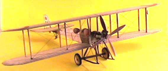
BE2a by Mark A. Johnson
This is my BE2a paper card model, available in printed form or downloadable from Paper Paradise. Designed by Steve Bucher. Purchased-May 2000, Built - May 2000 This is the first model published by Steve Bucher and I hope he will design many more. Steve welcomes any questions you may have during the building. Try that with a Polish kit! He is also looking for suggestions for future projects.
BE2 therefore implies there was a BE1. I found one reference that says the BE2 was simply an improved BE1. The BE2 s started service as observation/combat aircraft and actually took part in bombing raids. With the increase in counter-air activities in early 1915, the type was soon relegated to second line duties including training and Homeland Defense. It is in this capacity that the BE2 is best known with the BE2e being the version with the highest production numbers. A BE2c was the aircraft used to shoot down the first Zeppelin over England on Sep 2, 1916. Altogether over 3000 BEs of all types were built. BEs were used in supporting roles at least until 1918. The BE2a that this model represents varies from the later, more common versions, primarily by the addition of ailerons. The "a" used wing warping for lateral control. The later airplanes also moved the observer from the front to the rear cockpit and some included a rear machine gun.
I received my model by email directly from Steve. He sent a .pdf file containing the two sheets of color parts to be printed on card. Another sheet included engine parts also printed on card, one sheet of rolled parts printed on regular paper (including the propeller hub, the axle, and the engine cylinders), and four pages of instructions. The instructions include a full-page two-view diagram of the model that was especially helpful with the rigging. The files also included 9 .jpg pictures of the completed model. I printed the main components on a cream-colored 65lb card stock. I think the cream color is better than white since it makes the cut edges easier to hide and more closely represents the linen fabric that originally covered these airplanes. The underlying color also slightly enhances the printed colors. My initial impression was that the graphics are a little fuzzy, but this actually improved the realism of the finished model at this small scale.
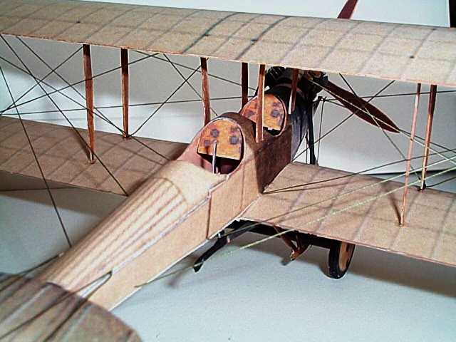
Fuselage Assembly The fuselage is built up from three simple pieces with no internal structure. After adding the seats and instrument panels the structure is sufficiently rigid without bulkheads or stringers. The seats are drawn a little high so you can trim them to match exactly the top profile of the cockpit. I was a little confused at the rear of the fuselage. If you follow the profile on the top and bottom panels, you have the two sides rounded for the last 10mm before meeting at the tail. But the flanges provided on the side panels, for mounting the top and bottom, prevent any curvature in this area and tend to force a straight taper to a sharp trailing edge. The drawings do not contain an overhead view to confirm the correct profile. Checking my own reference material on the BE2c suggest that the curved profile is correct. To achieve this shape cut some v shaped notches in the fuselage flanges, following the top and bottom panels as a guide. As recommended in the instructions I painted the visible areas inside the fuselage and the seat back with a light brown flat enamel.
Wings and Tail Surfaces
Top wing assembly is straightforward but as with any biplane requires patience to get a good result. The wings were assembled with no dihedral, which I suspect is an error. Although I could not find an original picture of a BE2a, pictures of BE2cs and BE2es show a small dihedral angle on both upper and lower wings. Because the "a" and "c" had different control systems, it's possible that the "a" had flat wings. As an aside, the biggest reported problem with the BEs was that they had too much stability. Although this made them safe and well suited for observation missions, it eliminated the pilot's ability to take evasive action when attacked. To install the top wing, first install the outboard wing struts and let dry completely. Then glue on the top wing and let it dry. Finally add the inboard and fuselage struts.
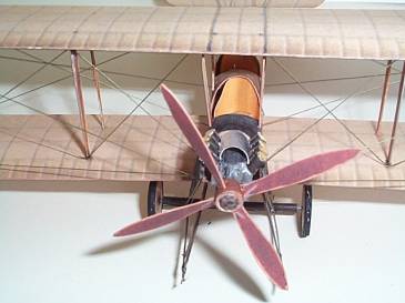
The undercarriage is a particularly delicate assembly but looks very good when completed and has sufficient strength to support the model. I rolled the axle over a thin piece of music wire and attached the wheels to the same wire, allowing the wheels to turn freely.
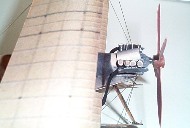
Engine and Propeller Assembly The engine is a high point on this model. My references say that the BE2a used a 60 hp Renault V-8 engine. I was unable to find a picture of this engine. Later BEs used the 90hp RAF 1a V-8 engine. The kit engine looks very much like the RAF 1a that you can see at the Air Force Museum web site. The museum has a gallery for aircraft engines, which includes a great picture of the RAF 1a. Installed in the BE, the engine is totally exposed and looks great when assembled as is. With a few extra bits and pieces it can be detailed to make it really stand out. To create the engine, many parts are stacked to build a solid paper block, which is then trimmed to final shape. The instructions say to paint the entire assembly black. I painted the block aluminum and left the cylinders black.
Rigging There is a lot of rigging on this model. It adds much to the finished effect and is therefore a worthwhile effort but if you're not up to it don't worry, the model still looks good without it. If you do want to add the rigging, the drawings in the instructions are a pretty good guide, although I could have used an overhead view for some areas. Don't be tempted to add fore and aft cross bracing between wing struts. Although this is visible in photographs of BE2s, it only applies to the later models with ailerons and is not appropriate to this wing-warping machine.
This was a relatively easy project that produced a very nice looking model for a very low price. I spent about one week of evenings assembling it. I highly recommend this kit to any antique airplane lover and anxiously await Steve's next effort. I heard he is working on a FE. I'd really like to see him try a DH-2! This BE2a kit is available online from Paper Paradise Model, Images and Text Copyright © 2000 by
Mark A. Johnson
|
 The BE2a
modeled represents an RNAS aircraft operated from Feb 1914 to Jan 1916. This
airplane makes an interesting model subject because it is so frail and detailed,
and also because it's an important but rarely seen type. In researching this
project I discovered the naming convention used by the Royal Aircraft Factory
during WWI. BE stands for Bleriot Experimental. This was because Bleriot was
credited with being the first to perfect the tractor configuration. All BEs
therefore have the engine in the front. FE by contrast stands for Farman
Experimental. Farman was credited with perfecting the pusher configuration, with
the engine in the rear. I'm not sure why the Wright's were not given credit for
this unless it's because they actually placed the engine in the middle of the
wing. Other names included SE for Scouting Experimental, hence the SE-5.
The BE2a
modeled represents an RNAS aircraft operated from Feb 1914 to Jan 1916. This
airplane makes an interesting model subject because it is so frail and detailed,
and also because it's an important but rarely seen type. In researching this
project I discovered the naming convention used by the Royal Aircraft Factory
during WWI. BE stands for Bleriot Experimental. This was because Bleriot was
credited with being the first to perfect the tractor configuration. All BEs
therefore have the engine in the front. FE by contrast stands for Farman
Experimental. Farman was credited with perfecting the pusher configuration, with
the engine in the rear. I'm not sure why the Wright's were not given credit for
this unless it's because they actually placed the engine in the middle of the
wing. Other names included SE for Scouting Experimental, hence the SE-5.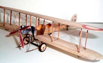 The
directions say to score the wings at the LE then fold over and glue. When the
glue has dried you can roll a dowel over the assembly to shape the airfoil. To
give the wings a little extra thickness (at this scale the max thickness should
be only about 2-3 mm) score the LE then before folding roll separately the
curvature in the Upper and lower panels. Be sure to reverse the curvature on the
lower panel to duplicate the undercamber of the prototype. Then fold over the
wing and glue only the trailing edges together. This yields a reasonably rigid
structure. For even more strength you could insert a 2 or 3 mm spar. Remember
that the maximum thickness of an airfoil should be app. 1/3 of the chord back
from the leading edge. In mounting the lower wing to the fuselage I cut away the
top center section of the wing, inserted a flat toothpick as a mini spar to
replace the lost strength, and notched the fuselage floor to accept the spar.
The
directions say to score the wings at the LE then fold over and glue. When the
glue has dried you can roll a dowel over the assembly to shape the airfoil. To
give the wings a little extra thickness (at this scale the max thickness should
be only about 2-3 mm) score the LE then before folding roll separately the
curvature in the Upper and lower panels. Be sure to reverse the curvature on the
lower panel to duplicate the undercamber of the prototype. Then fold over the
wing and glue only the trailing edges together. This yields a reasonably rigid
structure. For even more strength you could insert a 2 or 3 mm spar. Remember
that the maximum thickness of an airfoil should be app. 1/3 of the chord back
from the leading edge. In mounting the lower wing to the fuselage I cut away the
top center section of the wing, inserted a flat toothpick as a mini spar to
replace the lost strength, and notched the fuselage floor to accept the spar.