Home
| What's New |
Features |
Gallery |
Reviews |
Reference |
Forum |
Search
Home
| What's New |
Features |
Gallery |
Reviews |
Reference |
Forum |
Search
|
|
Beaufighter
Mk. 21
|
 |
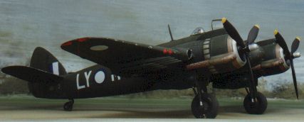
Beaufighter
Mk. 21 of 30 Squadron, |
Tamiya's Beaufighter is here at last! I’ve waited a long lime for this one.
I already had two of the excellent vacform Beaufighters by Falcon. I had even started to remove the backing sheet from the major components on one before "vacform terror" overtook me.
So is the long wait worthwhile?
The box contains six sprues of Tamiya’s now standard medium grey plastic, one sprue of clear plastic, two "poly cap" fasteners for the propellers and markings for three aircraft. In addition to the instructions there is an A5 sheet with a 1/48 scale diagram of both fuselage sides and upper surface camouflage demarcation. The size of the model is emphasised here - the upper surface drawing has to be split up to fit on this large sheet of paper.
Surface detail is as one expects from Tamiya: sharply-recessed panel lines combined with raised detail where appropriate. A large number of ejector pin marks are present on the inner surface of some parts including the fuselage and wheel bay doors, but these are invisible when the model is completed.
Let’s take a more detailed look at what’s in the box.
Options Out-Of-The-Box
Options include a thimble nose (a la TFX) and a forward fuselage-mounted auto-pilot housing as used on the Australian Mk 21 (hooray!) although neither of these items is mentioned in the instructions. A mysterious alternative tailwheel is also present. Options which are mentioned include eight rockets for the attack bomber version, clear OF loop housing, clear or framed rear canopy and a variety of antennae for the night fighter version.
|
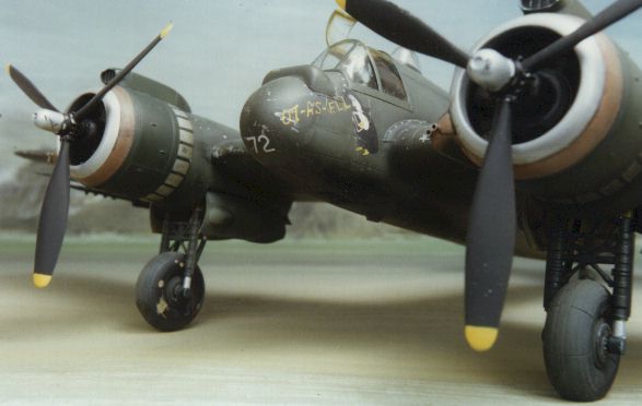
| The Beaufighter was sometimes described as a pair of engines closely followed by an aircraft. This is why! |
The escape hatch in the top of the pilot’s canopy may be positioned open, and both entry hatches may be built movable (they hinge open and closed - I kid you not). Also of interest are options not contained in the kit. The large, late-style horizontal stabilisers with dihedral is the only tail configuration supplied, eliminating the option of a Mark I or an early
Mark VI out of the box. Also absent are the non-damped exhaust stacks. Although the thimble nose for the TFX is included, the dorsal fin found on some later TFXs is not, nor is the torpedo.
Nevertheless, a wide variety of subjects are possible out of the box including most Mk VIs, many Mk Xs and almost any Australian Mk 21 (for which I will be forever grateful).
Step by Step
Cockpit
Construction commences with the adequately-detailed cockpit. Although the cockpit tub is far too shallow, the fuselage interior is lined with structural detail. The cockpit and navigator’s position is made up of fourteen parts. A series of decals portrays instrument faces, which are applied to the instrument panes after painting. I used this option but found the result less than totally convincing. To enhance realism, I used a drop of Micro Krystal Kleer on each of the instruments to represent lenses. Harnesses are supplied as decals. If you intend to use them I would recommend cutting them out and using them with the paper backing on. I used brass harnesses myself. Pilot and navigator figures are also included if you don’t want to use the harnesses.
Super-detailers have the choice of either chopping up and relocating the cockpit tub, or purchasing one of the excellent after-market resin cockpits now available from Cutting Edge and True Details.
Fuselage
When joining the fuselage halves, the only significant gap was around the navigator’s lower hatch. I therefore glued this shut and used a little filler to fix the problem. I also applied a tiny trail of putty on the top fuselage join.
The cannon ports on the lower fuselage are quite prominent, and require drilling out. This is best done after the fuselage halves have been joined.
The five-piece wing assembly is typically Tamiya. It has been designed to ensure perfect dihedral and a secure fit to the fuselage. I wish more model companies put this much thought into construction breakdown. The wings include separate clear landing lights and navigation lights on each wingtip. This was a good move - the navigation lights on the Beaufighter were too big to be ignored!
A tip: if you are building a rocket-equipped Beaufighter: don’t forget to open up the holes in the lower wing for the rocket rails before you glue the halves together (like I did!).
Wing and Tail Assemblies
The fit of the entire wing assembly, and the subsequent wing to fuselage fit, is close to perfect. I thinned down the trailing edges of the wings slightly using the back of a hobby knife.
The tail assembly and horizontal tailplanes fitted positively and left no gaps. Strangely, Tamiya have moulded the elevator actuators somewhat heavy handedly on the upper surface of the horizontal stabiliser. These are normally on the lower surface, and should be much subtler than represented.
Rocket-equipped Beaufighters had their wing-mounted machine guns removed. I used Milliput to fill the gun ports and ejector chutes. If you are building a Mk 21 without rockets, remember that Aussie Beaus were equipped with only four wing-mounted machine guns not six as supplied in the kit. It is important to note that when you are buildin any version of the Beaufighter you have to fill the mysterious (and incorrect) rear row of shell ejector shutes.
The main landing gear may be assembled in the wheel bays before cementing the whole assembly into the lower nacelle. This ensures a strong fit and assists alignment. The gear legs are well detailed but the main wheels have a tread pattern which is either oversimplified or with which I am not familiar.
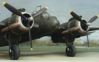
 The
engines seem to be inaccurately represented. The cooling fins on the cylinders of the
Bristol Hercules were much subtler than Tamiya's rendering. Also, the flame-damping
exhaust "bristles"’ are a little subdued. Looks like I’ll be able to
use some of that Falcon kit after all! Engine cowl flaps are moulded shut. All of these
shortcomings may now be addressed by various after-market engines, exhausts and cowl
flaps.
The
engines seem to be inaccurately represented. The cooling fins on the cylinders of the
Bristol Hercules were much subtler than Tamiya's rendering. Also, the flame-damping
exhaust "bristles"’ are a little subdued. Looks like I’ll be able to
use some of that Falcon kit after all! Engine cowl flaps are moulded shut. All of these
shortcomings may now be addressed by various after-market engines, exhausts and cowl
flaps.
Curiously, the engine cowling is attached to the sprue by three stout connectors on the side of the cowl ring! These were tricky to remove without blemishing the surface of the plastic.
The only modification I made to this area was to drill out the two small intakes at the
front of each exhaust fairing.
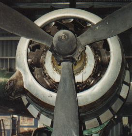
| Note the almost invisible cooling ribs on the
engine cylinders and the light, alloy-coloured cowl ring and cowl flaps (photograph of
restored Beaufighter at Camden Aviation Museum). B. Green |
The Vickers K gun for the framed rear-canopy option is oversimplified and could do with replacement or enhancement. It will be pretty obvious in the clear rear blister. Fortunately, my Aussie Mk. 21 did not require this option. The clear navigator’s blister fitted perfectly.
The DF loops inside the clear fairing on the upper-forward fuselage could be better represented by fine strip brass, but I used the kit parts.
Approaching final assembly, I attached the standard short nosecone and the bulged
housing for the Sperry autopilot. This fairing is unique to Australian Mk. 21
Beaufighters, and is not mentioned in the instructions.1 had to use a wipe of putty to
fair-in the auto-pilot housing.
Painting and Decalling
There is not a great deal of variety in the finish of Australian Mk 21 Beaufighters. Apart from the occasional post-war black and yellow "target tug" the camouflage was a uniform dark green. There is some controversy about whether this colour was RAAF Dark Green, allegedly a black-green shade close to the Luftwaffe RLM 70, or the commonly used RAAF Foliage Green, which was a much lighter hue.
I used a shade somewhere in between to represent a faded RAAF Dark Green. I sprayed a base coat of Tamiya XF-13 JA Green, and used a thinned black mixture to highlight panel lines.
I used the excellent Tamiya Colour Spray (Can AS-1: Bare Metal Silver) for the forward
cowl and cowl flaps, and Humbrol Copper for the rear engine cowl ring.
Weathering consisted of painting chipped wing walkways, rivets, fairings and leading edges
using a fine brush and Tamiya Enamel Chrome Silver. The key to success with this technique
is not to go overboard, be subtle. Red circles were painted over the wing gun ports to
represent doped covers.
 I used Ventura Decals sheet V4872 for the markings. This sheet should still be
available in specialist shops, although there are no shortage of new decals for this
popular subject from Aeromaster and Cutting Edge. Aircraft serials are not included with
this sheet so I used grey serials from Ventura sheet V4853. Decals conformed well over a
preparatory gloss coat, although the individually-cut serial numbers suffered from a
little silvering.
I used Ventura Decals sheet V4872 for the markings. This sheet should still be
available in specialist shops, although there are no shortage of new decals for this
popular subject from Aeromaster and Cutting Edge. Aircraft serials are not included with
this sheet so I used grey serials from Ventura sheet V4853. Decals conformed well over a
preparatory gloss coat, although the individually-cut serial numbers suffered from a
little silvering.
Conclusion
It is sometimes difficult when writing a review to accentuate the positive. My impression on opening the box was sheer joy; and my joy has not diminished after building the kit. This is another first class effort by Tamiya - the parts breakdown is simple, the construction sequence is modeller friendly while the internal and external detail is uncompromised.
Can improvements be made? Sure. But I was more than happy to build this one pretty much straight from the box. My biggest problem building my next Beaufighter will be the choice between using the Cutting Edge or the KMC resin detailing sets!
Reference
"RAAF Camouflage and Markings 1939-45 Vol 2" by Geoffrey Pentland, Kookaburra Technical Publications, Melbourne Australia, 1989. ISBN 0-85880-037-3
Back to HyperScale Main Page
Back to Features Page