Home
| What's New |
Features |
Gallery |
Reviews |
Reference |
Forum |
Search
Home
| What's New |
Features |
Gallery |
Reviews |
Reference |
Forum |
Search
|
|
|
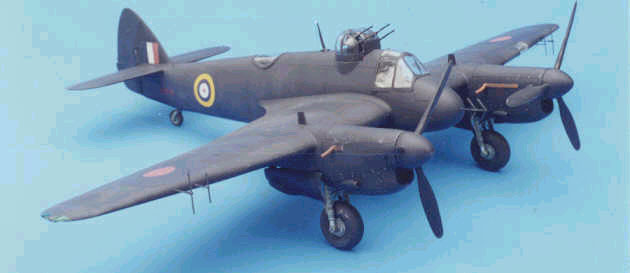
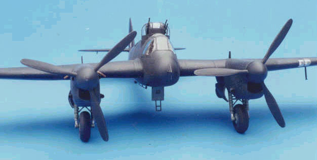
Bristol Beaufighter Mk. V by Dave Schemel
For some unknown reason the British seemed to love to fit nearly useless turrets into perfectly good fighter aircraft. In 1941 two of the already poorly performing Beaufighter MK II f s had drag inducing Boulton-Paul turrets installed and were designated Beaufighter MK V. The butt-ugly turret, with four .303 machineguns, replaced all of the wing armament and 2 of the fuselage 20 mm cannon. Both Mk Vs were tested operationally. The subject of my model number R2274 went to 406th squadron (RCAF), the other plane number R2306 went to 600th squadron and was destroyed in an accident on September 29, 1941. The Beaufighter MK V proved to be an all around failure.
I happen to like the pugnacious lines of the Beaufighter. I don't think the Merlin engined variants are nearly as attractive as the radial engined ones. Add that turret and you have one ugly plane. I just had to do it. It sure is different than the graceful Spits, 'Stangs and Doras I already have built.
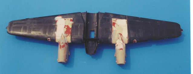
The basic kit used for this conversion was the Tamiya Beaufighter MK VI night fighter. I believe the plastic is the same as the rest of the Beaufighter Mk VI kits from Tamiya except that it is molded in a yucky, black plastic. There are enough reviews of this kit on the net that I will not do an in depth review here. I like the kit and think it has few faults worth worrying about. It practically falls together. I used a CMK Beaufighter Mk II f conversion as the beginning of this conversion. When my CMK conversion arrived I was pretty impressed. The instructions were a bit vague but real men don't need instructions. Tony Oliver gives us a close look at this conversion set in his "in-box" review here on Hyperscale. For clarity's sake, I will attempt to use the same names for the parts that Tony did. The resin casting was flawless but the packaging left a lot to be desired. A couple of small landing gear parts were damaged but nothing I couldn't get over. I started by cutting the casting blocks from the four big chunks of resin. I then test fitted the Merlin XX engine nacelles to the engine to wing fairing and found the nacelle was .030 inches wider than the mating surface on the wing fairing. I would have to fair it in to make it look right but again nothing I couldn't get over.
Next was it was time to cut huge chunks out of the wings to accept the wing to engine fairing and glue the kit wings together. I got lucky the first time and cut the wings in the right places. The overall fit of the engine wing fairing to the wing was not too bad except for the top of the wing. The outboard, rear corner of the resin part was about .060 inches low, with the adjacent sides tapering down to this point. I measured the wing and found that the plastic was in the right place but the resin pieces were wrong. Both wings were the same. I decided to glue them in and fill. Again it was nothing I couldn't get over but I was getting angry. Since I was going to be doing such heavy bodywork on the top of the wing I figured I might as well attach the engines too. I glued the engines to the wing to engine fairing. After the glue set I drilled a hole from behind the spinner location through engine and into the engine to wing fairing. I then glued in a piece of brass tube for strength.
I experimented with several putties during this project. The one I found most useful was an auto body shop putty called Icing by US Chemical and Plastics. This is a two-part putty similar to "Bondo" but thinner and smoother. It is harder than what we as hobbyists are used to but softer than most auto body products. It hardens quickly and within a few minutes you can sand or file to your hearts content. I spent a lot of time working on this wing getting everything as close to right as I could, backtracking several times once removing most of the filler (read: learning experience). Instead of using the blanks for the wing leading edge intakes, I chose to remove the intakes at the leading edge and fill with epoxy putty. I think using the kit-supplied blanks probably would have been a better choice. As Tony said the spinners are slightly oversize but after all this bodywork they were an easy fix. My propellers were well cast and not warped. I hollowed out the rear of the radiator and installed cooling flaps made from aluminum litho plate. I removed the large scoops on the side of the engines. I then made a more accurate replacement and cast four copies.
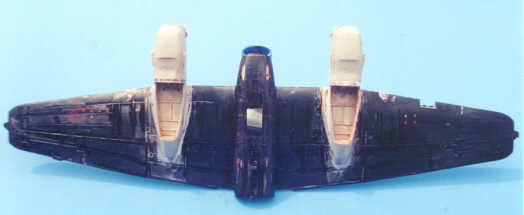
If I would do this again (fat chance) I think I would cut the wing engine fairing front to back horizontally to separate the top wing surface and the bottom wing surface/wheel well and glue them in at the right heights. I would also find a way to reinforce the joint of the plastic wing to the resin wing to engine faring. This joint is just a butt joint and broke on me more than once. The next big step was to modify the fuselage for the turret. I first turned a 7/8th inch thin wall tube out of acrylic on my Taig lathe this would be my fairing/turret race. I temporarily glued the fuselage halves together and then cut an appropriately sized hole using files, sanding drums and sand paper to get the right size and shape opening, checking often with the acrylic turret race. I then glued and filled the turret race to the fuselage. After installation I cut the turret race at the fuselage seam and separated the fuselage halves. The Mk V had one pair of 20 mm cannon removed from the fuselage. I have no idea which ones. I chose to remove the center pair of guns, their shell ejection chutes and the rear ammo boxes. Why I took out the rear ammo boxes is a mystery to me you can't even see them. I even repaired the floor where I removed the ammo box. At this point I was ready for some easy work. I used a Cutting Edge Beaufighter MK VI update set to improve the interior. The MK V Beaufighter was a retro fit from the MK VI and had the same cockpit as the later variant. That's my story and I am sticking to it 8^). Actually, I am sure that there were differences but I have no idea what they are and it looks better with the Cutting Edge cockpit than with the kit parts. Instead of a bubble-type canopy the rear cockpit was faired over with Perspex. I replicated it with overhead transparency material cut to shape. Plan A did not call for a painted edge to this part but when I glued it to the fuselage I had shiny spots under the clear plastic so Plan B (there is always a plan B) was put into effect. I masked off the edge of the Perspex and painted it to match the fuselage. I have no idea what the rear fuselage crew compartment looked like so I used the parts from the Cutting Edge kit and came up with something that looks right to me. The CMK horizontal tails are too long. I used the Cutting Edge horizontal tail to avoid having to fix this. This is a heavy model, we were joking that I would need to add lead to the rear fuselage to keep the nose down. I was a bit nervous about using the resin landing gear I was afraid that the landing gear would bend or break. I wound up modifying the kit parts and gluing them into the resin wheel wells. Last thing I built was the turret, which I thoroughly enjoyed. The only turret parts I did not scratch build were the guns, which I robbed from my Classic Airframes Defiant kit and some PE ammo belt sections from a True Details set. I vacuformed the clear parts over an acrylic master turned and polished on my lathe. Internet Modeler has a nice detailing article about the CA Defiant complete with scale drawings of the turret by David Batt. The address for this article is: http://internetmodeler.com/oct98/defiant.htm.
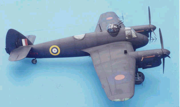
I knew from the onset that the paint job would make or break this model. I posted on Plane Talking to get suggestions on painting black aircraft. I made some test pieces from people's suggestions and decided to go with dark gray for the base color, even darker gray to post shade the panel lines use pure black for the panel lines and, to give it a little more life, not quite matt finish. I usually use pencil to darken panel lines but on a "black" airplane that would be too light. I tried black watercolor pencil and that seemed to work ok but I wasn't real happy with it. I then picked up a black gel roller pen and tried it. I like how it worked (writes nice too) so I drew in the panel lines with this.
I used Model Master enamel paints mixed for the dark grays. Flouquil Crystal-Cote and Testors Dull Coat were used for the topcoats. Decals were from an Aeromaster sheet and dry transfers were used for the serial numbers.
Many HyperScalers gave me input to the research, construction and painting of this model. Many other people from around the world e-mailed me to tell me they had the same fit problems with this conversion set. These people did wonders for my ego; I realized I didn't goof this thing up. I am sure I will forget someone if I attempt to name them, so I will just say thanks once again to all of you. Bob Katrosits took the pictures. Text Copyright © 2000 by Dave
Schemel
|