Home
| What's New |
Features |
Gallery |
Reviews |
Reference |
Forum |
Search
Home
| What's New |
Features |
Gallery |
Reviews |
Reference |
Forum |
Search
|
|
|
Messerschmitt Bf 109F-4 by Jerry Boucher
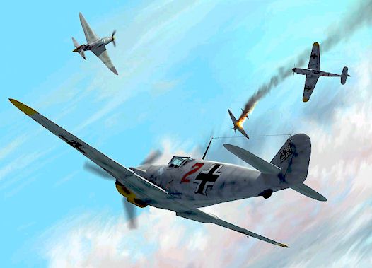
The images in this article depict a Messerschmitt Bf 109F-4 that I created using Autodesk's 3DS Max (v2.5) software and Adobe Photoshop. 3DS Max is a quite powerful computer modelling tool, whilst Photoshop is an excellent art software package which I used to make the paint-scheme and the background for my 'action' image. The basic premise for making this model was not for stunning physical accuracy (as such detail levels would soon seize up my humble PIII 450), but to create a realistic looking model that I could use in rendered 'action' scenes for my website.
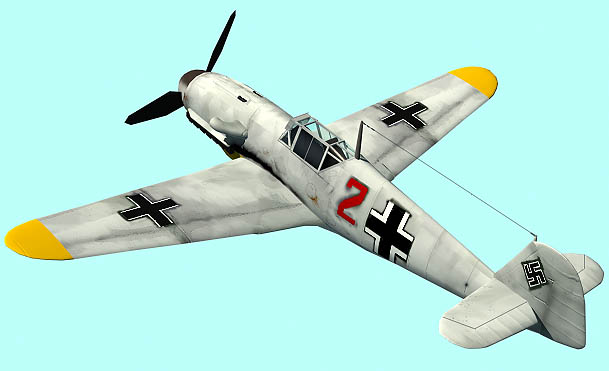
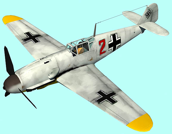
The Bf 109F-4 shown is from 5./JG5, a Jagdgeschwader that was based in Norway and Finland. It is finished in a rough distemper wash, typical of one of the various winter styles this unit employed.
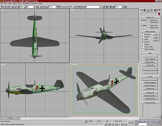
3DS Max allows the user to create and model a wide variety of shapes in various ways, but to create my model I used a technique whereby I manipulated basic geometric shapes (in this case, boxes, cylinders and spheres) that are 'pre-formed' by the software. In order to make the shapes that you want, you have to use a certain amount of lateral thinking and skull sweat to envisage the amount of detail you think you will need. So, in this case, I took a basic 24-sided cylinder and imagined how many sections along its' length I would need in order to define it's shape. This process is the same for the creation of many of the planes' different parts, the only difference being in the basic geometric object I start with.
Most of the manipulation is done at a vertex level - so in this instance, the different sections along the cylinder can be stretched, moved and scaled in order to created the basic shape of the aircraft's fuselage (Fig.1 to the left shows a basic cylinder before and after basic vertex manipulation). Another part of the modelling process includes the cutting into and out of certain areas, a process known as a Boolean Operation. This procedure is sort of like using a cookie cutter, whereby you can use one shape to cut out or make an impression in another. The cockpit area was where 2 Booleans were made - one to define the actual shape this area made in the fuselage and one that made a hole where the pilot would be seated
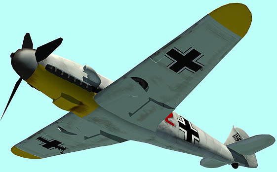
The most difficult Boolean was made when I was defining the troughs on the top of the nose for the MG17s, but after some trial and error (and some patching up with other objects to smooth out the definition of the area), I got the visual result I wanted. To make ailerons and other control surfaces on the wings, I selected certain faces from the wing shape and detached them. They then became separate objects, which could move independently, but retain the shape they had when they were part of the main wing's geometry. The cockpit frame and glass were simply thin rectangular boxes.
Once I had made all the basic shapes I wanted and placed them into the right position, my 109 looked like a basic unpainted model. The next step was to apply the virtual paint, or 'texture'. In order for this texture to be applied to my objects, they had to be 'mapped' first. This is a process that involved me actually taking the model apart again before carrying out the mapping process. The process I used was one of the most simple - 'planar mapping'. This is similar to applying a large blank virtual decal to the pieces of my objects. I then render a picture of these pieces, which is like taking a snapshot picture of them. The mapping co-ordinates that 3DS Max uses in this type of planar mapping are at the same ratio to the rendered picture, and I use this picture as the basis for the texture that will be applied to the pieces. So, if I opened the file of this picture in Photoshop, painted a big red X on the picture over the pieces, then saved this and assigned it to the pieces in 3DS Max, they would have this mark 'painted' on them over exactly the same areas.
The glass sections did not have to go through this process - 3DS Max can make any objects like glass if you adjust the opacity setting of any given texture. I just assigned the glass pieces a blank, blue-tinted texture and adjusted this opacity setting. Once I had the shapes rendered, I then painted over them in Photoshop with the right colours, and also painted on such details as oil streaks, panel lines and other markings. Photoshop has some great special effects filters that you can apply to an image that allow you to roughen it up, so that it almost looks weathered. You can also have an image which is made up of layers, with each layer containing different details, and you can also rub out or change the opacity of areas of one layer to let one beneath show through. I actually had one layer painted in a rough camo scheme, over which I placed another layer with the distemper colours, then just lowered the opacity of this layer to mimic the old camo showing very faintly through the distemper wash.
Now that my Bf 109F was ready, I made a copy of it and put both planes into another file in which I had two Yak-1 models. These Yaks were a much simpler design, but were meant to be seen in the distance and so required less detail. 3DS Max can create virtual cameras and lights that are very good at mimicking those in reality.
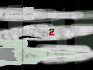
I placed a "camera" in a position to show a dynamic pose, and also placed 2 lights in the scene, one to simulate the light from the sun, and one to simulate reflected ambient light from the surrounding 'world'. I moved the models around in this environment until I had a picture that looked right and was lit nicely. I then rendered this scene as an image with a pale blue background. I then opened this image in Photoshop, and painted on details including the clouds, flames and smoke. The props were blurred using a blur special effects filter. This 'painting' is the most fun part of the whole process, as it brings everything to life. Once I had everything looking just right, I had the image that you see now. I plan to make a series of different scenes featuring this 109F, and 3DS Max has some very good environmental special effects that will allow me to put the plane in a scene with snow falling, or with fog, etc. I can also easily change the camo scheme to that of a different season, or add the personal emblems of a specific pilot or Staffel. As I'm also the C/O of an on-line squadron that play the flightsim 'European Air War', I can use the model to render a side-view that will show the personal markings of each virtual pilot.
I've tried to keep the descriptions above as lucid as possible without lapsing into jargon. All techniques that I've described are virtual, whereby all of the processes took place using a PC and its' software.
Model, Images and Article Copyright
© 2000 by Jerry Boucher Back to HyperScale Main Page Back to Features Page |
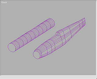 These 'wireframe'
objects actually made up of two elements that I can manipulate: faces (the
'flat' areas between each section of wire), and vertices (small points which
hold the wire together).
These 'wireframe'
objects actually made up of two elements that I can manipulate: faces (the
'flat' areas between each section of wire), and vertices (small points which
hold the wire together). 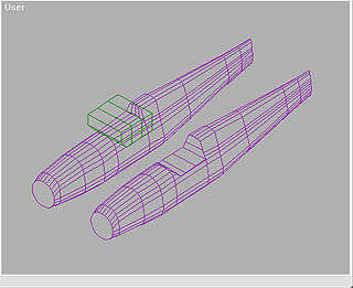 Figure
2 shows the fuselage and the Boolean shape to be cut out. The result of the
finished operation is on the right.
Figure
2 shows the fuselage and the Boolean shape to be cut out. The result of the
finished operation is on the right.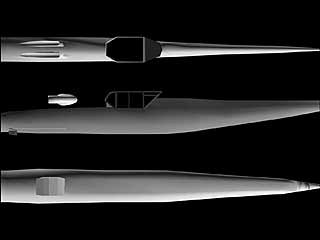 Creating
a uniform texture is easy for flat objects such as the wing and tail surfaces.
In order to get things looking right on the main fuselage, the upper and lower
surfaces of this piece have to be temporarily detached and rotated 90 degrees so
that they are mapped flat. If I did not do this, these upper and lower areas
would come out streaked and messy. (This is because this sort of planar mapping
effect is sort of like having a square projector light facing the objects and
passing it's 'beam' through them. It doesn't work so well when being projected
across rounded surfaces that are facing away from this 'beam'). Again, if I
render a picture of these parts, I can use this as a basis for the fuselage
texture.
Creating
a uniform texture is easy for flat objects such as the wing and tail surfaces.
In order to get things looking right on the main fuselage, the upper and lower
surfaces of this piece have to be temporarily detached and rotated 90 degrees so
that they are mapped flat. If I did not do this, these upper and lower areas
would come out streaked and messy. (This is because this sort of planar mapping
effect is sort of like having a square projector light facing the objects and
passing it's 'beam' through them. It doesn't work so well when being projected
across rounded surfaces that are facing away from this 'beam'). Again, if I
render a picture of these parts, I can use this as a basis for the fuselage
texture.