Home
| What's New |
Features |
Gallery |
Reviews |
Reference |
Forum |
Search
Home
| What's New |
Features |
Gallery |
Reviews |
Reference |
Forum |
Search
|
|
|
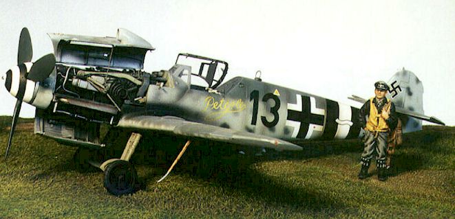
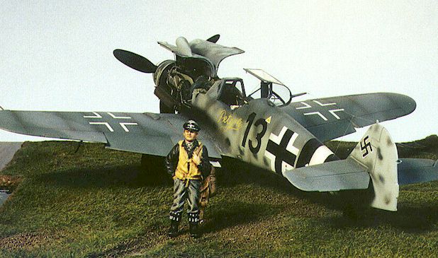
Messerschmitt Bf 109G-14/AS by
Floyd S. Werner, Jr.
When Aeromaster (High Tech) came out with their detail sets for the DB605A and D I was slightly disappointed, as only the top of the engine was fully detailed. However, when I was recently deployed during Operation Joint Endeavor in Bosnia I was able to take R+R in Budapest. After walking the streets for a little while I found the model magazine "Modell es Makett" (I try to keep up with modeling while deployed). Inside it had a beautiful 109G-10 with the engine displayed. I translated the article as best I could and determined that it was a kit and was available. Naturally I looked for the local hobby shop. I found it, and my Nirvana with it. I showed the clerk the magazine and promptly bought three of the sets. The price in Budapest was about $18.00. I believe the suggested retail in the States is around $35. The only reason I didn't buy more was because they didn't have any more.
When I visit foreign countries I always bring some photos of my models. It is a natural way to break the language barrier. Whenever possible I try to deploy with a model and some supplies to keep my mind off of getting shot at or the unknown. With the language barrier broken the clerk called some friends including one that spoke English. We talked modeling for about four hours. It is great to know that modeling is universal.
But back to the detail set. My samples were bubble free and nicely detailed. I didn't expect such a great kit from Hungary. I know that it sounds arrogant and predetermined. I was ignorant of the quality of work outside of "western civilization". I won't make the same mistake again. The kit contained 32 finely cast resin parts. It includes everything that you will need to cut the nose off the Fujimi kit and make a great looking 109. FM Details also fixes many of the inherent problems of the Fujimi kits. It lengthens the nose appropriately and it fixes the wing roots and flaps.
My first advice regarding this detail set is dry fit, dry fit and dry fit. Build the cockpit assembly per FM's instructions. I added some Eduard photo etched parts to the FM set. I know this makes for an even more expensive model, but I really wanted the ultimate Bf 109 in my collection. In my opinion, the interior has a better scale appearance than either Cooper Details or Teknics. The FM set provides you with throttle quadrant, gun sight, MW 50 panel, circuit breaker panel, oxygen regulator, vents, cockpit floor and seat. Everything went together great. A base coat of RLM 66 with a wash of black and a dry brush of light ghost grey brought out the detail. The oxygen regulator was painted RLM 24. Now is a good time to paint the instrument panel but don't install it yet. The kit utilizes the Fujimi instrument panel. The instruments were painted black and details were picked out with white. Construction of the fuselage is straightforward except for the cowl bulges. I found it easier to cut the panels before attaching them to the fuselage halves. You will also have to cut the oil cooler from the fuselage. I cut it off after assembling the fuselage to get a straight cut. Now that you separated the bulges attach them to the side with liquid cement. The directions are a little vague about attaching the wings so I did it at this point. Big mistake. If you turn the instructions over there is a filler plug to install in the wing root to fix the flap problem in the Fujimi kit. If you remember to put the plug in then now is a good time to thin the leading edge of the fuselage and wing. This area will be invisible after assemble so it doesn't have to be perfect. Thinning allows you to add the plumbing later in the construction. Now is a good time to add all flaps and slats. Install the gun trough assemble (FM Part 22) and gun deck (Part 23). These will require some filler. There were two solenoids on the gun deck and they were in the way so I cut them off and reattached them later. The instrument panel is now attached to the gun deck. I painted my forward area RLM 02, but they could be either RLM 66 or Aluminum. The MG 31s are supplied in three pieces. I added the aft portion of the guns now. I painted the initial camouflage after attaching the horizontal tail surfaces. You will have to decide which type of tail is for your aircraft. I cut the elevators and repositioned them (don't forget the cyclic). My camouflage consisted of RLM 74/75/76. I used Aeromaster colors that sprayed really well. The side mottle consisted of RLM 74/75/70/02.
Now comes the really long and laborious (read into that "fun") process of installing the engine. After cutting all the parts off their backing I started to test fit everything. And test fitting everything. And test, well you get the idea. The engine itself consists of 24 pieces including the engine bearers and individual exhaust stacks. I had to add the wiring for the ignition leads. Building the engine itself is pretty straightforward. Before attaching the oil tanks, exhaust stacks and engine bearers paint the engine assembly flat black. I dry brushed mine with silver and white in that order. Don't forget to add the engine designation (AS, A, or D) on top of the engine, normally in yellow. Now paint the oil tanks silver or RLM 02. The engine bearers are RLM 02 with the oil tank molded into the left one painted silver. I painted my exhaust stubs with Model Master Stainless Steel Buffable and then used orange pastels to attain the weathered and burnt effect. Drill the location holes for the exhausts now but don't install them until the end. Repeatedly dry fit the engine bearers through the shell exhaust discharge tubes. I found it easier to attach the engine bearers first and then fit the engine to them. This did bring up a problem in that to get an acceptable fit I had to cast the engine mounts and move them forward about 1mm. Otherwise, the engine appears to stick out too far. The next step is to install the lower engine bearer. Align them carefully, as any tiny error will manifest itself at the propeller thrust line. Be careful not to twist the engine in its mounts. It took a lot of pinning parts and dry fitting. Now with the engine hanging on the airframe I took a step back and admired the work so far. There still was no plumbing on the engine. After consulting my references I determined which lines I would represent. Using solder and wire brings the engine to life. The reason for using the solder is to prevent having to paint it, as well as, it is easy to mold. I added the landing gear and wheels. This has some psychological benefits. It also provides a way to elevate the new engine in preparation of putting on the cowlings. I had to drill holes for the oil cooler lines. Now came the biggest problem. The lower cowling, the whole thing that brings the engine to life, is about .050 too short. While this would be a really big problem when building a G10 or K4 it is nothing for an AS version. I did something that made building an AS so easy. I cut along the leading edge of the lower cowling. This did two things for me. The first was to give me a bulge to super glue to the front cowling. The second was to provide a straight panel to attach the extension to. I put .040 in the front part of the cowling and .010 on the aft portion. After fairing in the extensions another problem was identified. The lower cowling provided by FM utilizes the oil cooler from the kit; however, the opening in the cowling is too small. I built up the assembly with styrene and cut out the aft portion for the oil cooler door. I added the drain line for the front of the oil cooler. After looking at "Black 6" and "Black 2", I left a little repaired damage visible here as this seems to be a part that frequently breaks. The oil cooler door was fashioned from styrene, as was an actuator rod. I painted the inside of the cowling Model Master Steel and Magnesium. I needed to add the forward cowling, which includes the oil tank. Now I could attach the lower cowling. Before I did this I added the exhaust stacks. Now came some Eduard parts. I used the exhaust deflectors for both sides. After that I attached the lower cowling at the appropriate angle.
The upper cowlings are wonderful and detailed nicely. After looking through AeroDetails on the 109G I noticed the Finnish 109 had natural metal and RLM 02 panels. I decided to do one side this way and one all natural metal. I painted these panels on the outside at this time. I held off on attaching these cowlings until I finished the rest of the model. The rest of the model went together easily. The only other part from the FM set is the propeller hub and this easily fits with the kit backing plate.
That finished the model in a mere 200 hours of which only 150 hours were spent on the
engine area. I am quite happy with the outcome. This G14 adds a missing link in my
collection and just grabs your attention. I finally have an exposed engine of the huge
DB-605AS. The FM detail set is great, however, there are some shortcomings and scratchbuilding
experience is necessary. I recommend it to any 109 fanatic, but be ready for some work! It
is expensive in the States, but I feel it is worth the money.
Article, Model and Photographs Copyright © 1998 by Floyd Werner.
|