 Home
| What's New |
Features |
Gallery |
Reviews |
Reference |
Forum |
Search
Home
| What's New |
Features |
Gallery |
Reviews |
Reference |
Forum |
Search
|
|
|
Messerschmitt
Bf 109G-14/AS CONVERTING
REVELL'S by
Randy Lutz
I have had this original issue of the Revell Bf-109G for a number of years, but it just wasn't one of my pressing priorities to build it. This is the version that depicted the Gruppenkommander's aircraft of JG54 taking off from a snow covered field. It has a copyright date of 1969, which puts it in the range of 30 years old. I am not sure, but I think a kit of this vintage which has so many innovative features such as recessed scribing and operating parts as well as total inaccuracy should be considered a classic! It almost seems like an act of desecration to hack it up, but, I am a builder, not a collector. To be truthful, I would have never even considered attempting this conversion if it were not for a combination of circumstances that took place one night. We have a ritual in IPMS Ottawa where a small group of us will meet at someone's house for a "building session". The host usually supplies the beer and munchies and the activity will start between 7 and 8 pm. and has been known to finish close to sunrise. Needless to say, one tends to become a bit more adventurous after numerous bottles of beer and sleep deprivation and this is what happened to me about 2:30 am. I just decided that I wanted to build a late model 109 and dove in feet first. After the initial measuring and cutting there was no turning back. What follows is a process that took place over a period of 1 1/2 years as my interest would peak and than subside.
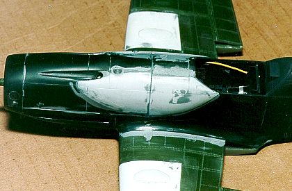
The underside of the kit nose has a large bump which does not appear on any
109's. To correct this, the inside of the fuselage was filled with Aluma-lite and then the
outside was filed to the correct shape. The Aluma-lite is necessary as the The supercharger intake must be modified as well. The AS versions of the 109 had a larger intake than the others in the "G" series. The first step is to shorten the overall length by cutting approximately 1/8" off the front. Then build up the body of the intake with either putty or a combination of styrene and putty to give it a fatter profile.
The last major step for the fuselage involved the cockpit tub. Very minor surgery is required for Revell kit parts 21,23 and 39. After that, you're on easy street. Eduard parts 25 and 26 are the cockpit sidewalls and once fastened to the floor, eliminate that see through look which has plagued this kit. The etched relief is well done and will show up well once the parts are given a dark wash and lighter dry-brushing. A must considering the entire cockpit area is to be painted RLM 66.
With the major conversion work complete, it was time to correct the wing bulges. The
wheel well bulges as supplied by Revell are grossly oversize and inaccurate and are
designed to accommodate the retractable undercarriage. My first To add a little more visual interest to the model, I cut away the top and bottom radiator flaps. These were then replaced with the corresponding Eduard pieces from the exterior detail set. I am very pleased with this area as it adds a more natural appearance to the finished model. The top and bottom halves of the wing were assembled, trapping the photo-etched radiator screens and landing gear struts. On the subject of the undercarriage, the mounting area must be modified to allow the gear legs to sit at the proper angle. This is best accomplished by deepening the rear mounting holes. The completed wing unit was fastened to the fuselage along with the modified tail planes. I found that the right hand wing required a thin strip of styrene to properly fill the gap at the wing root and even out the dihedral from side to side. Then came the enjoyable task of filling and sanding and then more filling and sanding. Once all the basic body work was completed, the model was given a few coats of Model Master primer, and any areas requiring further work were dealt with at this time. The cowl proved to be an area which required constant attention to get it just right. An OLFA "P" cutter was used to lightly scribe the new cowl panel lines, while the line delineating the rear of the engine cowl was made a little deeper and wider. Next the various jacking points, engine starter crank hole and flare pistol port were drilled out. To replicate the small scoops found on the nose, I sliced off small pieces of plastic tubing on a diagonal angle and glued them in place with a minute drop of liquid cement. The small bumps on the top of the cowl were made by slicing off the ends of some missiles from the Hasegawa 1/32 F-86 Sabre and gluing in place. Once dry, they are sanded to the proper contour. To effectively blend them in to the cowl, I applied Tamiya putty with my finger soaked in nail polish remover. The nail polish remover allows you to work the putty without it drying out while making it more liquid in nature. If done properly, minimal sanding is required once the putty dries. The windscreen was next to be installed, and for this I used the front section supplied by Revell. The Erla Haube portion of the canopy proved to be more difficult. I had an old Horizon vacuform canopy dating from the 1970s which I started to cut out. I had almost completed this when the rear of the canopy cracked. I didn't think that a vacuform canopy could crack, but then again we learn something new every day! I thought about using the canopy with the crack, but it would prove to be too visible. I then debated about using another vacuform canopy from the Avia S.199 produced by Roberts Model Parts, but it was the later blown style. Finally, a modelling buddy offered to vacuform a new canopy. We filled the cracked canopy with Alum-Lite and when dry, the canopy was removed from the Alum-Lite and the resin plug was then used as a master to vacuform a replacement. I have to admit that the new piece is superior to the old Horizon canopy. If you have ever had a canopy which did not have any framing indicated, you can appreciate how difficult it can be to mask off the framing with no lines to guide. Here's a tip I use when faced with this problem. Take a dark coloured tape which is fairly thick, I use a 3M #471 vinyl tape; it is similar to electrical tape but does not leave any residue. Cut it into thin strips the width of your framing and apply it to the canopy where you would want the framework. Then cover the entire canopy including the vinyl tape with masking tape. Using a sharp knife with light pressure you can follow along the coloured tape as it shows through the masking tape and cut away the framework. When you lift off the masking tape the coloured tape will come with it leaving a perfectly masked canopy.
I elected to fabricate new navigation lights with clear sprue. This is an easy modification that can be accomplished using Lite-Brite pegs, toothbrush handles or clear sprue, depending on the type of light you wish to portray. To represent the bulbs, I drilled out each piece of clear sprue and then placed a drop of green paint in one hole and red in the other. The lights were super-glued to the wing, sanded to shape and then polished with Blue Magic metal polish. After that, they were masked off in preparation for the later painting stage.
The Eduard photo-etched wheel well inserts were next to be installed. These consist of two parts for each opening. One is a flat piece that fastens to the underside of the top part of the wing. This does a good job of hiding the previous wheel bulge body work. The second piece must be rolled over a paint brush handle and then glued to the edges of the lower half of the wing. These two parts have beautiful detailing and come to life after being sprayed with Xtracolor X201 RLM 02 Grau and then given a dark wash and a little dry-brushing. After these photo-etched parts were installed, I lined the sides of the wheel wells using .005 thou styrene. To reproduce the leather liners, I airbrushed some decal film with Model Master Leather, and then using a dressmakers pattern wheel, I ran two parallel, but staggered lines of small perforations to represent the lacing grommets. The final step was to draw in the lacing by joining the perforations using a dark brown coloured pencil. This was then installed as a normal decal.
Prior to painting, smaller details such as the MW50 drain tube, fuel primer drain and the underwing antenna were added. Testors Model Master Insignia White (FS17875) was airbrushed on the rear fuselage. Once dry, the white segment of the Defence of the Reich band was masked off and then Model Master Gloss Black was applied. It was subsequently masked off in preparation for the camouflage. The first camouflage color to be applied was the RLM 76. For this I used Xtracolor X208, Lichtblau. This was airbrushed on the underside of the wings and the entire fuselage along with the drop tank and undercarriage doors. Xtracolor X206 RLM 74 Graugrun was then applied to the top of the fuselage and upper surface of the wings, followed by Xtracolor X207 RLM 75 Grauviolet. The fuselage mottling was applied using RLM 02, 70 and 74, all of which were Xtracolor. A few minor touch-ups with the RLM 76 and the painting was completed.
A mixture of Testors silver and Winsor and Newton Raw Umber oil paint was carefully applied with a 000 sable brush to represent the chipping and scuffing which would normally show on the actual aircraft. Note that the wing root chipping does not come in contact with the upper surface of the radiator flaps as it was strictly forbidden to walk on these parts of the 109. The chipping is heavier near the front of the right hand wing as opposed to the left, because this is where the ground crew would stand to insert the engine crank handle. With the chipping completed, the entire model was given a few coats of Floquil Flat, thinned with lacquer thinner. Before any pastels were applied, the exhaust staining was airbrushed using Xtracolor X504 Exhaust. This paint really does a fine job of capturing the true look of the exhaust residue. It dries to a black/brown shade and sprays beautifully if thinned considerably with lacquer thinner and shot at medium to low air pressure. Pastels were next, with all the panel lines on the undersurface being highlighted with a medium grey. The upper surfaces benefited from various shades of darker grey, while black was used to represent the cordite residue from the cowl guns.
The drop tank was installed using the Eduard mounting hardware and some steel rod to represent the sway braces. The FuG16ZY D/F loop was made from a leftover photo-etched steel fret, the underwing FuG16ZY Morane antenna is a section of Sutcliffe airfoil strut material and a piece of steel surgical wire, while the fuselage mounted FuG25a IFF antenna was made from piano wire. Prior to fastening the hinged section of the canopy, the Eduard photo-etched late model armoured headrest was assembled, with the clear glass section cut from scrap acetate and glued in place using white glue. The final steps consisted of a stretched sprue antenna wire and painting the pitot tip in brass. Overall, the entire process was not that difficult. The conversion steps were just a different way of correcting the kit's inaccuracies. However, it sure would be nice to have a 1/32 109 which is up to the standards that the 48th boys enjoy. Regardless of scale, a good Messerschmitt will sell! I had little information relating to Scheufele's military career and what follows is information found in Kookaburra's Planes of the Luftwaffe Fighter Aces, Vol. 1., also recently reprinted under the Schiffer label. After initially flying top cover for the German Navy, Scheufele moved East, serving with 2/JG5. Late in 1944, he was transferred to 14/JG4 as part of home defence under the command of Kommodore Michalski. Scheufele was shot down by American ground fire on December 3, 1944 with his total victory tally for the war amounting to 18, of which two were unconfirmed. Scheufele flew a Bf-109G-14/AS finished in an unconventional day fighter scheme of 74/75/76 with very distinct 02/74 and 70 mottling. His aircraft displayed JG4's black/white/black Defence of the Reich bands and the IV Gruppe marking. Painted in yellow under the cockpit was the name "Peterle", which was Scheufele's girlfriend at the time. When Scheufele was shot down he was flying his back-up aircraft, "Black 2", as "Black 13" was unservicable at that time. He ended the war as a POW in an English camp.
"The Last of the Eagles, A scale modeler's guide to the Messerschmitt Bf 109G and K", by John R. Beaman Jr. Model Art No. 290, Messerschmitt Bf 109G/K Augsburg Eagle, Model Art Company, Tokyo Japan Planes of the Luftwaffe Fighter Aces Vol. 1, Bernd Barbas, Kookaburra Technical Publications, Australia No. 57, Messerschmitt Bf 109 in Action, Part 2, Squadron Publications
Article, Model and Images Copyright © 1999 by Randy Lutz
|

 The first step
involved the refined cowl bulges, but to do this, the fuselage halves had to be assembled
and the engine cowl fastened in place. To get the basic shape of the bulges, I used
Beaman's Last of the Eagles as a guide by tracing the outline of the bulges onto paper and
then from the paper to sheet styrene. Each side of the cowl bulges is made from three
layers of .020 thou styrene laminated together. The first layer is slightly larger than
the second, which is then slightly larger than the third. This would facilitate the final
shaping and sanding. Prior to laminating the plastic together, the pieces were placed in
boiling water and shaped to follow the contours of the kit nose. The new bulges were glued
to the nose, and any gaps filled with super glue while Tamiya putty was used to blend in
everything. After much sanding and filling the cowl profile matched the template copies
from Beaman's book.
The first step
involved the refined cowl bulges, but to do this, the fuselage halves had to be assembled
and the engine cowl fastened in place. To get the basic shape of the bulges, I used
Beaman's Last of the Eagles as a guide by tracing the outline of the bulges onto paper and
then from the paper to sheet styrene. Each side of the cowl bulges is made from three
layers of .020 thou styrene laminated together. The first layer is slightly larger than
the second, which is then slightly larger than the third. This would facilitate the final
shaping and sanding. Prior to laminating the plastic together, the pieces were placed in
boiling water and shaped to follow the contours of the kit nose. The new bulges were glued
to the nose, and any gaps filled with super glue while Tamiya putty was used to blend in
everything. After much sanding and filling the cowl profile matched the template copies
from Beaman's book. 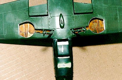 kit plastic is not thick
enough to allow for the amount of plastic that has to be removed. To complete the nose
area, the Revell oil cooler screen, (part 20) was replaced with photo-etched pieces from
the Eduard's excellent set number 32-014 which deals with the 109 exterior. Also used from
Eduard were the exhaust manifold shields. Eduard has done a fine job of representing these
pieces and has captured the asymmetrical look of the two parts.
kit plastic is not thick
enough to allow for the amount of plastic that has to be removed. To complete the nose
area, the Revell oil cooler screen, (part 20) was replaced with photo-etched pieces from
the Eduard's excellent set number 32-014 which deals with the 109 exterior. Also used from
Eduard were the exhaust manifold shields. Eduard has done a fine job of representing these
pieces and has captured the asymmetrical look of the two parts. 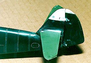 The next major
modification involved the vertical tail and stabilizers. Scheufele's G-14 had a tall tail
whereas Revell provides the earlier short style. In order to correct this, the top portion
was cut from the stock tail and replaced with laminated styrene which had a profile
matching the Beaman drawings. It should be mentioned that the Beaman publication provides
detailed plans in 1/32 scale as well as 1/72 and 1/48 scales. The new tail section was
filled and sanded and the rudder mass balance was added. I had added the two external trim
tabs as shown in the Kookaburra artwork, but further research in Beaman's book suggests
that the G-14/AS did not have these tabs. So as a result, they were removed. Next, the
horizontal stabilizers were modified by removing the non-scale hinge tabs and reshaping
the outline of the elevators. New trim tabs were made from .010 thou styrene and super
glued in place.
The next major
modification involved the vertical tail and stabilizers. Scheufele's G-14 had a tall tail
whereas Revell provides the earlier short style. In order to correct this, the top portion
was cut from the stock tail and replaced with laminated styrene which had a profile
matching the Beaman drawings. It should be mentioned that the Beaman publication provides
detailed plans in 1/32 scale as well as 1/72 and 1/48 scales. The new tail section was
filled and sanded and the rudder mass balance was added. I had added the two external trim
tabs as shown in the Kookaburra artwork, but further research in Beaman's book suggests
that the G-14/AS did not have these tabs. So as a result, they were removed. Next, the
horizontal stabilizers were modified by removing the non-scale hinge tabs and reshaping
the outline of the elevators. New trim tabs were made from .010 thou styrene and super
glued in place. The overall
design is well thought out, as the cockpit is built as a complete tub and can be installed
after the fuselage halves are assembled. As is usual with the new releases from Eduard, is
a complete set of seat belts. This saves you from having to purchase an additional
product. Eduard indicates which parts could be supplemented with the use of plastic stock,
but they do not tell what thickness should be used. I think that most builders, using a
little common sense, will be able to select a size which will be appropriate. The seat pan
proved to be the most difficult to bend as it requires a smooth curved shape as opposed to
a sharp bend. I used the handle from a Tamiya paint brush to arrive at a shape which would
line up with the sides. This set builds into a fine cockpit and can only be improved by
adding bits of plastic to some of the knobs and levers. Only two original Revell parts
remain in the cockpit, these being the floor, part 39 and the control column, part 37.
Everything else is supplied in the Eduard detail set for the interior. The only thing
missing from the Eduard cockpit set is the fuel line. For this I used a section yellow
telephone wire which was sectioned with a length of clear sprue near the instrument panel.
The cockpit tub was installed from underneath as a complete unit and is a significant
improvement over the stock parts. The fuselage will require some grinding on the inside in
the vicinity of the gun breech covers to allow the tub to be raised high enough.
The overall
design is well thought out, as the cockpit is built as a complete tub and can be installed
after the fuselage halves are assembled. As is usual with the new releases from Eduard, is
a complete set of seat belts. This saves you from having to purchase an additional
product. Eduard indicates which parts could be supplemented with the use of plastic stock,
but they do not tell what thickness should be used. I think that most builders, using a
little common sense, will be able to select a size which will be appropriate. The seat pan
proved to be the most difficult to bend as it requires a smooth curved shape as opposed to
a sharp bend. I used the handle from a Tamiya paint brush to arrive at a shape which would
line up with the sides. This set builds into a fine cockpit and can only be improved by
adding bits of plastic to some of the knobs and levers. Only two original Revell parts
remain in the cockpit, these being the floor, part 39 and the control column, part 37.
Everything else is supplied in the Eduard detail set for the interior. The only thing
missing from the Eduard cockpit set is the fuel line. For this I used a section yellow
telephone wire which was sectioned with a length of clear sprue near the instrument panel.
The cockpit tub was installed from underneath as a complete unit and is a significant
improvement over the stock parts. The fuselage will require some grinding on the inside in
the vicinity of the gun breech covers to allow the tub to be raised high enough. attempt at correcting
the bulges involved purchasing a set of vacuform replacement wing tops produced by Engines
and Things. When the parts arrived, I found that they were really not usable as they had a
multitude of small bumps on the surface and the panel and rivet detail varied from nice to
non-existent. Consequently, I elected to remove just a section of the wings and replace
with the corresponding area from the vacuform parts. With the new sections glued in place,
any panel and rivet detail lost during the sanding process was replaced using a scriber
and a hypodermic needle. The end of the needle is bevelled about its circumference and
then placed in a pin-vise. Gentle pressure with a slight twisting motion will reproduce
the small engraved circles (rivets).
attempt at correcting
the bulges involved purchasing a set of vacuform replacement wing tops produced by Engines
and Things. When the parts arrived, I found that they were really not usable as they had a
multitude of small bumps on the surface and the panel and rivet detail varied from nice to
non-existent. Consequently, I elected to remove just a section of the wings and replace
with the corresponding area from the vacuform parts. With the new sections glued in place,
any panel and rivet detail lost during the sanding process was replaced using a scriber
and a hypodermic needle. The end of the needle is bevelled about its circumference and
then placed in a pin-vise. Gentle pressure with a slight twisting motion will reproduce
the small engraved circles (rivets).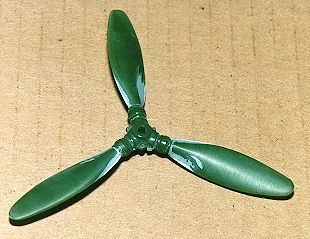 Another area
that required corrections was the propeller. To accurately portray the prop found on the
G-14/AS, the kit's blades must be shortened, material has to be added to increase the
width where the blades meet the hub and then reduce the width at the mid-way point of the
blades. Sounds fun doesn't it? The completed propeller was airbrushed RLM 70 using
Xtracolor X204. To complete this area, the spinner was airbrushed using Testors Model
Master Gloss Black, and once dry the spiral decal was added using the Superscale sheet
number 32-92,(109F-K data stencils).
Another area
that required corrections was the propeller. To accurately portray the prop found on the
G-14/AS, the kit's blades must be shortened, material has to be added to increase the
width where the blades meet the hub and then reduce the width at the mid-way point of the
blades. Sounds fun doesn't it? The completed propeller was airbrushed RLM 70 using
Xtracolor X204. To complete this area, the spinner was airbrushed using Testors Model
Master Gloss Black, and once dry the spiral decal was added using the Superscale sheet
number 32-92,(109F-K data stencils).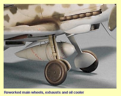 The G-14/AS was fitted with
the late model solid wheel hubs, not the spoked variety as found in the kit. This is a
simple fix that does not take too long to complete. I used an OLFA "Circle
Cutter" to cut out a new wheel disk from .005 thou styrene. It is then placed on a
pad of 3M Post-it notes and a circle template is set on top of the disk. Align the wheel
disk with a slightly smaller size hole in the template. Then using a ball point pen with
heavy pressure, draw a circle on the wheel disk. Once you turn over the disk you will have
a ridge around the outside, just in from the edge. This simulates the bevelled edge of the
original. I then used a Waldron punch and sheet styrene to reproduce the six small bolts
around the perimeter of the disk as well as the larger disk and hex nut in the centre. A
thin cross-section of plastic tubing was glued to the hub to represent the opening for the
tire valve. Next the entire wheel hub was painted gloss black and dry-brushed with a light
grey. This operation was then repeated for the other wheel. While on the subject of the
landing gear, I fabricated the leather dust boot for the tail wheel by soaking a small
amount of facial tissue in a mixture of white glue and water. It was then wrapped around
the tail wheel strut and worked to produce a few folds and wrinkles. When dry, it was
painted leather and dry-brushed with a lighter brown. All tires were finished in Testors
Rubber from the Pla line of paints.
The G-14/AS was fitted with
the late model solid wheel hubs, not the spoked variety as found in the kit. This is a
simple fix that does not take too long to complete. I used an OLFA "Circle
Cutter" to cut out a new wheel disk from .005 thou styrene. It is then placed on a
pad of 3M Post-it notes and a circle template is set on top of the disk. Align the wheel
disk with a slightly smaller size hole in the template. Then using a ball point pen with
heavy pressure, draw a circle on the wheel disk. Once you turn over the disk you will have
a ridge around the outside, just in from the edge. This simulates the bevelled edge of the
original. I then used a Waldron punch and sheet styrene to reproduce the six small bolts
around the perimeter of the disk as well as the larger disk and hex nut in the centre. A
thin cross-section of plastic tubing was glued to the hub to represent the opening for the
tire valve. Next the entire wheel hub was painted gloss black and dry-brushed with a light
grey. This operation was then repeated for the other wheel. While on the subject of the
landing gear, I fabricated the leather dust boot for the tail wheel by soaking a small
amount of facial tissue in a mixture of white glue and water. It was then wrapped around
the tail wheel strut and worked to produce a few folds and wrinkles. When dry, it was
painted leather and dry-brushed with a lighter brown. All tires were finished in Testors
Rubber from the Pla line of paints.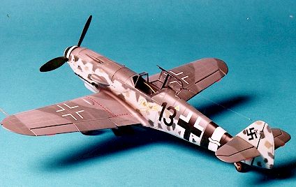 The decals were
next to be applied, and for Scheufele's aircraft I used the Ventura sheet number V3251.
All decals went on without any problems, but be advised, while these decals from Ventura
are very thin, they are not opaque and will tear easily if moved too much. The Ventura
decals do produce a milky residue when applied, but it does wipe away with a damp cloth
after the decals have dried. All the stencilling and smaller decals came from the
Superscale sheet previously referenced. If you elect to use these stencils, pay attention
to which variant of the 109 you are building as there are different fuel octane triangles
and not all stencils are common to all versions. Solvaset is my decal setting solution of
choice, and worked equally well on both brands of decals.
The decals were
next to be applied, and for Scheufele's aircraft I used the Ventura sheet number V3251.
All decals went on without any problems, but be advised, while these decals from Ventura
are very thin, they are not opaque and will tear easily if moved too much. The Ventura
decals do produce a milky residue when applied, but it does wipe away with a damp cloth
after the decals have dried. All the stencilling and smaller decals came from the
Superscale sheet previously referenced. If you elect to use these stencils, pay attention
to which variant of the 109 you are building as there are different fuel octane triangles
and not all stencils are common to all versions. Solvaset is my decal setting solution of
choice, and worked equally well on both brands of decals.