 Home
| What's New |
Features |
Gallery |
Reviews |
Reference |
Forum |
Search
Home
| What's New |
Features |
Gallery |
Reviews |
Reference |
Forum |
Search
|
|
|
CA-13
Boomerang
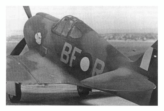
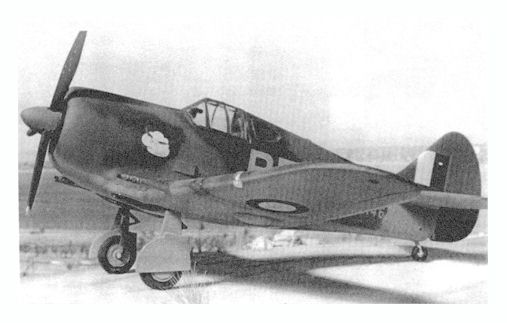
I wrote this article in 1996 during my stint as Editor of IPMS NSW "News and Views" magazine. Since writing the article I have also learnt that the position of the LTD cockpit opening in the fuselage is incorrect. There are only two images due to the limitations of the original photocopied magazine format. The original photos were black-and-white, and they were processed as dot-screens to maximise their reproduction in the magazine. The subject matter didn't help much either. Our local IPMS club photographer suggested that the model looked "like a potato", due presumably to its flat low contrast finish and its stumpy design! I have therefore reprocessed the images to depict black and white snapshots. Better than nothing I suppose...
The Commonwealth Aircraft Factory Boomerang was a remarkable little aeroplane. It achieved an incredibly short tunaround from concept to production due to the critical nature of the Australia's tactical position and the lack of an effective defensive fighter force. Despite the speed of development, more suitable aircraft had been scrounged from American sources by the time Australian forces met with Japanese aircraft over the skies of Darwin and New Guinea. The Boomerang undoubtedly represented a great achievement for Australia's fledgling aeronautical industry; and proved its ruggedness in its eventual role of Army Co-operation and reconnaissance. However, it was not significant in terms of numbers built nor by any unique contribution to victory. So why are so many model manufacturers interested in this stumpy little aeroplane?
LTD is at least the fourth company to release a Boomerang in 1/48 scale. Curiously, none of the four Boomerang kit manufactures are Australian! The first kit was a very limited run resin offering consisting of about fifteen pieces. The kit was so limited that, in common with many Eastern European kits of around ten years ago, it included no company identification or instructions. The fuselage was a one piece solid resin affair with a hole representing the cockpit. The horizontal and vertical tailplanes were cast as a single assembly, with a separate rudder completing the assembly. Each wing was a similarly simple one-piece casting. The remaining pieces represented wing cannon, undercarriage and a few basic cockpit details. Despite its simple construction and basic cockpit, the result was a good representation of the original aircraft with finely wrought surface detail. It was also impressively heavy, a fact well catered for by the kit's steel-reinforced undercarriage legs! The second Boomerang attempt also sprung from Eastern Europe. This time NKR Resin took the credit as manufacturer. The construction breakdown was more like a conventional plastic kit, with separately cast fuselage and wing halves. However, the quality of the disturbing flesh coloured resin was appalling - feeling soapy to the touch yet being unreasonably brittle to work with. My example was also badly warped. This kit may still be available, but should be avoided if possible! The third Boomerang at least came from the Southern Hemisphere! Ventura of New Zealand produced this injection moulded styrene kit. Thick sprue gates are to be expected on a limited run kit such as this - and we are not disappointed. However, there must be a solution to the thick, raised channel lines on the inside surfaces of all major pieces. The removal of these are essential for correct part's alignment, but it is a time consuming and frustrating task. Some members may have read the terrible bagging this kit came in for when reviewed by Scale Aviation Modeller in 1996. Having seen the kit, I am sure it was justified! However, in the interests of having something nice to say about the model, the interior detail and the engine are very nice, and a more recent review in Scale Aircraft Modelling suggests that the kit is really no more difficult than your average limited run injection moulded kit.
The most recent entry to the apparently crowded Boomerang market is the LTD CA-13/19. Moulded in Europe and marketed from the USA, this is really the first Boomerang kit to be widely available to the general modelling community.
However, on the positive side, the engraved panel lines and rivet details are nicely done and there are no heavy channels to remove from the inner surface of parts. The cockpit canopy and rear armoured glass are good quality vacforms. A spare canopy is provided - a sensible precaution against hamfisted scalpel-wielders like myself. The vacform parts are separately bagged. The exhaust stack, comprising of dozens of porcupine-like bristles, is a lovely resin casting. This is also supplied in a separate bag. Strangely, the instructions make no mention of this assembly, which should be attached with super glue to the recess on the starboard fuselage half. Decal options are provided for three aircraft - two overall foliage green and one disruptive green/brown/sky blue. The quality of the decals, printed by ScaleMaster, is excellent. Alternative markings are catered for by Aeromaster's after-market Boomerang decal sheets. The contents of the now familiar LTD box are completed by a set of well-illustrated instructions. Despite the absence of part numbers, the modeller will be assisted by descriptions of parts. Features of the kit include a nicely detailed engine, optional bulged tyres and auxiliary belly mounted fuel tank. In the box, the LTD kit certainly looks like the best attempt yet at a 1/48 scale Boomerang. But how does it hang together?
It was my intention to build this kit, as far as possible, out of the box.
Parts Removal and Cleanup It is essential to spend a little extra time on cleanup and preparation of parts when building a limited run kit. I commenced by cutting the parts from their sprues. Do not use your favourite pair of nail scissors for this job - the sprue connecting points are too thick. I used a saw blade in a hobby knife handle, and cut the sprue well away from each kit part. I then removed the remaining waste with a new knife blade. The major areas of flash were cleaned up with the same knife. Take care not to remove the locating tabs on the inner edge of the upper wings and the outer edges of the lower middle wing section. (They look a lot like flash!) Minor ragged flash circumnavigated most of the major pieces. This was quickly sanded with a small "wet and dry" sandpaper block (used wet). The same block was used to smooth the mating surfaces of all major parts to help ensure a flat surface for joining. I then turned my attention to the surface quality of the major components. Some of the parts had a rough, sandpapery feel to the surface. I sanded all wing and fuselage components with 1000 wet and dry, and polished the pieces with Gunze's "Mr Rubbing Compound". This process resulted in a shiny smooth finish, but did not interfere with the finely engraved panel lines. The final step in preparing the parts was dry fitting the major components. Fuselage and wing components were taped together, and apart from some excessive dihedral on the port outer wing, the fit looked good. This extra preparation time took only around one hour.
Cockpit The Boomerang cockpit was not a "tub" but a tubular steel frame on which were mounted various bits and pieces which make the average cockpit look like such a busy place. There was no floor as such. There were skid plates (one per foot) which were mounted below and aft of the rudder pedals. The seat was mounted on an armour plated bulkhead at the rear of the cockpit. This complex structure of tubular steel, fuselage framing, actuator rods, wiring and instrumentation is somewhat oversimplified in this kit. An attempt is made to represent the tube steel by a moulding on the inner surface of each fuselage half. Rudimentary floor, rudder pedals, joystick and instrument panel are supplied. The seat and its associated bulkheads are really quite nice. I first turned my attention to the instrument panel. This was painted Aluminium using Testors "Metalliser" series, then oversprayed with acrylic black. I then used a sharp scribing tool to scratch dial and figure details on the recessed instruments. The panel was drybrushed in dark grey to create a slight contrast between the instruments and their surrounding panel. Although the simple detail did not include switches and knobs, these were represented by white, yellow and red paint. Finally, I mixed up a batch of 5 Minute Araldite and carefully dropped blobs into each instrument recess to represent the lenses. Following the construction and painting of the other cockpit components, the entire subasembly was put to one side.
Engine The engine is a two piece affair (one piece per cylinder bank) plus a rear firewall. Do not forget to install the floor of the carburettor intake (at the top of the cowling ring) at this stage. I did forget, and I can assure you it is impossible to fit once the fuselage halves are joined! I had also glued the wheel well roof to the engine firewall at this stage. DO NOT DO THIS!!!! It means that you will not be able to access the cockpit floor to adjust the fit and level once the fuselage halves are joined. Consequently my cockpit floor is dropped on one side, which in turn mucked up the fit of the firewall, which in turn put the wheel well roof off centre!
Wheel Wells The wheel wells are quite reasonably detailed for a limited run kit. Assemble the rear well wall and the divider on the lower wing section as per the instruction diagram. Do not install the well roof until the fuselage halves have been joined.
Fuselage Now comes the fun bit. First, glue the armoured fuel tank sides to the interior of the rear cockpit windows. This blanks off the rear fuselage once the transparent windows are installed. Dry-fit the cockpit and engine subassemblies in one fuselage half. The engine firewall should fit squarely against the front of the cockpit floor. If not, trim to suit. Next, with the engine and cockpit still dry fitted (don't glue them yet!!) carefully test fit the other fuselage half. When I tried this, the cockpit fit was okay but the engine appeared to be far too big for the enclosure. I cut the top off each of the cylinder heads to improve the fit. When you are satisfied, glue the various assemblies and finally the fuselage halves, tape the assembly and leave it to dry thoroughly overnight! Somewhat to my surprise, the fuselage mated beautifully. The resin exhaust may be added now, even though it is not mentioned in the instructions. It is fitted to the recess on the starboard side, spiky side out.
Wings I had glued the outer wing panels together earlier. The lower, centre wing section is flat, and allows a stable mating surface with the lower fuselage assembly despite the absence of locating pins. Once the lower wing has been glued into place and is securely dry, test fit the outer wing panels. The tabs on each wing mating surface will probably require some trimming (if you haven't already accidentally cut them off). To my utter astonishment, the fit of the wing-to-wing and wing roots to fuselage was so good that almost no filler was required. This assembly breakdown also assured that the correct dihedral was very easy to achieve The only substantial gaps were in the join between the horizontal stabilisers and the fuselage. These gaps and the small step at the wing root were filled with Milliput and sanded.
Undercarriage Once the flash is removed from the undercarriage legs and the oleos, the undercarriage looks quite reasonable. Adding the bulged tyres makes the assembly look even nicer, although you will have to take care not to sand off the tread pattern detail when removing the seam line down the centre of each tyre. One of the faults of the kit surfaces here. The location points for the undercarriage legs are not deep enough to keep the undercarriage legs firmly in position. I eventually had to flow gap filling super glue over the join and spray with accelerator to get the legs to stay in place. This is obviously messy and compromises the underside appearance of the aircraft.
I chose to finish the aircraft in the disruptive scheme. I used Tamiya light blue (with a tiny spot of green) to represent RAAF Sky Blue. For Earth Brown, quite a dark colour, I used a mix of Tamiya Dark Earth and Black,. Foliage Green was a lightened Dark Green. I sprayed the camouflage freehand with the exception of the lower fuselage demarcation, which was masked with Tamiya tape. The decals are very good indeed. They are ultra thin with minimal border, yet they show no tendency to wrinkle or curl. The Medium Sea Grey used for the codes seemed a little dark on the backing sheet but looked fine once applied to the model. In fact, all of the colours, including the white, were impressively opaque and a good representation of their respective shades.
The rigging, landing lights and vacform pieces were assembled and painted now.
Although I would hesitate recommending this kit to an inexperienced modeller, it would ideally suit a more seasoned campaigner looking for something a little more challenging. The kit will benefit from some extra detailing of the cockpit and the engine. It certainly represents a step between the high standard injection moulded kits we are used to, and vacform modelling. If you do decide that the unusual subjects offered by LTD are too tempting, make sure you allocate extra time to prepare the parts. Investment in careful separation, sanding and surface preparation will pay off in a good fitting, good looking Boomerang.
Model and Article Copyright
© 1996 by Brett Green Back to HyperScale Main Page Back to Features Page |
 The main (plastic) parts
are moulded in light grey with a conventional part's breakdown. The problems of the
"limited run" injection process are once again obvious: there is a fair bit of
flash present; the surface of the plastic is not the shiny smooth quality we have come to
expect from the major manufacturers; the mating surfaces are rough; there are no positive
locating points for joining the parts; and the sprue gates are a little heavy. Some of the
smaller parts, such as the gunsight reflector and undercarriage oleos, will be better
replaced by items from the ubiquitous "spares box", or scratch-built.
The main (plastic) parts
are moulded in light grey with a conventional part's breakdown. The problems of the
"limited run" injection process are once again obvious: there is a fair bit of
flash present; the surface of the plastic is not the shiny smooth quality we have come to
expect from the major manufacturers; the mating surfaces are rough; there are no positive
locating points for joining the parts; and the sprue gates are a little heavy. Some of the
smaller parts, such as the gunsight reflector and undercarriage oleos, will be better
replaced by items from the ubiquitous "spares box", or scratch-built.