
|
|
|
Avia CS-199 |
Background |
During the Second World War, Messerschmitt Bf 109 aircraft were produced in factories in occupied Czechoslovakia. After the end of the war, production continued under the designation Avia S99.
When the stocks of Daimler-Benz 605 engines were exhausted, the remaining airframes were modified to use the Junkers 211 engines, which were still in good supply. The matchup between the airframe and the much heavier and more powerful powerplant was not ideal, resulting in a nose-heavy aircraft with poor handling characteristics. The Czech nickname for this airplane was "Mezek", the word for mule, due to its stubbornness. This became the Avia S-199, which was used by the Czechoslovak Air Force until 1955, numbers of which were also sold to the nascent Israeli Air Force. A two-seat trainer version of this aircraft was also produced, the Avia CS-199.
Avia CS-199 UC-26 |
The Avia CS-199 at the Kbely Aviation Museum outside Prague, Czech Republic, call sign UC-26 (works number CS-199.565), is housed in a dimly-lit hanger crowded in with many other exhibits. Clear overview photographs are difficult to obtain.
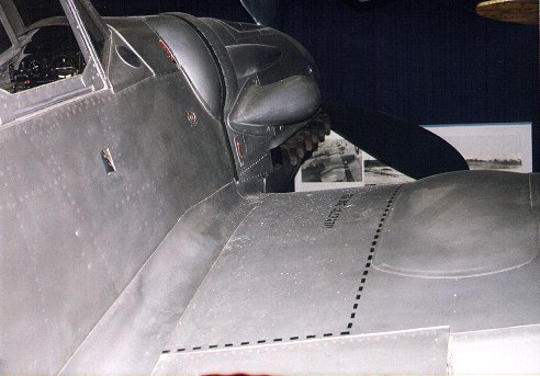
The following photographs concentrate, therefore, on close-ups of the aircraft's unique features, mainly the bulges in the nose of the aircraft necessitated by the introduction of the Jumo 211 and the two-seat cockpit.
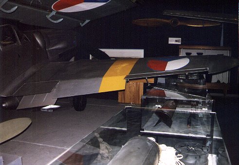
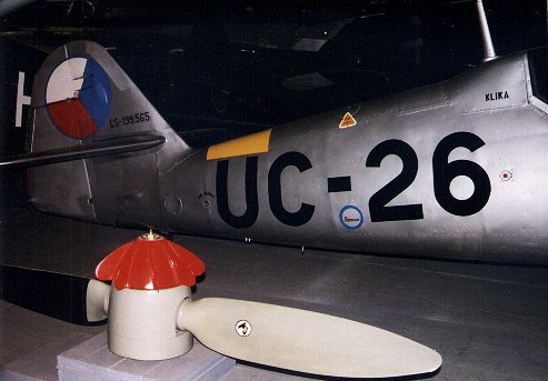
The aircraft is painted in overall silver with national markings on the tail and upper and lower wing surfaces and yellow bands on the upper wings and upper rear fuselage, probably to denote it as a trainer. There is rather extensive stenciling and all air inlets seem to be highlighted in blue. There is a red star with a wreath and socialist slogan painted on the port nose.
The Nose
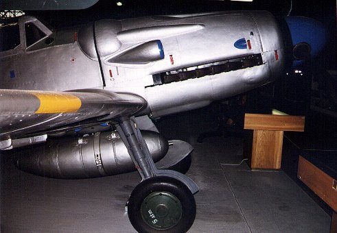
Starboard photo showing the large bulges covering the cowl-mounted 13mm machine guns (eliminated in the trainer version, with the cowl muzzle openings faired over) and the engine bearers for the Jumo 211 engine. The forward rake of the undercarriage is well demonstrated.
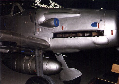
Another starboard view. Note the wide stance of the undercarriage, so unlike the early model Bf109's.
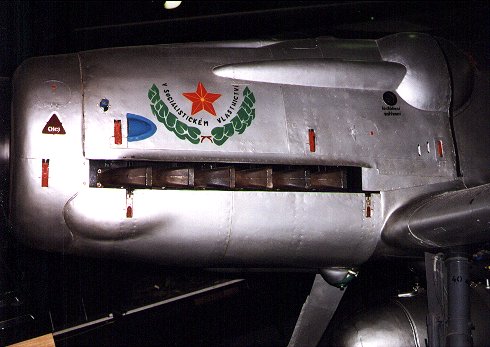
A port view of the nose.
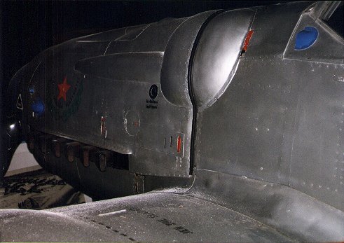
Close up view of the nose showing the fairing over the exhaust and the wing to fuselage joint.
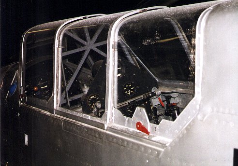
The Cockpit
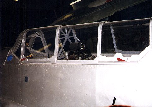
The two-seat cockpit of the CS-199 trainer had sliding canopy sections, unlike the Bf109 trainer which had a hinged canopy opening to the starboard.
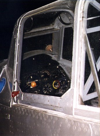
The trainee's seat up front featured the full cockpit instrumentation.
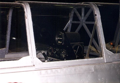
The instructor's station in the rear included only the basic instruments such as the highly visible turn-and-bank indicator at the top of the triangular dashboard.
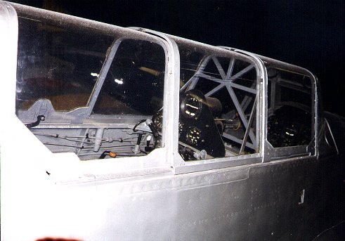
Additional views into the cockpit.
The Wings
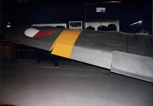
Rear view of the port wing showing the placement of the national insignia and the very prominent yellow wing bands denoting a training aircraft. The overwing wheel well bulge is seen to be relatively subtle and featuring a small step at the wing surface.
A view of the starboard wing shows the lowered flaps and offset aileron.
Flap, aileron and oil cooler flap all displaced.
An impressive array of bumps and bulges characterize the CS-199.
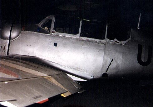
The Fuselage and Tail
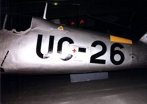
This port view of the fuselage shows how the extended cockpit was faired in. It also shows the placement of the call sign and yellow fuselage band which denoted a trainer craft. A first-aid kit was located inside the central panel and the fueling port was located just behind the radio antenna mast on the aircraft's spine.
A similar view of the starboard side.
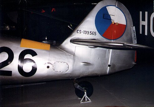
The CS-199 featured the larger tail of late model Bf 109's.
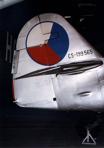
Notice both the adjustable and fixed trim tabs on the rudder with a tail light at the bottom. The taped seams of the fabric-covered rudder are barely discernible, and there is absolutely no fabric texture to be seen at all.
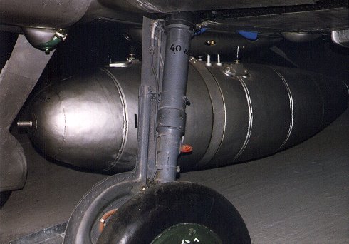
The Undercarriage
Views of the CS-199 undercarriage show the centerline droptank to advantage. Note that the plumbing is missing; there should be a pipe running from the cap (with wing-nuts) on the droptank into the front hole in the mounting point. These photos should provide enough information for most modeler's desire for detail. Notice the asymmetric bulge in the lower engine cowling and the prominent bulge in the center protecting a filter for the Jumo 211 engine.
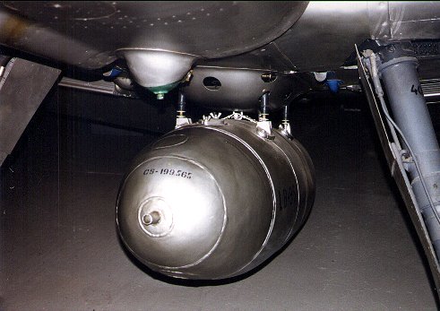
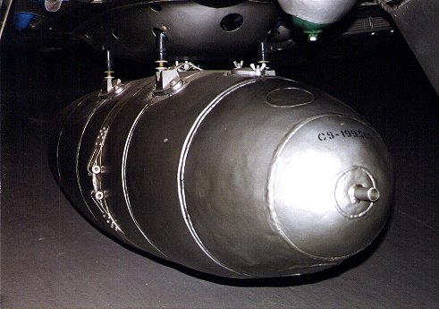
The metal strap around the center of the tank provided the primary support, with the four pylons acting as anti-sway braces.
Back to HyperScale Main Page
Back to Reference Index