Home
| What's New |
Features |
Gallery |
Reviews |
Reference |
Forum |
Search
Home
| What's New |
Features |
Gallery |
Reviews |
Reference |
Forum |
Search
|
|
|
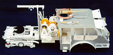
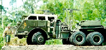
"Dragon Wagon" Pacific's M25, 40 Ton Transport Vehicle 120mm Scratch-Built Project By Robert Waltman
Step
1 (per the kit instructions):
·
Next, the engine cover was measured out, drawn
on sheet plastic (.020) and cut out. Detail
was added with GL-127 nuts and bolts, strip and rod styrene, and Techstar
tread-plate. ·
The shifters and knobs are from the truck kit
modified for proper appearance. ·
The air horns are from a 1/25th-scale
truck kit detailed and cut to size.
Step
2 (per the kit instructions): ·
First was the transfer case.
This was taken from a 1/25th-scale truck kit and modified from
photos. ·
The additional side frame detail was built
with sheet and strip styrene (.020) with final details being added with GL-127/8
nuts and bolts. ·
The taillights were fashioned from disc cut
out using a Waldron Punch and Die (WP&D) set, set into styrene tube fit to
size and detailed with strip styrene. Step
3 (per the kit instructions): ·
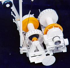
The first item in this step was the winch
drum. The interior is made from the
appropriate size tube styrene with the outer disc being made with an Olfa circle
cutter and .020 sheet styrene. Each
of these two outside disc was detailed with strip and the centerpiece made with
the WP&D set. ·
The towing cable (which is added later) is
small gauge picture frame wire. I
used this because it has the flexibility to wrap around the winch drum but still
maintains is rigidness without “kinking” up. ·
Now the front springs and winch “well” are
completely scratchbuilt from strip and sheet styrene. Final detail again with GL-127 nuts and bolts. Step
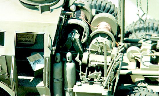
4 (per the kit instructions): ·
The basis for the power steering unit was
fashioned from sheet styrene (.020). The
steering column and reservoir were made from tube styrene and detailed with
strip. The smaller details are
GL-127 nuts and bolts and rod styrene. ·
The air cleaner box is again sheet styrene
with the 2 air cleaner’s cut-to-size brass tube. Hose connection points are smaller gauge brass tubes with
clamps made from strip and GL-127/28 nuts and bolts.
·
The winch drive unit is 3 various size drive
shafts from the spare parts box with the take-off unit being fashioned from
sheet and rod styrene. ·
The final part is the steering linkage, which
was made from styrene rod and sheet plastic.
The pivot points are detailed with disc cut out and these are detailed
with GL-127 nuts and bolts. Step
5 (per the kit instructions): ·
The front axles, drive shaft and uprights are
highly modified parts from the 1/16th scale truck kit.
As with previous items, the reference photos and TM’s were used to
extensively detail them with strip, rod and GL-127/28 nuts and bolts.
The axle did had to have Ľ inch on each end cut off to match the M26s’
proper size. Final assembly was
completed with the uprights being positioned so the front wheels could be
turned. Step
6 (per the kit instructions):
·
The rear axle was taken from the 1/16th
scale truck and was cut to size. Some
minor details were added with the GL 127 nuts and bolts along with strip
styrene. Step
7 (per the kit instructions): ·
Basically after the construction of the tandem
axle unit I completed the first part of this step by attaching the two halves
with the axle in the center. ·
To complete step 7, I scratchbuilt the
remaining items from sheet and strip styrene, detailed with GL 127 nuts and
bolts. These items were attached
with Weld-On 3. Step
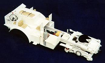
8 (per the kit instructions): ·
At this point the front axle unit and the
completed tandem axle unit were attached, making sure to carefully align the two
drive shafts before gluing with 5-minute epoxy. ·
The final part was the attachment of the
tie-rod, which I gave a slight turn to the left. Step
9 (per the kit instructions):
·
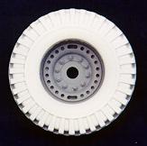
Andrew Meyers also made the rims or wheels.
These are from Ultra Pro Shape turned on a lathe.
He then drilled out all of the “guide” holes for the placement of the
studs and lug nuts, which I added with brass screws and nuts.
The casting was completed as per the tires. Step
10 (per the kit instructions): ·
Here the completed rims and tires are to be
attached. At this point I completed
(painting) all of the tires and rims, constructed them, and set aside.
I did not attach any of these items until the truck itself was completed
(painting). At that point I
attached them with 5-minute epoxy to brass shafts I fashioned earlier. Step
11 (per the kit instructions):
·
The two jerry cans are from the Verlinden
line. The straps to hold them in
place are made from strips of metal foil cut to size and super-glued in place.
The brackets they fit in are strip styrene. ·
The air hose that attaches from the air
cleaners to the motor is a re-worked piece from the 1/16th scale
truck kit. I detailed it with GL
wingnuts and GL 127 nuts and bolts. ·
The firewall is made from .020 sheet styrene
and Ľ inch strip then glued in place. ·
The instrument panel was first cut from .020
sheet styrene. All of the gauge
openings were cut out with a WP&D set.
The dials are cut-to-size from K&S aluminum tubing.
All of the switches are cut from brass rod and super-glued in place.
The buttons are cut out with the WP&D set.
The instruments themselves are decals from the spare decal box with epoxy
dropped in place to give the appearance of lenses. ·
Next item was the shift column.
This is just a re-worked column from the 1/16th truck kit. ·
The final items are the Commanders table and
the first aid kit. Both were made
from .020 sheet and 1/8 inch styrene. The
markings on the first aid kit are dry transfers from Verlinden. Step
12 (per the kit instructions): ·
At this point I did not add any of the figures
it shows in the instruction sheet. I
did attach the steering wheel major converted from the 1/16th truck
kit. I also scratch-built the
parking brake and glued in place. Step
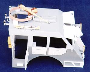
13 (per the kit instructions):
·
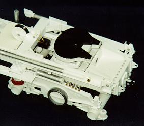
The start of the cab assembly began by placing
all of the dimensions on the drawings I had made.
Then I cut out the 9 sections. Next
I cut out all of the windows and doors along with the “cupola” opening.
These items were set aside to be detailed later.
Once this was completed I took all 9 sections and carefully glued them
together. Assuring that all of the
angles were correct. Interior
bracing was fashioned from 1/8 inch strip styrene and detailed with GL 127 nuts
and bolts. Exterior details (i.e.
hinges, signal lights, and bracing) are all made from 1/8 and Ľ inch strip and
rod styrene and brass. Final items
are the front windows, which were cut to size from .010 clear Squadron sheet.
These were set aside to be attached later after painting and weathering.
·
The 2 side decontaminating apparatus’ are
scratch-built from styrene tube and strip.
Decals are from the spare decal box. ·
The 4 canteens are from the Verlinden line. ·
The actuators for the front engine doors are
made from styrene rod and again detailed with GL 127 nuts and bolts! Step
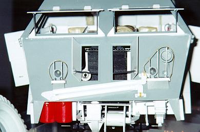
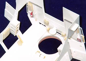
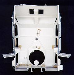
14 (per the kit instructions): ·
This step involved more detail and additions
to the interior of the cab plus the attachment of the rear panel.
The rear panel was made from .020 sheet styrene with additional interior
details being added with strip and rod styrene. ·
The jerry can is from the Verlinden line and
attached with aluminum foil. The
bracket is made from strip. ·
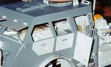
The .50 cal ammunition racks were
scratch-built with .020 sheet styrene and 1/8 inch strip.
The ammo boxes are cut-to-size resin cans I modified from the Verlinden
line. The straps for each row of
cans were fashioned from sheet aluminum strips. ·
The side seat backs were constructed from
2-part A&B epoxy putty. This
was textured with a T-shirt to give it the canvas look. ·
The two side fire extinguishers were taken
from a 1/20th scale Tamiya kit and modified with strip and rod to
make them correct. A bracket was
made for each one out of .020 sheet styrene and again the strap was made from
1/8 inch strips of sheet aluminum. ·
The two canteens are from the Verlinden line. ·
The three grenade cases are modified Verlinden
ammo boxes originally for 1/35th scale vehicles.
Dry transfer lettering is also from the Verlinden line. ·
The first aid kit was taken from the spare
parts box and modified with strip styrene.
Dry Transfer logos and lettering is from the Verlinden line also. ·
The flare case is also from the spare parts
box and was completed as the above piece. ·
The M2 machine gun barrel is from the
Verlinden line with a bracket to attach it to the rear panel made from strip and
detailed with GL 127 nuts and bolts. ·
The final item is the front bumper.
This was fashioned from .060 sheet styrene and detailed with strip and GL
127 nuts and bolts. This was set aside for placement later. Step
15 (per the kit instructions): ·
The photo-etched items were all measured to
size and cut from Techstar tread-plate and set aside until they were needed for
upcoming steps. Step
16 (per the kit instructions):
·
Next was the M2 gun tri-pod.
I took the remaining items from the Verlinden kit and scratchbuilt the
remaining pieces to complete the required details.
Once this was attached I made the straps from sheet aluminum, cut to size
to fit the brackets. ·
Next items were the front hook attachments,
which were fashioned from sheet styrene and drilled out. ·
The side steps are made from plastic
tread-plate, cut to size and then attached in place. ·
The tool compartments (2) for the shovel, pick
axe, and hatchet was made from strip styrene and then attached in place. ·
The steering unit cover is .020 sheet styrene
laminated for the curve then set-aside for final construction and attachment of
the cab. ·
The two toolboxes on the aft of the cab are
from the Verlinden line and attach with super-glue. ·
The final items are the two whiffle tree
attachments. The base is a piece of
strip and the “hook” is a section of tube styrene cut in half and attached
to the strip. Step
17 (per the kit instructions): ·
The first item built in this step is the two
headlights and their brackets and brush guards. I made the lights from a 1/48th scale MK 82 bomb
that I cut the first ˝ inch off. This
was used to fashion the light frame itself.
Next I added the attachment points which were made from strip.
The lenses are from the good ‘ol spare parts box and touch up with
epoxy. The platforms and brackets,
which hold them, were made from .020 sheet styrene, which was cut to size and
detailed, with strip and GL 127 nuts and bolts. ·
The blackout driving light was a spotlight
taken from a 1/25th scale truck kit and detailed with 1/8 inch strip,
then attached to the bracket next to the left headlight. ·
The brush guards were made with 1/8 inch strip
brass bent to shape. The individual
braces were also made with 1/8 inch brass strip and 5-minute epoxied to the
guard frames. Once completed they
were attached to the light brackets. ·
The siren was made in the same fashion as the
headlights with the exception that the forward section is an inverted siren
light from a 1/25th scale police car. These were then detail with strip and placed on the bracket.
The lens is a sequin cut to size. ·
The final item in this step is the drawbar.
This was made from Evergreen I-beam cut-to-size.
Attachment points are fashioned from sheet and strip.
Once all of the items were completed they were then attached to the front
of the cab. Step
18 (per the kit instructions): ·
At this point I made the tools for the cab.
The left and right tool compartments were made from 1/8th and
Ľ inch strip. The tools are all
scratchbuilt from strip and rod styrene and Ultra Pro Shape that was carved to
size and shape. These items were
then attached to the cab in their appropriate places. ·
The M32 gun mount was fashioned on a lathe by
Andrew Meyers out of Ultra Pro Shape. The
three attachment points were made from 5MM strip cut-to-size and detailed with
GL 127 nuts and bolts. The
remaining item was the attachment bracket for the .50 cal. This was made with, again, sheet and strip cut-to-size and
detailed. Step
19 (per the kit instructions):
·
The exhaust was made from aluminum tubing bent
to shape with a K&S tube bender. The
muffler is larger tube aluminum detailed with strip.
The muffler guard is made from sheet styrene and attached to the muffler.
The exhaust guard was made from perorated brass sheet from PSM
engineering, which was bent to the appropriate shape with a sheet metal bender.
This was attached with 5-minute epoxy to the exhaust brackets.
·
The whiffle is scratchbuilt also with sheet
styrene cut to size. The lower
attachment point is made form styrene tube.
The pip pins are made from brass rod. ·
Andrew Meyers using Ultra Pro Shape and
turning them on a lathe made the acetylene and oxygen tanks which I then molded
and cast. I added the platform from
sheet and the brackets are made from brass strip and rod. ·
The final item was the toolbox.
The basic tool box is made with .020 sheet styrene.
The splash guard was also made from sheet styrene.
The top of the tool box (platform) was made with Techstar treadplate. All items were detailed with the GL 127 nuts and bolts. Step
20 (per the kit instructions): ·
This step involved attaching all of the
previous items made in step 19 with the exception of the pintle hook and tow
hooks, which were scratchbuilt.
Step
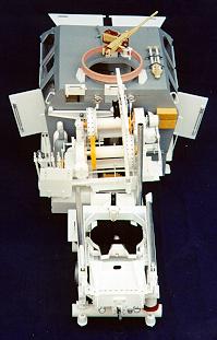
24 (per the kit instructions): ·
The rear, clutch, brake, and gearshift levers
for the front and rear winches along with the engine clutch pedal were all built
from strip styrene. The handles for
each are made from rod that was formed to size. As before with everything else, the final details were made
with GL nuts and bolts. ·
The final attachment of each lever took
careful alignment. To assure myself
of proper attachment I studied the diagrams in the TMs to make sure all were in
place and attached to their respective actuators (made from styrene rod).
I worked from the inside out in the placement.
Once this was accomplished, the engine clutch pedal was attached to its
respective rod. Step
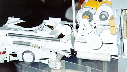
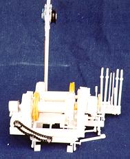
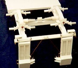
25 (per the kit instructions): ·
This step involves the scratch building of the
“A” frame. I made this from
K&S telescoping aluminum tubing. Smaller
tube had the holes for the pins drilled out before insertion into larger piece.
The front and rear attachment points are made from strip styrene. ·
I did not attach the winch assembly at this
time. It was set aside to be
painted and weathered and then attached during final assembly. Step
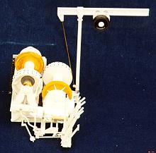
26 (per the kit instructions): ·
The two spot lights are from a 1/25th
scale truck kit. The mounting
brackets and hinges are scratch-built from aluminum tubing and strip/rod
styrene. These were then detailed
with GL nuts and bolts of various sizes. ·
The chain hoist is made with sheet styrene and
discs cut out with the Olfa circle cutter.
End caps are made with the WP&D set. ·
The crane started with a 114MM section of
Evergreen “I” beam. The rod on
which it sits is a 110MM length of styrene rod with an aluminum base.
Pivot point details are made from GL 127 nuts and bolts.
The column rod is cut-to-length brass rod. Step
27 (per the kit instructions): ·
This step involves attaching the two
spotlights and crane. The tire
tongs and there attachment pieces were fashioned from sheet styrene.
These are photo-etched items in the kit so I took their dimensions and
drew these out on sheet, which I cut out. I
set these aside for later. The
chain was added last. Step
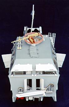
28 (per the kit instructions):
·
The M2 machine would not be attached until the
final assembly stage. It is the
Verlinden item, which was assembled, painted, weathered and set aside for that. ·
The tarp is sculpted from 2-part A&B epoxy
putty. The straps are cut strips of
sheet aluminum. The brackets are
made from strip. ·
The roof spotlight is scratch-built from rod
and strip. The handle is from the
spare parts box. ·
The two rear view mirrors are made from rod
and strip with the “mirror” part being made with a paper hole punch.
A piece of reflective sequin cut out with a paper hole punch was added in
the final assembly. ·
The spare wheel and front chain were also
added during the final assembly.
Step
29 (per the kit instructions):
Step
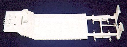
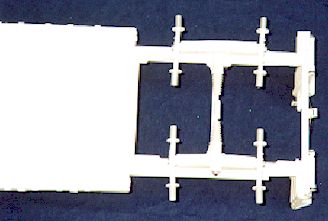
30 (per the kit instructions): ·
This step involved adding the top portion of
the trailer and the attachment points for the loading ramps.
Using the previous drawings I scaled out the dimensions on .060 sheet
styrene cut the various pieces out and then attached were appropriate. ·
The attachment points for the ramps were
handed fashioned from .020 strip styrene and drilled with 2MM holes for future
attachment of the ramps themselves. Step
31 (per the kit instructions): ·
This step involves attaching the side steps to
the trailer. These were made from
.040 scale thickness sheet styrene with a treadplate design.
Once each of the 15 sides was cut out, they were attached in a stair-step
fashion. ·
The next items are the 4 side frames which are
the tool box doors. Theses were
individually scratch-built with .030 sheet styrene. The door latches were individually made for each door, as
were the hinges, which were made with strip and rod styrene. ·
The final item of the step was the scratch
building of the trailer lights. I
used strip for the base. The
individual light frames were cut out of .020 sheet styrene with a hole punch.
These were cut in half to simulate each frame part.
The light themselves are WP&D disc #6 cut from .040 sheet, then cut
in half and attached between the frames. Final
details are GL 127 nuts and bolts. Painting
was accomplished after final assembly and painting/weathering of the trailer. Step
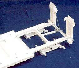
32 (per the kit instructions): ·
The support legs for the trailer where all
made from .020 sheet and strip styrene and h and u shape from Evergreen.
The pads are re-worked from a 1/16th scale truck kit.
As with everything else the remaining details are GL nuts and bolts. Step
33 (per the kit instructions):
·
Note: the trailer wheel and rim were
previously made during the truck wheel assembly. Step
34 (per the kit instructions): ·
At this point I attached the two previously
made axles to the existing trailer framework.
I aligned these and centered them for later attachment of the wheels. ·
The trailer lights were cast with CR-300 after
the originals were scratch-built with strip rod and styrene. Step
35 (per the kit instructions):
·
The loading skids were constructed with .020
sheet and various sizes of strip. As
with previous items these had to be scaled out with the calipers and then drawn
to the appropriate scale were I then transferred all of the measurements on to
the sheet. The handles for the
skids are made from 1mm brass rod bent to the appropriate shape. Step
36 (per the kit instructions): ·
The cable guide assembly (basic framework) was
made with 3mm and 5mm strip. The
“rollers” were made from acrylic rod cut to size with the end caps being cut
out with an Olfa circle cutter. ·
The jacks started out with a scratch-built
item, which was molded and then cast with CR-300. ·
Tie-downs are made with 2mm brass rod. ·
The trailer cable hook-ups started with the
first one being scratch-built. I
then made a mold and cast the other three (two for the truck). Step
37 (per the kit instructions): ·
All of the following items were constructed at
this point with .020 sheet styrene, painted, weathered and set aside: the wheel
guard assembly (4), removable skids (4), wheel block (4), plate (2), jack (2),
and platform skid (2). Step
38 (per the kit instructions): ·
Once the trailer was completed (painted and
weathered), all of the items from Step 37 were attached. ·
The pulley was scratch-built with disc being
cut out with the Olfa, detailed with 2mm/.020 strip and detailed with GL #127
nuts and bolts. Step
39 (per the kit instructions): ·
This step was basically where I attached the
completed (finally!!!) model to the base. The
black tubing (for trailer/truck electrical hook-ups) was attached at this point
also.
All of the base painting was done
with olive drab. This was then
followed up with a light dusting of faded olive drab.
The details were painted with the Vallejo acrylics.
For
decals I took the 1/35th scale decal sheet and scanned it with
DeskScan. I took this and increased
the initial scan by 219%. I then
printed this with a Color Laser Jet 4500 on Detail Master decal film.
Once the end item was completed I sprayed the final product with Testors
dull cote to preclude any of the copied material from scraping off.
Here’s were you have to be care because you now have one 81/2 X 11 inch
decal, so you have to cut out each item separately.
These were applied with a modest application of Solva-Set to “lay”
the decals in place.
The
groundwork is celluclay colored with brown acrylic before applying to the board.
While still wet I applied a generous amount of Hudson & Allen forest
litter, maple leaves and grass. Once
everything had dried I drybrushed various shades of earth tones to “blend”
the figure, model and remaining items together. The
sign is a Verlinden item attached to a Ľ inch square piece of bass wood,
stained with Weather-all.
Tools / Items Used 1.
The following items are from VLS: Grandt Line Nuts and Bolts
Hudson & Allen Studio
On The Mark Models
Tamiya
TechStar
Model Master (II) Paints
Verlinden Productions
Warriors Scale Models Inc.
Yanks Miniatures
Waldron Model Products
2.
The following items are from: Precision Scale
Model Engineering (33 Harding Street, Milford, MA 01757-2215 ((508) 478- 3148))
3.
The following are from: Plastruct (1020 South
Wallace Place, City of Industry, CA 91748 ((626) 912-7016))
4.
Following items are from Micro-Mark:
5.
Evergreen Sheet and Strip Styrene (various
sizes) 6.
Acryl-Blue Glazing Compound (putty/filler) 7.
Plasti-Cote T235 Grey Primer 8.
A&B 2-Part Epoxy Putty 9.
K&S Tubing (aluminum and brass/various
sizes)
1.
War Department Technical Manuals
(Reprints sold by: Portrayal Press, P.O.
Box 1190, Andover, NJ 07821) -
TM 9-767 (40 Ton Tank Transporter/Truck-Trailer
M25) -
TM 9-1767B (Power Train for Tractor Truck M26,
Component of 40-Ton Tank Transporter Trailer, Truck M25) -
TM 9-1767C (Body/Chassis/Winches for Tractor
Truck M26, Component of 40-Ton Tank Transporter Trailer Truck M25) 2.
MVJ Military Vehicle Journal #8 (Various
photos of the M26 and M26A1) 3.
Military Modelling/November 1996 (Article on
Tank Workshops M26 with various photos/how-to’s) 4.
Steel Masters (date unknown) (Article on
diorama by Giles Peiffer on DES’ M26. Great photos) 5.
M26 article by Robert Mellichamp (Lots of
various 1/35th plans and drawings.
Some are rough though.) 6.
Various color detail (very detailed) photos
provided by Bob Collington (72 total) from the following web-site:
-
http://www.buffnet.net/~tonym/models.htm
(gallery 6/7/8) Article, Model and Images Copyright © 1999 by Robert Waltman
|

 ·
· ·
· ·
·
 ·
· ·
· ·
·
 ·
·
 Overall weathering was done I
applied several coats of Testors Dull-cote before the wash.
Overall weathering was done I
applied several coats of Testors Dull-cote before the wash.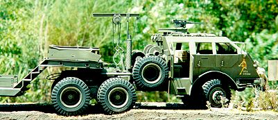 Base
was made from a piece of 1x12x48 inch poplar wood.
Base
was made from a piece of 1x12x48 inch poplar wood.