Home
| What's New |
Features |
Gallery |
Reviews |
Reference |
Forum |
Search
Home
| What's New |
Features |
Gallery |
Reviews |
Reference |
Forum |
Search
|
|
|
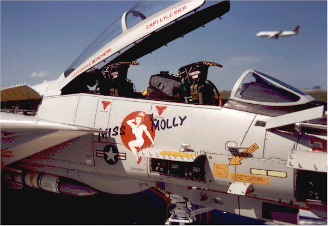
Grumman F-14A Tomcat by Cam Tetrault images by Vern Gwin
My original idea was to achieve was to create an attractive and super-detailed F-14A Tomcat without spending a fortune on after market items. I therefore chose the Revell 1/32 scale F-14A kit. Bert Kinzey writing in "Detail and Scale" points out that, although the kit has been around for close to 20 years, it still builds into a good representation of the plane. However, the kit does have a few problems. More on those later.
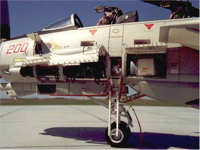
The first decision was "what to open up"? The "F-14 Walk Around" book from Squadron Publications was very useful. I wanted the radar, side panels for the gatling gun and radio compartments open. Things would not be right if the boarding ladder and foot rests were not open. The first complication crops up here. I also wanted the cockpit open and detailed which normally would not be a problem unless you cut holes in the cockpit sides Revell never intended. The recessed foot rests interfere with the cockpit tub. After lots of dry fitting and measuring I was able to incorporate the foot rests into the the left hand cockpit console. All the recessed compartments followed this pattern --- keep dry fitting, measure more than once and make templates out of card stock to keep the two front fuselage sides fitting together.
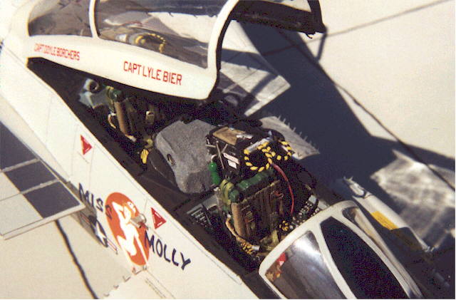
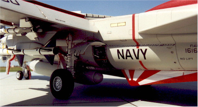
It was necessary to shave and sand down the nose wheel well. This part had to go in early so that the compartments could be measured against it for fit. Before the nose wheel well was glued in it was detailed with wiring and piping. All the landing gears were detailed by having the molded tension springs and hold downs replaced and brake lines added. The nosewheel well and nosegear have 81 extra parts. The cockpit tub, seats and instrument panels had to be glued in early in the process to keep the fitting problems in check. I used the kit seats as a starting point since they are accurate and with detailing look good. I added real cloth to the seat cushions, guitar strings for corrugated hoses and other metal tubes and wires for ejection handles. Photoetched seatbelt buckles were used with hemming silk from the sewing shop for the seatbelts. I drilled out the instrument faces and left the kit bezels in place. Clear plastic and decals simulate a realistic look of instruments under glass. The radar and computer screens were cut out and Gunze clear green paint was used to tint clear plastic which was backed by tinfoil. The foil gives the screen a glow when light hits it. As a morale booster I tacked a picture of the RIO's girlfriend to the rear cockpit dash. Map cases with maps were added to the cockpit sides ( even with GPS modern aircraft are crammed with paper maps ). The rear cockpit instrument housing was covered with fabric. I used Model Technologies mirrors and canopy latches to finish the canopy. Laser copied Remove Before Flight tags and a tag pouch complete the extras in the front offices. The cockpit area received 257 extra parts in addition to the kit parts. Once the equipment bays were built and test fitted for clearances it was time to put the details in. The GE M-61 gattling gun is scratchbuilt from 30 parts including 6 separate gun barrels. The piping and wiring in the gun bay of the real aircraft has rubber grommets to absorb vibrations when the gun is fired. To simulate the grommets I used the smallest sized heat shrink tubing available. The folding boarding ladder is scratchbuilt from 17 pieces of plastic and metal.
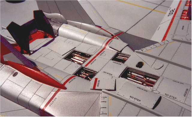
Before gluing the cockpit halves together I made the nose bulkhead so that the radar scanner could be built later. I jammed lead shot into every nook and cranny in the forward fuselage as a precaution against committing hari-kari later on. The ammunition drum compartment and the right side dorsal spine compartment are located at the glue joint with the main fuselage halves. By opening these compartments I reduced the amount of "glue-able" surface area to a point where it was necessary to make plastic tongues which would support the front fuselage when it was glued to the main body. This glue joint does not line up even when you build the kit straight from the box so get out the putty and sandpaper. Before joining the nose to the main fuselage most of the other detailed sub-assemblies must be done first. The open fuselage bays received 497 extra detail parts. The engine, fuselage top, speed brake upper and lower halves and chaff-flare dispenser openings were opened up. All of the compartments on the aircraft which were cut open had to have the surrounding plastic sanded down to a realistic thickness because the kit plastic is very thick. Detailing the opened panels is easier while the fuselage is still in halves. The bottom of the top half of the speed brake compartment was built on the reverse side of the bottom speed brake roof!!!! Confused yet! I had to plan ahead several steps at a time and build the kit in my head first before breaking out the glue.
The wings had to be finished before the upper and lower fuselage halves were glued together. I cut out the leading edge slats and flaps and sanded the plastic to a scale thickness. I also mounted brass wires in the flaps and slats and slotted where they went on the wings so they could be added after the wings were attached. I cut out the spoiler panels to match a picture I have of them deployed in an asymmetrical pattern. The wings, leading edge slats , spoilers and flaps had 106 extra parts added to them. The wingtip ID lights were cut out and replaced with colored swizzlestick plastic sanded to the correct shape.( By this time researching swizzlesticks is definitely called for !) Panel lines were rescribed at different times on the model because sometimes it was easier to scribe them after joining parts. Rivets were usually added after painting and decalling. The engine bays used 83 extra detail parts. The major problem with the kit is the wings retraction mechanism. It does not fit properly. I wanted the wings in the extended position so I braced them internally with square brass rods.
The biggest problem was the fit around the wing pivots, the plastic in this area is way to thick and must be sanded down on the inside. When the plastic is thinned down it splits when the upper and lower fuselage halves are joined and I needed alot of CA glue and sanding to make the joints fit.
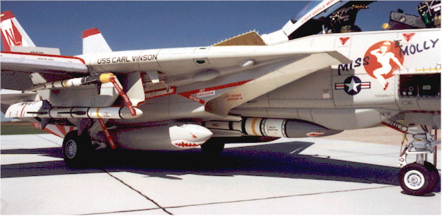
I painted the model with Model Master Gloss Gull Grey FS 16440 and dullcoated it after decalling.
The markings are VF-111 Miss Molly nose art from Super Scale both the 1/32 and 1/72 scale sets. The 1/72 shark mouths were used on the fuel tanks and one Phoenix missile.
The project took about 11 months to complete. I didn't keep track of hours but did count up the extra scratchbuilt parts which numbered 1441 in addition to the kit parts. It was a fun project and challenging to say the least.
Click the thumbnail to view the
image full size.
Model and Text Copyright © 2000 by Cam
Tetrault
|