Home
| What's New |
Features |
Gallery |
Reviews |
Reference |
Forum |
Search
Home
| What's New |
Features |
Gallery |
Reviews |
Reference |
Forum |
Search
|
|
|
Focke-Wulf Fw 190D-11 by Brett T. Green
I chose to model a 1/48 scale FW190D-11 using the "Engines and Things"
conversion, the Cooper Details cockpit, True Details bulged mainwheels,
"KommanDeur" decals and finished in Aeromaster's new Acrylic range of paints. I approached this project with some trepidation. Previous Dragon kits I have built include their FW190A-8, Ta152H, Ju88G and Me262A, which all shared universal characteristics - accuracy, good detail, value for money and rotten fit.
|
G e n e r a l C o n s t r u c t i o n |
My earlier fears about poor fit were confirmed upon examination of the fuselage.
When the fuselage parts were dry fitted at the rudder, each half bowed outward like an open banana peel. The soft grey plastic had warped considerably in storage or in transit. Also, the lack of positive location pins, plus pins being located in the wrong positions, was clearly going to complicate fuselage assembly.
Before joining the fuselage halves I prepared the inner fuselage for the Cooper cockpit tub. All interior detail and locating points were removed with the exception of the small "L" shaped locator on each fuselage half. This corresponds pretty well with forward position of the Cooper tub, and will ensure that the tub is sitting square.
The interior of the Dora's upper sidewalls were fairly spartan. I first thinned the top of the canopy opening and built a new canopy rail on each side of the canopy opening using styrene strip. Strip styrene was also used to represent structural features and the prominent canopy jettison handle. The resin canopy crank provided in the Cooper Detail set was now added.
The fuselage was now ready for assembly. Starting at the rudder and moving forward, the fuselage halves were joined with Testors cement and temporarily taped with Tamiya masking tape.
 At
this stage I chose to add the resin upper forward fuselage deck from the "Engines and
Things" conversion. The fit was almost perfect, and the whole fuselage felt much more
solid with the deck superglued in place. The assembled fuselage was set aside for 24 hours
before the masking tape was removed.
At
this stage I chose to add the resin upper forward fuselage deck from the "Engines and
Things" conversion. The fit was almost perfect, and the whole fuselage felt much more
solid with the deck superglued in place. The assembled fuselage was set aside for 24 hours
before the masking tape was removed.
In the meantime, the wings and wheel bays were assembled according to instructions.
Take care to align the upper and lower leading and trailing edges. If your example is like mine, and there is an overhang on one of the wing edges, make sure that you glue the wing with the overhang on the leading edge. It will be much easier to fill and sand the leading edge than reshape the sharp trailing edge.
I dry-fitted the wings and fuselage after the sub-assemblies had thoroughy set. The correct dihedral of the wing is guaranteed by the lower surface of the one piece wheel well. However, when the wings are mated with the fuselage I had a 1mm to 2mm gap for the length of both wing roots. Because I didn't want to change the dihedral angle I had two choices:
a) Fill the gap with Milliput or similar (Aaargh!) or
b) Install spreader bars in the fuselage.
I chose the latter.
In this instance I needed two spreader bars - one at the front and one at the rear of the fuselage wing root. I am not particularly scientific with spreader bars. I usually cut a section of sprue slightly longer than I think will be needed. I then test fit the spreader bar, dry fit the wing, trim or move the spreader bar and continue the process until the gap disappears. Superglue can then be flowed around the joins between the fuselage and the spreader bars.
Before you commence the process make sure that the fuselage assembly is thoroughly dry as the spreader bars will place a great deal of stress on the fuselage join.
The position of my rear spreader bar fouled the correct positioning of the cockpit tub. I took a wedge of resin off the bottom rear of the tub with a razor saw, taking care not to cut right through the completed cockpit. This was enough to allow the tub to be positioned inside the fuselage assembly. The front of the tub sits on the "L" shaped lugs, while the seat rails in the rear of the cockpit should line up with the rear deck.
At the same time as jiggling the cockpit tub, I superglued the photoetched cover for the rear deck. Don't forget to fold all the little locators. They will help determine the correct position of the photoetched part (and they look good too!).
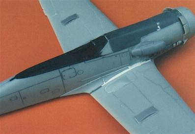
With the spreader bars in place, the gap between fuselage and wing disappeared, but a slight step was created at the forward wing root (The upper surface of the wing was higher than the fuselage wing root). I fixed this with a sausage of Milliput laid in the problem area and smoothed with a small, wet trowel. A wet finger would probably do the job just as well. A little sanding after 24 hours is all that is needed to finish a perfect join.
The only other filling required was at the lower wing fillet. The rear spreader bar had pushed out the fuselage half at this point, so once again Milliput was used to fill and reshape the lower rear wing fillet.
T h e S u b j e c t A i r c r a f t |
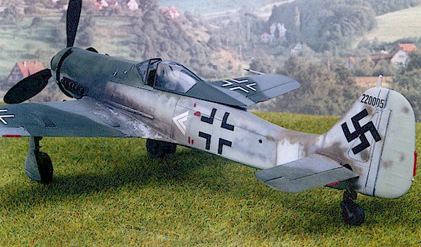
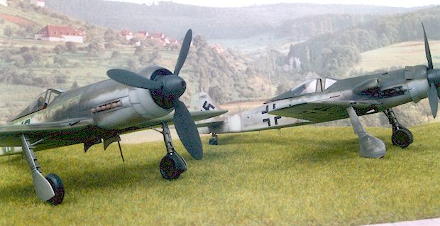
FOCKE WULF 190D-11
DOUBLE CHEVRON OF STAFF FLIGHT, JV44
WERK NUMMER 220005
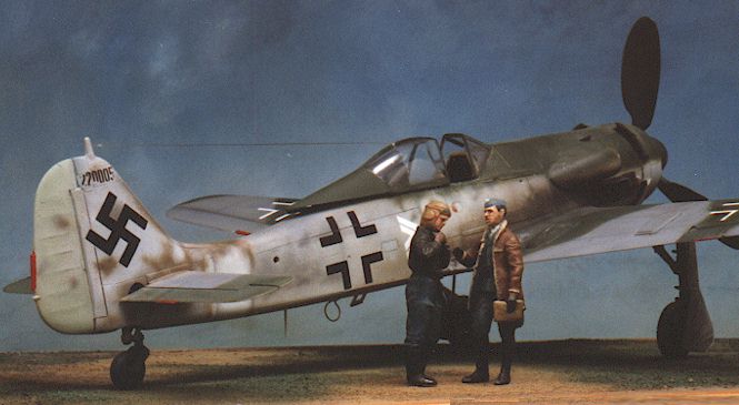
The excellent new book "JV44 THE GALLAND CIRCUS" by Robert Forsyth, contains a photograph of the subject in deteriorating condition at Bad Worishoven, August 1945.
The light paint on the fuselage extension and the extent of use of the brown-violet paint patches on the upper rear fuselage are clearly indicated. There is no evidence of stencilling on this aircraft.
Even though the exhaust staining on the mid fuselage side does not appear to be present in this photograph, it is clearly present on the side of the engine cowling. Either the sooty stain has been wiped clean by sightseeing allied servicemen, or the reflection is hiding the stain. However, I believe that, when the aircraft was in service, this typical heavy staining would have been present along the length of the fuselage as represented on my model.
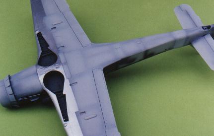
Also the reflection off the undercarriage covers indicates to me that in addition to the forward lower wing, these covers were also left in a natural metal finish.
P a i n t i n g a n d D e c a l s |
Painting
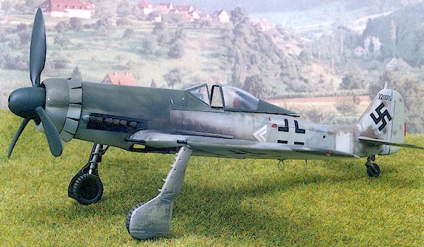
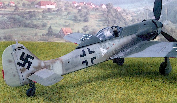
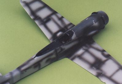
With the fuselage and wings assembled, it was time to test out those new Aeromaster Warbirds Acrylics. The colours are terrific - almost any colour that a Luftwaffe modeller would need is available. This particular machine was finished in 75/82/76 with a smattering of brown-violet on the rear fuselage.
This aircraft also featured various shades of late war Luftwaffe "sky" shades. The rear fuselage extension is a very pale shade. The leading edge of the underside of the wing is in natural metal.
 I commenced by spraying panel lines Tamiya flat
black. This was to simplify weathering later on. My technique involves "filling
in" the spaces between panel lines with the appropriate colour, then overspraying the
surface to achieve a subtle weathering effect.
I commenced by spraying panel lines Tamiya flat
black. This was to simplify weathering later on. My technique involves "filling
in" the spaces between panel lines with the appropriate colour, then overspraying the
surface to achieve a subtle weathering effect.
Unfortunately, I found that the new Aeromaster acrylics did not spray easily. The only thinner that works with Aeromaster paints is distilled water. Not even plain water. Definitely not alcohol based thinners, methylated spirit, lacquer thinners or Tamiya Acrylic Thinners. If anything but distilled water is used, the paint will congeal and string, clog up your airbrush and make a mess of your model. At least that is what happened to me!
 Even when
distilled water is used, I found the results less than satisfactory for fine lines and
mottles. The overspray was far less controllable than either Tamiya or Gunze paints.
Even when
distilled water is used, I found the results less than satisfactory for fine lines and
mottles. The overspray was far less controllable than either Tamiya or Gunze paints.
In future, I will use these paints only for large areas of solid coverage, such as undersides or the base colour of a two-tone camouflage scheme. I may also use them on the rare occasion when I am masking a pattern.
In this example, I did use the Aeromaster paints, but tidied up later with my own mixes of Tamiya and Gunze paints.
Weathering was a combination of a heavily sprayed exhaust staining and paint "chipping" courtesy of Tamiya Chrome Silver Enamel sparingly hand painted with a fine brush.
Decals
By contrast, the KommanDeur decals were superb. Register is perfect and they go on like a dream. The research and colour information is well supported, even if it is contestable in a couple of examples. I had a little silvering on the upper wing crosses, but this was my fault as I spent too much time jiggling the buggers around to get them aligned properly. I fixed the problem easily by masking around the white part of the decal with Post-It Notes, and spraying the insides of the crosses in the camouflage colours.
F i n i s h i n g T o u c h e s |
Following painting, I prepared the dangly bits for final assembly. I replaced the plastic
machine gun barrels and pitot tube with brass tube, and added fusewire brakelines to the
undercarriage legs.
Fixing the undercarriage components was another Dragon "bad-fitting" nightmare. The main undercarriage legs fit very loosely in their mounts. This makes it very tricky to accurately position the toe-in angle for the main undercarriage legs. To make matters worse, I could not get the retraction struts to fit sensibly. I made do with something that looks okay, but will not pass close inspection.
Finally, I prepared the canopy for its antenna wire. I drilled out the locating hole in the top of the canopy, the secured a length of monofilament to the inside of the canopy. I mounted the headrest and slid the canopy onto its rail. I paced the canopy in the open position and measured the correct length of the cable. I then opened the canopy further, superglued the loose end to the rudder mast and returned the canopy to the normal open position - thus tensioning the antenna.
C o n c l u s i o n |
The kit itself presented far more complications than the conversion. The paint proved to
be a disappointment but I will continue to look for a thinner that will allow me to take
advantage of the wonderful colour range; however the KommanDeur Decals were an unqualified
success. Only eleven more FW190D subjects left on the sheet!
(Ref: "JV44 THE GALLAND CIRCUS" by Robert Forsyth, Classic Publications, West Essex, England, 1996. p.203)
Back to HyperScale Main Page
Back to Features Page