Home
| What's New |
Features |
Gallery |
Reviews |
Reference |
Forum |
Search
Home
| What's New |
Features |
Gallery |
Reviews |
Reference |
Forum |
Search
|
|
|
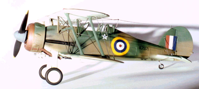
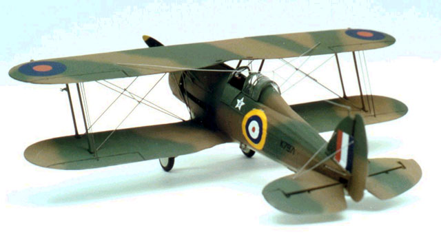
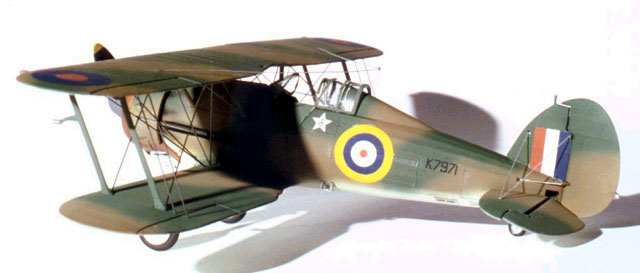
Gloster Gladiator Mk. I by Pablo Calcaterra
Some years ago I bumped into someone who was
reading a book about a British pilot I had never heard of before. It turned out
that this pilot was the unofficial top scorer of the Western Allies in World War
II - Marmaduke Thomas St. John
Pattle. Born in South Africa in 1914, Pattle entered
the South African Air Force some years before the outbreak of WWII. In 1936 he
was transferred to the Royal Air Force and by 1938 he was in Egypt with 80 Sqn,
as a Flying Officer. In June 1940 Italy declared war to the allies
and the Western Air Force squads soon became entagled with the Reggia Aeronáutica.
On August 4th, Flight commander Pattle shot down his two first enemy
planes, but was shot down himself in the same combat. A fine pilot with excellent sight and tactical management of the combats, he devised a system to shoot down the italian Savoias SM 79 that were faster than the Gladiators. His score mounted steadily. In December 1940 80 Sqn. was transferred to Greece.
With Pat's score at 15 confirmed and several
more probables, 80 Sqn. traded his battle worn Gladiators for Hurricanes I. With
the aid of this superior aircraft, his claims increased at an even faster rate.
In April, Germany invaded the Balcans, to rescue the Italians from a desperate
position and protect the "Southern front" before the invasion of the
USSR. The Luftwaffe pilots were better qualified and
equipped foes. This didn't deterred Pat, who was transferred as Squadron Leader
to 33 Sqn, with a DFC and bar. Mentally and physically very tired due to 9
months of continuos fight in ever worsening conditions, Pattle was shot down and
killed by Me110s of 5/ZG26 over Athens on April 20th, 1940 while
leading the last 12 Hurricanes (from 3 squadrons) available in Greece against a
hundred of German planes. 33 Sqn. official records were lost during the
retreat, but based on his fitters diary and testimony of his fellow pilots his
score was 51 at the time of his death (depending on the sources and authors,
this figure varies from 41 to 65 - officially, he accounted for 23 enemy
planes). A couple of years after first seeing the book by ECR Baker, I was able to get hold of a copy in the UK. The search for a Gladiator in 1/48 scale to build one of Pat's Gladiator began in earnest. This year I found the elusive (at least in Argentina) Lindberg kit in a toyshop far away from downtown, and started to gather more details about Pat’s aircraft. The Internet and e-mail were invaluable tools, and I managed to get some very important information (see credits).
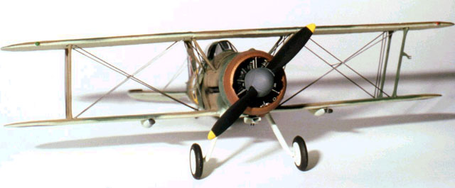
Lindberg's 1/48 scake kit is a Gladiator
II, with a top wing antenna mast and a three bladed propeller. Several
modifications must be made to turn it into Pattle's plane. To improve the kit, I purchased the following
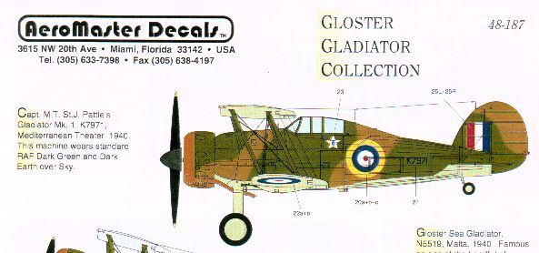
aftermarket products: two bladed propeller by Aeroclub P419, Airwaves
photoetched interior AC 48087 (I didn't use the flaps supplied with this set)
and Aeromaster decals 48-187. Lindberg kit has some flash and ejector pins marks are quite evident, specially in the undersides of wings and tail planes. These need to be filled and sanded, thus spoiling in some degree the plastic and the excellent fabric effect achieved.
Both doors were cut out from the fuselage
sides, as the photoetched ones are much better and can be placed
opened or closed. The etched ones were marked over the fuselage, and then
the cutting took place. As usual, I started with the cockpit. From the
original kit, the only usable part is the stick. The rest (seat, floor and
instrument panel) are quite simple and much better replaced by the photoetched
parts. Also included in the Airwaves set are the seat harnesses, knobs, compass
and the structure of the sidewalls. The seat, floor and some of the levers must
be backed with plasticard (1 mm). The
seat lever was made from stretched
sprue that came from a price tag! All the interior was painted interior green
and drybrushed silver. The photoetched horizontal compass
needs the adition of a base made of the body of a missile that came from
the spare parts box and a longer and thinner missile made the support of the
compass, which was superglued to the floor.
The black instruments panel, compass, stick, and floor were drybrushed
silver to highlight the details. The instruments and compass where given a drop
of clear barnish to resemble the glass. The stick was glued placed to the left
and forward, as I planned to give some movement to the tail of the Glad. Very visible from the cockpit are the two
Brownings 303. I scratch build them with plastic card, painted them black and
drybrushed them (although there are aftermarket products to avoid this job).
They were placed inside each fuselage half.
Next, the structure behind the seat was glued
with cyano. The straps were placed from this part, through a whole in the
headrest, until they fall on the seat. With everything dry and in place, the
fuselage halves are carefully glued. Fit is not very good, specially in the
undersides, which must be very carefully filled and sanded with wet and dry
paper, to avoid erasing the panels (nevertheless, some rescribing had to be
made). Both doors need to be bended gently against
the discarded plastic ones, to match the correct curvature. The handles were
assembled and adhered to the doors.
Everything was painted interior green, with some weathering with silver and
black knobs.The elevators were cut from the tailplanes and hinges were made from
plasticard and left aside. The rudder received the same treatment and left aside
till later. The tailplanes and fin where glued carefully, and the photoetched
supports for the last one were fitted with cyano. The 4 photoetched fuselage
handles (two for each side, close to the tail) were glued in place. The little engines consists of only 2 pieces
(front and back), which I painted black and drybrushed aluminium. The radiator was glued to its place, on the
top right side of the nose. The
lower wings were assembled to the fuselage. Care must be taken so they keep the
right angle though the fit is tight and this is achieved easily. Next, the three-part top wing is glued. Before
the glue dries, the struts are fitted to the lower wings. Then the top wing is
placed on top of the struts and aligned properly. I left it overnight this way,
to avoid the pieces from moving. When dry, the top wing was taken aside. Filling
and sanding is needed to cover the joints of the three parts. As Pat's Glad was
a Mark I, the radio antenna had no mast. This implies that the hole for the mast
must be covered with putty and sanded (again spoiling the fabric effect). The
fuselage struts need some putty and sanding to melt them with the surface. Before adding the underwing machine guns the
rectangular ejection hole for the empty cartidges was opened in each of them
using a cutter blade. The legs were fitted with the internal hubs.
The rectangular pin of the legs needed a lot of sanding and filling to receive
the hubs. I preferred to used the foot step supplied by
Lindberg, instead of the photoetched which was not round (like the stick). A demanding task was the research for the tropical air filter fitted to the Gladiators. Thanks to pictures of desert Glads supplied generously by Rick Kent and Alex Crawford and the ones I had of Blenheims (that used the same Mercury engine), I was able to scratch build the filter. The main body is made of a couple of plasticard pieces glued together and shaped to resemble the non rectangular filter (it's found in one of the pictures of a 80 Sqn. Glad and I think it gives this piece a little more appeal than the more commonly found rectangular one). Then the air intake was made from the plastic tray of modified atmosphere packed pasta bended to shape, and the cover attachments were made from tiny pieces of copper wire.
Now the elevators were fitted slightly
dropped, and the rudder was glued to the fin, swinged to the left. The propeller was sanded heavily to take away
all the surface imperfections and flash. A nail cut to the proper length was
glued with cyano to the hole in the back of the two bladed propeller.
With everything dry, and the cockpit covered
with pieces of wet tissue, painting could begin. Matt black was airbrushed along the panel
lines and moveable parts. The interior of the cowling and all 4 machine guns
were painted this colour as well.
The area around the engine was also painted black, for it to look darkened when
the camouflage paints were applied. Wheels and propeller blades were given a
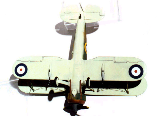
black coat as well. Prior to painting the undersides (RAF sky -
Humbrol HB5), the ejector holes were covered with Maskol. Long thin strips of
masking tape were used to protect the four machine guns and the guide for the
ones on the side of the fuselage. A very gentle and smooth application of RAF
sky was given to the undersides, trying to let some of the black
"stain" the camouflage. This gives the plane a battered look. The sand
filter and wheel hubs were painted unattached. The air intake was painted
silver. The propeller blades were masked with tape,
exposing only the hub (painted dark grey as per the doubtful Aeromaster
instructions) and the tips (painted yellow). As it had taken so much work to build the
interior, I decided to use the opened hood parts. Regretfully, the sliding part
is molded as one with the rear part. All the parts were covered with masking
tape, and then the frames were carefully exposed cuting out the masking tape
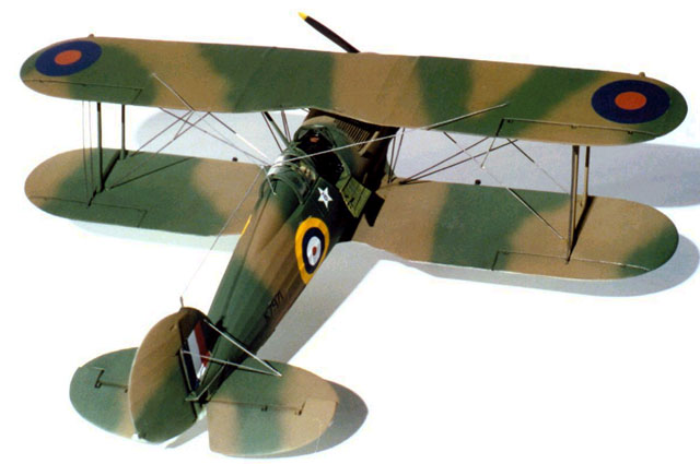
using a scalpel. The interior of the cowling was masked with tape. Research for the topside colors was difficult, as the different sources differ about the layout of the fuselage. Based on the picture in Pat's biography, I agreed with the scheme supplied by Aeromaster up till the tail. I consider that the design they give for the tail is wrong, taking into account Rick Kent's drawings at Internet and the cover of the book, plus the scheme given to all the other fighters in RAF use. So here I have deviated from the instructions given by the decals producer.
Something else that the Aeromaster
instructions lack of is the lower wing paint scheme. Here I used the drawing of
the cover of the book as a reference, plus a part of a picture of a Glad that
can be found inside the book that confirms the "chart" of the cover.
Paints chosen were Humbrol 29 and 30. Again, in the black pre painted places, airbrushing was thinner to let some of the base color show through.
With the paint dry, I very gently and smoothly
airbrushed the heat black lines of the 9 cylinders to the front of the fuselage
of the plane. To paint them in the correct place, I dry fitted the engine, and
marked with a pencil the place of the cylinders. I also retouched the stains of
the machine guns. The cowling was masked with tape, to expose only the front
part, which was given a coat of copper. When this was dry, it was drybrushed
with Humbrol 133 to represent the weathering effect of the heat. The exhausts
were painted with this same color, using a a brush. The ailerons and flaps lines were marked with
a very thin black pencil, as were the grids of the radiator.
All the surfaces were given a coat of gloss varnish. The Aeromaster set depicts K7971 in which, on August 8th, 1940, Pattle shot down his victims #3 and 4, two Fiats CR42 of 9ş and 10ş Gruppo C.T.
No stencils are supplied
by Lindberg or by Aeromaster. The lower wing and fuselage roundels have
the red spot as another decal, to be centered properly by the modeller. They
adhered very well, and Set solution was only used for the fuselage roundels in
some tricky places like the zone close to the cockpit and the rectangular
inspection panel. Some silvering was still evident.
The decals were difficult to stick to the etched support structure of the tail.
The little details of the step formed by these became too much for the decals,
that couln't follow the whole of it, even with the use of Set solution. I
think that the family badge (behind the cockpit) is a little bit
oversized. When the decals were dry, matt varnish was
sprayed on all surfaces to seal them. Here's when the silvering showed mainly
around the fuselage roundel. The carrier film beside the blue strip of the tail
decals was cut away carefully with a scalpel, as it exceeded the surface of the
fin because the swinged rudder didn't leave place for it
to be sticked.
With everything ready for the final stages
(which turned out to be more time consuming than thought), the final assembly
begun. The navigation lamps were painted: red and
green (Humbrol 2 and 19) for the wings and silver for the one in the tail. The
upper wing was glued to the struts. There was no problem here, as the previous
alignment worked fine. The wheels and outer wheel hubs were attached.
No glue was needed for the "rubber" piece, as it is very well
supported by the hubs. This gives them freedom of movement and they turn freely. As no gunsight is supplied, it had to be
scratchbuilted using pieces of plastic cut to shape. An unused missile was used
to make the calibration device which goes below the main body of the gunsight.
The glass rectangle was made using the pasta tray again. The light was painted
silver, and the leather pad was given a coat of brown. There are some more pieces missing in the Lindberg kit, that must be scratchbuilt to make a good engine: the 3 struts that support the collector ring of the cowling, and the two air intakes. The first ones were made from stretched sprue and painted silver, while the second ones were made from a glass capilar I was given in a Surgery shop, painted black and weathered with silver. Again, pictures gave me the help I needed, as to where to place them. The cowling was fitted to the engine, and the glass tubes were glued with cyano. The lower part of the air intake (kit piece # 41) was cut to the proper length to receive the sand filter, and placed inside the cowling, With everything ready, the complete engine/cowling set was attached to the front fuselage. Exhaust pipes were glued in place carefully. The small supports that link them to the fuselage where made with tiny lenghts of copper wire, glued with cyano to the exhaust pipes and painted Humbrol 133.
Some little extra supports for the sand filter
were made of copper wire, painted black. The air filter was glued in place. Two
"L" bended pieces of wire make the attaching arms below the filter
(when writing the article, after taking the pictures, I discovered they should
have been placed much more separated). Aluminium drybrushing was given to all the
panel and bolts of the fuselage, wings, machine guns and engine cowling.
The rigging supplied by Lindberg consists of a
very long piece of elastic wire. To make the bracing wires, the supplied one
must be cut with a blade to the length needed for each part. The instructions
given by Lindberg are incomplete, as some rigging (specially the one close to
the fuselage) is missing in the
drawing. No length for each one is given by the manufacturer. The picture of the
box and the photos I got via Internet helped me a lot to get this straight.
Measuring the length for each place was tricky but I managed not to loose any
bit of wire. The wire was glued with cyano. Regretfully, my fears became true when I
discovered the length of the wire
supplied by Lindberg was not enough. The 4 top tailplanes and the rudder cables
were made with copper wire, handled very carefully to avoid bending it. Once in
place and glued with a tiny drop of cyano, the copper wire was painted aluminium
with a small brush. Two pieces of thicker wire were glued at the cross of the
main wing rigging (also missing in the instructions). The antenna in the Glad I was made of 2
lengths that went from the wings to a supporting
wire behind the cockpit (middle of the fuselage). From this, a single wire went
to the tail mast. I glued the short wire of the fuselage first, to use it as a
support. Then the tail to fuselage one was stucked with cyano, and finally the
wing ones joined the middle fuselage support. More cyano was given to this
critical place where 3 wires meet,
to strenghen the join. I placed a paper between the wings and the wire, to be
able to paint the copper wire easily with a brush soaked with aluminium color.
All the arrays were painted this same color.
Lindberg has produced a kit that, with some work and aftermarket products, can be turned into a very attractive representation of the Gladiator. I was sad that this project had ended, as I had enjoyed so very much the almost three months I spent building the plane of the true ace of aces, Pat Pattle.
To Rick Kent, Alex Crawford, Richard Caruana and Brian Nicklas (at the Smithsonian) for their disinterested help. To Juan Carlos Ostolaza who took the pictures.
1.
Pat Pattle, Ace of Aces - ECR Baker 2.
Gloster Gladiator home page - Alex Crawford 3.
Military History Journal Vol 1, No3 - The South African Military
History Society - Douglas Tidy 4.
Aces high volume 2 - Christopher Shores 5.
Commonwealth biplane fighter aces - Intenet (www.dalnet.se) 6.
IPMS Stockholm web site (for Rick Kent's profiles and detailed pictures
of a Finnish Glad) 7.
www.1000pictures.com
(yet another aces list) 8.
Going solo - Roald Dahl 9.
Pictorial History of the Mediterranean Air War Volume One, RAF
1940-1943 - Christopher Shores 10.
Met.open.ac.uk/group/jwl/glad.htm (detailed picture of the engine) 11.
Hurricane aces 1939-40 - Chris Holmes 12.
Bristol Blenheim - Theo Boiten 13.
Me 110 Aces of WWII - John Weal 14.
Spitfire - J.A. Guerrero
Model and Text Copyright © 2000 by Pablo
Calcaterra
|
 To
be able to place the photoechted instrument panel, a piece of plastic guide
inside the left side fuselage half must be scrapped away, like the floor guides
which are a couple of milimiters shorter that the photoetched replacement.
To
be able to place the photoechted instrument panel, a piece of plastic guide
inside the left side fuselage half must be scrapped away, like the floor guides
which are a couple of milimiters shorter that the photoetched replacement.