 Home
| What's New |
Features |
Gallery |
Reviews |
Reference |
Forum |
Search
Home
| What's New |
Features |
Gallery |
Reviews |
Reference |
Forum |
Search
|
|
|
Hanriot HD.1/HD.2 by Fred Hocker
Eduard's Hanriot HD.1/HD.2 in 1:48 scale
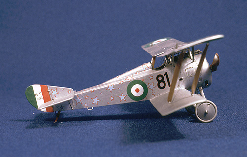
Having long been shy of attempting models of WWI aircraft, partly as a result of traumatic memories of trying to rig biplanes with 9-year-old fingers, I finally took the plunge. A Classic Airframes He51 showed me that rigging was not so bad if a little forethought and care were used, so I decided to try a few of the interesting aircraft that pioneered air-to-air combat. A little research indicated that one of the most respected names in 1:48 injection-moulded biplanes was Eduard, and their products were readily available at my local hobby shop at ridiculously low prices. The first I purchased was an Albatros D.III, always one of my favourite designs, but the first I built was the Hanriot HD.1. I actually purchased this kit on a whim. I knew nothing about the type, but the paint scheme depicted on the box made an instant sale. After a string of RLM 74/75/76 grey fighters, how could I resist a silver machine covered in red-bordered blue stars?
To be honest, I do not know much more about this type than what is described in the instructions. Hanriot designed the aircraft as a replacement for the Nieuport 11, but the French decided not to purchase it in great numbers as it was felt that it would not be a big improvement over the Nieuport. Undeterred, Hanriot marketed the machine to other Allied forces, and both the Belgians and Italians bought the nimble little fighter, and it became the type most used by the Italian air forces. Willy Coppens, the great Belgian ace, scored most of his victories in Hanriots. The Americans also investigated the type, using them for trials on battleship turret launchers after the war. Two main variants were produced, HD.1 and HD.2. The former had a conventional fixed undercarriage, while the latter was intended as a floatplane (but some machines were made with wheels). As with all WWI aircraft, there was a fair amount of variation within a single type, and individual pilots personalised their mounts, both aesthetically and mechanically, so no two aircraft were exactly alike. The basic layout is a conventional, late-war "sesquiplane," with a larger upper wing staggered forward of the straight lower wing. The fuselage is wood framed, tube reinforced and fabric covered, with alloy sheet over the forward portion and around the cockpit. The wings are fabric-covered wood, while the tail surfaces are fabric over steel tube. A Le Rhone 9-cylinder rotary, one of the more refined engines available, usually provided power for the HD.1 in either , in either 110hp or 120hp versions. Armament for the HD.1 was usually a single Vickers machine gun, synchronised to fire through the propeller arc (the HD.2 used two of these). The overall package is nicely proportioned and reminiscent of the Nieuport it was supposed to replace.
Eduard offers several versions of this kit, including two different ProfiPack versions with resin and photo-etched details and extra marking options. I purchased the wheeled ProfiPack kit. The two sprues of dark grey, soft injection-moulded plastic that form the core of the kit are up to Eduard's usual recent quality (imagine if Hasegawa did biplanes...), with good finish, thin sprue gates, excellent mould alignment, and no flash. The engineering is excellent, with the fuselage to lower wing join and upper wing/strut geometry very carefully thought out. Unlike other biplane models I could mention, it actually takes some effort to get the upper wing alignment wrong on this model. There are alignment pins or stubs on the fuselage halves, smaller parts locate positively, and the surface detail is outstanding. This is not your dad's short-run plastic!
Three resin pieces are provided: an alternate fin/rudder and wing-mounted generator for one of the HD.2 versions, and a very nice drilled-out venturi intake that mounts on top of the upper wing on some versions. There is a single clear part, the injection-moulded windscreen and surround. This works well due to the heavy construction of the Hanriot's screen. Decals are provided for four different aircraft, two HD.1 and two HD.2 (all on wheeled undercarriages), but only one saw action; the rest are post-war. The star-spangled machine of Italian pilot Antonio Bogliolo (81a Squadriglia) was in use in 1918. The other three options are an HD.1 of the Belgian 5čme Esquadrille (1921) with five-colour camouflage and shooting star on the fuselage, the modified HD.2 tested by the Americans in 1919 (sporting an all-grey scheme - dull, dull, dull), and a French HD.2 of the Escadrille de Chasse AC1 (1919) in four-colour camouflage. The decals are by Aeromaster, and are opaque and in register. There are over 80 stars in three different sizes for the Bogliolo aircraft!
A lovely bonus, especially for those of us without an extensive reference library, is a single sheet with eight colour photographs of details of the restored HD.1 at the RAF museum. Everything you need to detail the cockpit, wire attachments, etc. For only eight photos, there is plenty of information (I would have liked one of the engine). As far as accuracy goes, I had the chance to compare the kit to the real thing when visiting Hendon recently. Generally speaking, Eduard has done their homework and the errors or omissions are relatively minor. The exhaust collector as shown in the instructions is backwards, the headrest padding is missing, there is a vent hole missing from the cowling, the instrument layout differs very slightly from that on the preserved example (but there was likely some variation in the originals), etc. None of these problems are difficult to remedy, and the clues to them all appear on the photo sheet Eduard provide. The one difference that might be harder to fix is at the tail end of the fuselage, which was open on the original but is moulded as closed. Dimensions all scale to within a few centimetres, which is the practical limit in this scale and medium.
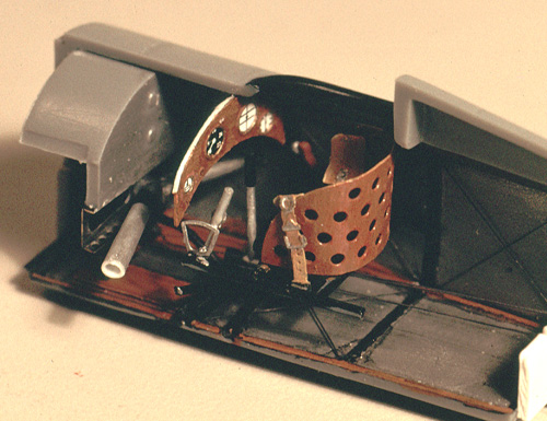
I elected to build Boglioli's machine, as will most buyers. This means a single machine gun, standard rudder, no wing-mounted generator, no cowl extension on the bottom, and no venturi on top of the upper wing. I also chose to add detail where I could, even though the kit comes with plenty to begin with. WWI aircraft are actually fairly easy to detail, as everything was made out of tube, rod, sheet, or wire to begin with, and it is strangely rewarding to add tiny bits in dark spaces that no one will ever see... The cockpit is very well thought out by the kit engineer, with copious detail. A total of 21 pieces are used to create everything from the tiny tubes supporting the control column pivot to separate foot straps on the rudder bar. I added the wire cross bracing to the cockpit floor and fuselage sides, using quilting thread (diameter 0.004 inch) run through holes drilled at the joints and held in place with cyano glue. I also added the rudder control cables to the rudder bar, but this was sufficiently exciting to discourage me from adding the aileron control cables from the bottom of the stick.
There are two options for the instrument panel and its four gauges, either a decal onto a styrene part or printed film onto the back of an etched panel. I went for a combination of the two, as the film gauge faces were black with white markings but the real instruments (and the decal) used white faces with black markings. So I glued the decal to the back of the etched panel. I also replaced the flat etched seat cushion with one carved out of thick sheet styrene to represent the rather deep upholstery on the original. A similar cushion was made for the headrest. Final additions included the fuel line (brass wire) on the port side of the cockpit and a three-dimensional lever for the throttle quadrant. The overall effect is more than busy enough, but most of the detail is invisible once the fuselage is assembled, so I took a few pictures at this stage. The only real problem with the engineering of the cockpit assembly is the use of a rather thick, separate floor piece onto which most of the rest of the parts are mounted. This effectively moves everything a little too far up into the cockpit, making it seem a little squashed (if I had added aileron cables, they would have exited above the wing, instead of inside the wing), and makes it impossible to open up the footstep in the port side. In the grand scheme of things, it is one of the compromises that kit engineers have to make, and in this case they fudge it pretty effectively. The second area where I felt compelled to lose control was with the engine. Eduard provides a beautifully moulded crankcase and cylinders (I think there are even the correct number of cooling fins on the cylinders), with an etched starfish that goes on the back to represent the exhaust collector. The large openings in the lower part of the cowl do show the tops of several cylinders, so I thought I would add some of the missing detail. First, the flat etch piece really did not look like exhaust pipes (and the instructions show it facing the wrong way, for those who decide to use it), so I decided to make up individual pipes from brass rod of appropriate diameter. Then there had to be valve gear on top of the cylinder heads. One thing led to another, and soon my wife could hear me gibbering contentedly to myself as I sat trying to cut out individual rocker arms from .005 inch styrene. In the end, I couldn't stop. So, each cylinder received an exhaust pipe (brass rod), exhaust pipe mounting block (styrene sheet), rocker (short piece of styrene rod with a tiny rocker arm on each end), pushrod (steel wire), spark plug (styrene rod) and spark plug wire (fine copper wire). Total number of added pieces: 72. Total number of added pieces that can actually be seen once mounted behind the cowl and propeller: fewer than 20. The pushrods are on the back and so are totally invisible, the spark plugs are behind the cowl, and only two and a half cylinders peak out of the cowl vents... But now I am looking forward to doing a Fokker E.III, with the bottom four cylinders completely exposed! The cowl needs an extra slot cut into it, at the bottom, just in front of the large central slot, and it really should be thinned to look a bit more like sheet metal. Other modifications include the replacement of the kit tailplane bracing struts with lengths of styrene rod (easier than scraping the mould seam off the teeny weeny kit parts) and the addition of the undercarriage bungee cords from copper wire. I also made a replacement tail skid (after I sacrificed the original to the cracks between the floorboards). The tail end of the fuselage is completely closed on the kit, but the restored aircraft in England has the last 25 centimetres or so open, so that the springing for the tail skid is visible. I elected not to change this. Like most kits, once out of the cockpit and the engine bay, the rest is pretty simple. The fuselage halves fit very well (no filler needed here), the empennage is a simple two-piece assembly, and the lower wing join requires only a little clean up to go together smoothly. The undercarriage suffers from a weak joint where the axle meets the two struts, thus the use of wire to simulate the bungees also makes this stronger. Assembly of the upper wing is greatly assisted by the design of the original aircraft. This had a rigid frame mounted on the top of the fuselage forward of the windscreen, a tent-shaped structure over the gun. The wing bolted to the ends of this frame, so a pair of positive locating points are readily available for the kit builder. Spot-glue the wing to this frame, then add the interplane struts to firm up and align, then add the simple cabane struts once the main assembly is set. I am told that the arrangement on Accurate Miniatures' F3F is even more idiot-proof, but this arrangement survived my attack, so it must be pretty reliable. Rigging was not exactly a breeze, but neither was it nerve-wracking. It was exactly what modelling is supposed to be - a rewarding period of focused concentration with a nice result at the end. I used a technique I found on the WWI modelling web site, using fine monofilament (quilting thread). All attachment points are drilled through before assembly with a no. 80 drill in a pin vise. On this kit, this is made very easy because all of the attachment hardware is moulded in - the strut brackets on the wings are particularly good. Once the wings are on and the struts have all dried, carefully ream out any holes that might have been closed up by paint or glue. After that, it is a simple matter of running one end of a piece of monofilament through a hole, touching it with a drop of cyano, then running the other end through its hole, pulling taught and touching it with a spot of cyano. I found that a short length of .010 inch guitar string was a very useful glue applicator, as it will go down into the hole next to the monofilament. The loose ends will stick out on the exterior surfaces of the wings. Nip these off right at the wing surface with a sharp scalpel, then add another tiny drop of cyano to fill any gap, and the outer surfaces of the wings are ready for painting.
I used Humbrol enamels throughout, applied with a brush. Much of the interior is called out as "aluminium," but it is not clear if this is aluminium dope or simply the unfinished surface of the aluminium sheeting. I opted for the latter, and used one of Humbrol's MetalCote series, matt aluminium. This polishes to a reasonable finish and is pretty tough. Reinforcement struts were of steel tube, painted semi-gloss black. The main framing, instrument panel, and seat were all of wood, which always presents a challenge in painting. The photo sheet that came with the kit was very useful here, as it showed that the framing was a lighter, more yellow colour, while the seat and panel were a redder shade with hardly noticeable grain. Given the types of wood traditionally used in northern Europe for coach framing and plywood, my guess is that the frame is ash (very stiff and strong) or perhaps spruce (very light but still strong), while the seat and panel were of plywood, either mahogany or stained birch. The phenolic varnishes used since the late nineteenth century for wood exposed to the elements have a strong amber to red cast. To try to replicate this effect, I used no 62 (leather) as a base coat, with 113 (rust) for shadow and 63 (sand) as a drybrushed highlight. By brushing the highlight in the direction of the grain, a subtle effect can be created. More or less of this highlight also affects the overall shade, so I used a lot on the framing to get closer to the brighter yellow ash. Once I was satisfied with the effect, I coated all the wood with clear varnish (no. 35), which has a slight yellow tint. While this seems to work on small surfaces, I am not sure that it will be convincing on a large expanse, such as the varnished plywood fuselage of an Albatros D.III.
The rudder is vertically striped, red/white/green, with the airframe number in the white stripe. Eduard provides a decal for the entire rudder, but I find these difficult to get right. Instead, I masked and painted the stripes, then cut the number out of the decal and applied it, then coated the rudder in semi-gloss varnish. The decal and the box art differ on the order of the stripes - is the red next to the fin or the green? I copied the decal, which means the box art is probably correct. Now for those stars! There are three sizes, the smallest just over a millimetre across. Kudos to Aeromaster for how clearly these are printed, perfectly in register. These need to be applied before the roundels, and the squadron number has to be applied to the side of the fuselage at the cockpit before the upper wing goes on. I elected to do the number, stars, and roundels before adding the upper wing and rigging. The decals go on with little trouble, although they are just thick enough that some persuasion is required to get the stars to lie down where they cross over the upper edge of the fuselage side onto the top. I had to resort to diluted white glue in two cases, but otherwise, decal solvent was sufficient. The stars are actually quite easy to apply, but it takes some time to get through all 70 or so. I ended up in something of a Zen state, and without realising it, three very enjoyable hours had passed.
Eduard continues to impress me with the quality of detail, moulding, and engineering in their kits. This tiny biplane (the wingspan is less than the span of the horizontal stabiliser on a PBY Catalina, and about 20% less than the wingspan of a Spitfire) was a pleasure to put together, with no frustrations. I increased the difficulty level by adding lots of pointless, invisible detail, but never got to the point where I wanted to throw it across the room. It was considerably easier to build and much better engineered (and researched) than the last biplane I did, the He51, and made a pleasant diversion from the WWII fighters that normally interest me. The finished product is a pretty aircraft that stands out on my display shelf, despite its small size.
For those interested in how the model was photographed, the camera was a Nikon FM2 with Nikkor 55mm macro-focusing lens. Film was Kodak Elite Chrome 160T (for tungsten lighting). Exposures were typically 1 second at f11 to f16. Lighting was two conventional, household reading lamps with 60W white bulbs. This is not the right light temperature for 160T film, so the resulting slides are slightly blue in cast. This was corrected after scanning in Adobe Photoshop 5.0 (the average correction on the Image/adjust/color balance menu was -15/0/-25). Text and Images Copyright © 2000 by Fred
Hocker
|
 Although
the injection-moulded parts are easily enough to produce an excellent model, the
ProfiPack version adds some useful detail in key areas. Eduard are well known
for their etched detail sets, in which every conceivable component is made out
of folded bits of sheet metal. Thankfully, they take a more restrained approach
in this offering, providing etch components that are (usually) an appropriate
use of this material. For example, a distinctive feature of the Hanriot cockpit
is the seat, which has bent plywood back with ventilation/lightening holes. This
is provided as a fold-up piece of nickel-plated brass that actually works out to
near scale thickness. On the other hand, the etched cushion for it is completely
unconvincing. The etched bits also include an exhaust collector for the engine,
horns and cables for control surfaces, an instrument panel, seat belt, various
cockpit bits and external access panels. One very thoughtful touch is that all
of the filler caps and panels along the centreline that are a pain to rescribed
after cleaning up the fuselage join are provided as separate etched pieces.
Although
the injection-moulded parts are easily enough to produce an excellent model, the
ProfiPack version adds some useful detail in key areas. Eduard are well known
for their etched detail sets, in which every conceivable component is made out
of folded bits of sheet metal. Thankfully, they take a more restrained approach
in this offering, providing etch components that are (usually) an appropriate
use of this material. For example, a distinctive feature of the Hanriot cockpit
is the seat, which has bent plywood back with ventilation/lightening holes. This
is provided as a fold-up piece of nickel-plated brass that actually works out to
near scale thickness. On the other hand, the etched cushion for it is completely
unconvincing. The etched bits also include an exhaust collector for the engine,
horns and cables for control surfaces, an instrument panel, seat belt, various
cockpit bits and external access panels. One very thoughtful touch is that all
of the filler caps and panels along the centreline that are a pain to rescribed
after cleaning up the fuselage join are provided as separate etched pieces. Instructions
are in Eduard's well-designed format and broken into two sheets. One sheet
features a brief bit of history in four languages, a graphic parts inventory,
and assembly instructions in two colours. These are well laid out, and leave few
questions for the builder (although there is some confusion over exactly where
one of the access panels on the bottom of the fuselage should be). The second
sheet, in black, grey and two shades of blue, provides painting and marking
instructions with four views of each aircraft.
Instructions
are in Eduard's well-designed format and broken into two sheets. One sheet
features a brief bit of history in four languages, a graphic parts inventory,
and assembly instructions in two colours. These are well laid out, and leave few
questions for the builder (although there is some confusion over exactly where
one of the access panels on the bottom of the fuselage should be). The second
sheet, in black, grey and two shades of blue, provides painting and marking
instructions with four views of each aircraft.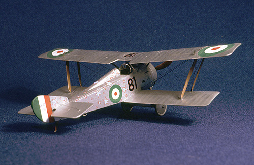 On the real
aircraft, the exhaust collector leads to a central pipe into the cockpit, where
two outlets are attached by flexible couplings (rubber cuffs with hose clamps).
These outlets run to port and starboard, where they pass through the fuselage
side and stand slightly proud of the exterior. I expect this kept the cockpit
pretty warm, as the outlet pipes run right over the pilot's shins! The kit does
a nice job of duplicating this assembly by having the central pipe and outlets
made as a single piece whose ends butt against the fuselage interior, but the
exterior ends are only slightly raised ridges. I chose to scratch-build a
replacement that would actually go through the fuselage side and have
drilled-out ends. So I cut the two outlet pipes off the central pipe and made
two new pipes from styrene tube with the outer ends drilled out to get a wall
thickness nearer scale. The drilling had to go fairly far in, as the outer ends
of the pipes are squashed into an airfoil shape where they exit the fuselage. I
did this with a pair of flat-jawed jeweller's pliers, carefully applied. Next, I
cut out the holes in the sides. Eduard's moulding includes ridges for both the
pipe end and for the raised edge around the hole in the fuselage, so it was easy
to enlarge the hole to just the right shape with a fine scalpel blade. The
tricky part is at the fuselage assembly point, as the two pipes have to line up
with the holes.
On the real
aircraft, the exhaust collector leads to a central pipe into the cockpit, where
two outlets are attached by flexible couplings (rubber cuffs with hose clamps).
These outlets run to port and starboard, where they pass through the fuselage
side and stand slightly proud of the exterior. I expect this kept the cockpit
pretty warm, as the outlet pipes run right over the pilot's shins! The kit does
a nice job of duplicating this assembly by having the central pipe and outlets
made as a single piece whose ends butt against the fuselage interior, but the
exterior ends are only slightly raised ridges. I chose to scratch-build a
replacement that would actually go through the fuselage side and have
drilled-out ends. So I cut the two outlet pipes off the central pipe and made
two new pipes from styrene tube with the outer ends drilled out to get a wall
thickness nearer scale. The drilling had to go fairly far in, as the outer ends
of the pipes are squashed into an airfoil shape where they exit the fuselage. I
did this with a pair of flat-jawed jeweller's pliers, carefully applied. Next, I
cut out the holes in the sides. Eduard's moulding includes ridges for both the
pipe end and for the raised edge around the hole in the fuselage, so it was easy
to enlarge the hole to just the right shape with a fine scalpel blade. The
tricky part is at the fuselage assembly point, as the two pipes have to line up
with the holes.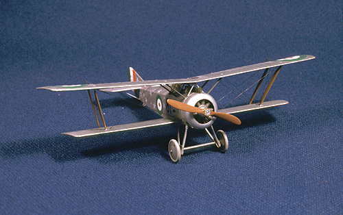 The exterior
is aluminium dope overall, with the undersides of the outboard ends of the wings
painted red (port) and green (starboard), to indicate the Italian national
colours. I used no. 191 (gloss aluminium) for the overall finish, and this has a
nice quality that looks much more like a doped finish than natural metal. It is
also not too glossy, but provides a good surface for decals. For the wing tips,
I tried painting the aluminium first on the lower and the tips first on the
upper, just to see if there was any difference in how the paint responded to
masking. No difference, the Tamiya tape does not pull up either type of paint,
but does leave a very crisp edge without a ridge. Since I used flat paint for
the wing tips, this was coated with semi-gloss varnish (135). For some reason,
this came out a little rough in texture, a problem I have not had before.
Perhaps dust in the brush?
The exterior
is aluminium dope overall, with the undersides of the outboard ends of the wings
painted red (port) and green (starboard), to indicate the Italian national
colours. I used no. 191 (gloss aluminium) for the overall finish, and this has a
nice quality that looks much more like a doped finish than natural metal. It is
also not too glossy, but provides a good surface for decals. For the wing tips,
I tried painting the aluminium first on the lower and the tips first on the
upper, just to see if there was any difference in how the paint responded to
masking. No difference, the Tamiya tape does not pull up either type of paint,
but does leave a very crisp edge without a ridge. Since I used flat paint for
the wing tips, this was coated with semi-gloss varnish (135). For some reason,
this came out a little rough in texture, a problem I have not had before.
Perhaps dust in the brush?