 Home
| What's New |
Features |
Gallery |
Reviews |
Reference |
Forum |
Search
Home
| What's New |
Features |
Gallery |
Reviews |
Reference |
Forum |
Search
|
|
|
Heinkel He 51 by Fred Hocker
Heinkel's He 51 was a conventional biplane designed by the Gunter brothers. It first flew in 1933 and by 1934 the German Air Ministry (RLM) placed orders to equip the still-secret Luftwaffe with the fighter. By the time that rearmament was made public in 1935, the He 51 was the primary fighter equipping active Luftwaffe Fighter Wings (Jagdgeschwader). The Heinkel was deployed to Spain with the Condor Legion, where the type was flown by several future aces including Eduard Neumann and Adolf Galland. The biplanes had acceptable performance for their era with a top speed of 205 mph (325 kph). However, they were soon outclassed by Spanish Republican-piloted Soviet fighters, and superseded by monoplane fighters such as the Messerschmitt Bf109.
The Heinkel He 51 represented the final development of single-seater biplane fighters in Germany. Its design incorporated evolutionary improvements over WWI aircraft but no significant advances. The rear fuselage, main planes and control surfaces were fabric covered and the landing gear was fixed with fairings. Armament was two MG 17 in the upper engine cowling firing through the propeller arc with the capacity for small bombs under the wings or on a centerline rack. A 750 horsepower BMW VI V-12, mounted upright rather than inverted (giving the nose the squared, top-heavy look characteristic of several 30's designs), drove a two-bladed metal propeller. Range could be extended with an aluminum belly tank. A seaplane version, the He51 B-2, was produced from 1936, as was a more specialized ground support (C) version.
Classic Airframes is an American company. Their kits include some components manufactured by the same company that makes Eduard products, so the contents of this box bears a similarity to an Eduard kit.
The styrene parts are typical of short-run kits from resin moulds. They are very thick and have no locator pins, but lots of mating surface to work on. Ejector pin marks are huge, but almost all are located in invisible positions. One in the rudder needs to be removed to allow the fuselage halves to join. The first impression may be disappointing if you have just finished Tamiya's latest offering, but the surface features are quite good with engraved panel lines where appropriate that are much closer to scale size than the trenches on Tamigawa products; and a subtle but clear rendering of the fabric surfaces. Surface finish is not polished, but easily cleaned up. The joins of control surfaces to planes are no deeper than panel lines, however, and need some extra scribing. Locating points are indicated for many of the bits, but some have no mechanical strength in the join. For example, there are no tabs on the inboard ends of the elevators; they glue directly to a flat surface on the side of the rudder. There is some indication that my kit was cast toward the end of the life of this particular mold as there is a little bit of blurring in places, but nothing serious. Lots of flash though - I mean you will be able to weigh the plastic you shave off these bits on your bathroom scale in pounds! The resin bits are extremely simple (the masters seem to have been nothing more than rod stock cut, bent and soldered together), but well cast. The MG 17 muzzles are nicely detailed with the ends drilled out. The photoetch fret is well executed (as one would expect from an Eduard product), with multiple layers of detail. The film with the instrument faces is clearly printed. This is the first time I have used this type of instrument panel construction, and it seems to make a great deal of sense.
Instructions consist of a single folded sheet of line art. One panel shows a profile of all the parts included in the kit, even the decals, with part numbers indicated (since these do not appear on the sprues). One side of the sheet shows the assembly of all the parts in subassembly exploded diagrams. The last panel indicates the attachment points for the wire bracing (which is extensive). Rudimentary painting information is called out in the assembly, but the key provided does not match the codes in the assembly panels. The instructions are reasonably clear, if not very detailed, but there is some dimensional information for locating some of the smaller parts on featureless expanses of styrene. A separate full-colour sheet provides painting instructions and decal placement for the exterior schemes on one side and a nice synopsis of the aircraft's history on the other Accuracy? The wingspan scales to within 2 cm, but the length comes up about 9 cm short. The shape looks right, except for the spinner, which is too large in diameter and a little too rounded. The panel arrangement seems to be more or less correct, although the sources I have disagree on what the panel arrangement was. There does not seem to be any access for the MG, unless they were removed and serviced from beneath. Tires are definitely not right. Assembly shows that the upper wing sits too low. The aftermarket does not support this a/c particularly well. I am not aware of engines or cockpit sets or wheels, for example. A separate cockpit set is not needed, due to the detail included, and wheels would be something of an effort to fit in any case. Aeromaster produce decals for several a/c, including the Legion Condor craft flown by Galland and two pre-war gray schemes for 2./JG132 and 3./JG 233. The Aeromaster scheme for a JG 132 a/c shows a different (and more interesting) pattern for the red cowl flashing than Classic Airframes' painting guide.
The instructions call for the cockpit to be assembled first. This assembly is trapped between the fuselage halves and cannot be inserted later. The components mount onto the cockpit floor/after bulkhead assembly, to the cowling (a separate piece from the fuselage halves), and to the sidewalls. Get out the tweezers, as most of the detail consists of small, exquisitely detailed bits of brass to be folded into shape. Virtually none of this will be visible through the small cockpit cowl later so you could dispense with some of it.
The painting instructions for the cockpit are not helpful. The most common colour (keyed as "E") is not identified. This must be RLM02 (another Classic Airframes kit I have lists this colour as "light grey"). There is no indication of knob or switch colours, other than black, so a little research (or imagination) is needed here. With a little work, the overall effect in the cockpit is busy, although only the seat will make an impression on a viewer without an endoscope. The finished unit is a good fit into the fuselage, where its location is positively indicated by a series of lugs. The join between the bulkhead and the fuselage halves is actually quite good, and the cockpit assembly does a pretty good job of aligning the fuselage halves. Fuselage assembly requires concentration and patience. The two halves were bowed and twisted so that the cowl and tail do not close at the same time without persuasion. A little sanding of the mating surfaces took the worst out of the hump just in front of the fin, and I chose to join the two ends in two steps. The front end goes together fairly well, although aligning both top and bottom required a little creativity with clamps.
The engine cowl is a poor fit, but is thankfully thick, so you can carve away after it is cemented in place. There is probably enough plastic here to carve a Bf109 nose if you don't like the Heinkel's squared-off appearance! The gun troughs are too shallow, but are easily deepened with a round jeweller's file. There are two small oval intakes (cylinder cooling air?) in the front face of the cowl that appear open on some period photos, when the a/c are parked, but are shown in some illustrations as closed doors. These are represented on the model by inscribed lines. I chose to open these up, even though there is no engine behind them (but it's dark in there). Because of the thickness of the plastic, the back edges of these openings need to be bevelled away. I also drilled a small, upward-angled hole on the right side of the cowling forward of and below the exhausts, as photos show. After cleaning up the moulding dross in the wing opening, and shortening the mating surface on the wing, the lower wing is a good fit (no-filler!) on the bottom surface. Along the top, filler is needed at the root, but only a little. The tail planes mate onto their flats well, so no filler is required here, and it was surprisingly easy to align the elevators. The undercarriage is a challenge to align and could benefit from more thoughtful engineering. The upper ends of the undercarriage legs mate to the bottom of the wing and the side of the fuselage forward of the wing, a very complex surface. There is a pin on the leg and a corresponding dimple (to be drilled out) on the fuselage, but the alignment is not even. If mated by the pins, one leg is farther forward than the other. Cut one pin off and rig up a prop or clamp to hold the leg in place. The wheel/spat units, in contrast, align perfectly with a decent amount of mechanical strength in the joint. The wheel/spat units are made in halves, without locating pins and without separate wheels. The tires are pretty crude, with exaggerated tread (snow tires? surplus from the tractor works?), and require substantial cleanup. I chose not to smooth and recut the tire tread, but this is not impossible. Painting instructions are not provided for the hubs, so I chose RLM02. After painting the fuselage and lower wing assembly, I began adding the exterior detail - pilot's step, pitot head, exhaust pipes. These last are 12 separate, crude pieces, one for each cylinder. I do not know why these could not be made as a single piece to fit into a recess in the cowling. Ideally, they should be resin castings so that the ends could be hollowed out as nicely as the gun muzzles included in the kit. I rigged the wire bracing for the undercarriage at this point, as it coincided with the mounting holes for two of the upper wing struts. The bracing wire was fine poly thread raided from my wife's sewing basket. Illustrations and photos suggest that the tail and undercarriage wires were of heavier gauge than the interwing wires, so my wife also supplied monofilament quilting thread ("invisible thread") for this and the radio aerial. The upper wing requires a good eye and steady hand for alignment, as it rides only on struts. Here is one place where Tamiya-level engineering would be appreciated. Biplanes are difficult to assemble in any case, but when strength and alignment depend on four spindly struts with crudely moulded, improperly angled locating pins, it can be especially challenging. In this case I blocked the assembly in place upside down so that I could get all four struts into their holes (drilled out in the wings) and then set about adjusting as the cement set. Patience and speed are required in about equal doses. After the interwing struts are dry, the cabanes can be set in place to stiffen the structure. Even then, it is easy to understand the need for all the bracing wire. If the locating dimples for the struts are used with the struts provided, the upper wing sits far too low (and of course it was too late to fix it…). If building this kit again, I will make longer struts. With the wing in place, the remaining details can be added (rear-view mirror, antennae pylons, trim tab actuators). I did not add the drop tank, as it is a ghastly, lumpy thing. The two halves do not register well, and have an elliptical section. If one is desired, it would be easier to turn it out of rod than fix the one in the kit. On to touch-up painting and decals, then rigging. AAUUUGH! Now I remember why I stopped making biplanes! Interwing wire bracing! After some trials it became clear that there is a special place in heaven for the inventor of cyano glue. I drilled tiny (no. 80) holes for the fuselage attachment points, and inserted the cut off ends in these with a little cyano and presto! Maybe I might do another biplane. It is good to plan ahead and drill the attachment holes before the upper wing is on, although the locating information in the instructions is a little vague. The windscreen material provided is not fogged by cyano, but neither is it stuck down! Back to white glue. I am still not satisfied with how this turned out, and have photographed the model appropriately.
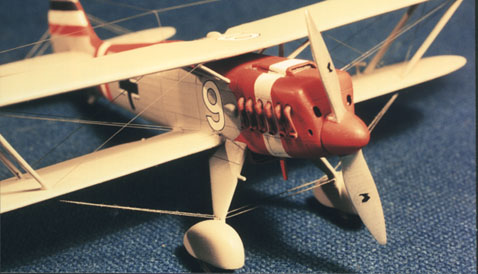
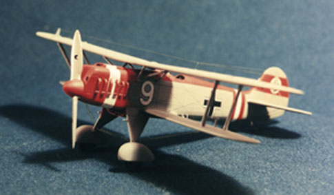
I chose "White 9" of 2./JG 132 (gray with red trim), a scheme offered by Aeromaster, for this effort, but I think I will do a second kit as Galland's mount at some point in the future. I use Humbrol enamels (because they are readily available in Denmark) and work with a brush. I suppose I should take the step up to an airbrush one day, but I like brush work! The fuselage and lower wing need to be painted before the upper wing is fitted, as you cannot get to the cockpit area otherwise. The fuselage White 9 is forward of the cockpit, and this needs to be applied before the upper wing is fitted, unless you have very tiny fingers and a rock steady hand. In my case, I completed the assembly of the fuselage, empennage, lower wing, undercarriage, intake scoop and radiator and then painted this as a unit, adding the upper wing and struts afterward. I did the whole assembly in light grey (RLM 63) and then painted on the red, white and black striping on the cowling, fuselage and fin. Aeromaster supply decals for these stripes, but I prefer to paint them on. They are easy to mask, and it is too difficult to match the colour of the painted trim to the colour of the decals. I first tried this on a P-47's D-Day Invasion stripes, and have not turned back.
As these first Luftwaffe squadrons played an important Public Relations role for the revived Reich, I expect they kept their machines in good condition. I thus kept the weathering to a minimum, adding only a little bit of wash in the gun troughs and around the radiator, exhaust and engine panels. A light highlighting of the framing under the fabric might be a possibility, but the ridging is so nicely and subtly done that I hated to spoil it with a clumsy pastel job. Panel lines were lightly emphasised with a drafting pencil sharpened to a chisel edge. I find that this makes the seam discernible without being obvious, and the fine, shallow panel lines on this kit (and other CA releases) do not lend themselves to pre-shading or washing.
Some parts of this kit are very well done (surface detail, photoetch), some require more work than your average Tamigawa kit (styrene parts fit, undercarriage cleanup), and some parts are downright embarrassing (drop tank, wing struts). On balance I found the kit worthwhile, as the overall effect is quite good and a nicely finished model is still within reach of an average modeller like me. The subject matter is also intriguing/significant and not treated by another manufacturer that I am aware of. It could do with some major engineering overhaul in certain areas, but the flaws are not fatal. This kit is not for the impatient or unadventurous, but for those interested in the subject or period it is a good addition to the shelf. As a bonus it is not a bad introduction to short-run multimedia kits.
Model, Text and Photographs Copyright © 1999 by
Fred Hocker
|
 The
Luftwaffe's first fighter was therefore relegated to ground support duties. The
He 51 was withdrawn from front-line service in 1938, but was used as a trainer
until the end of World War II. Total production was around 700.
The
Luftwaffe's first fighter was therefore relegated to ground support duties. The
He 51 was withdrawn from front-line service in 1938, but was used as a trainer
until the end of World War II. Total production was around 700.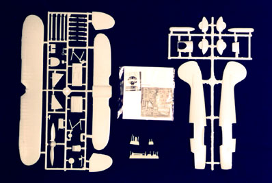 Parts are provided to
make the common fighter variant, with external fuel tank slung between the
landing gear (Classic Airframes make the floatplane variant as a separate kit).
Although a relatively simple overall, the kit does live up to the multimedia
tag. There are two injection-molded sprues (bagged together) in a light grey,
softish polystyrene, comprising the large elements (47 pieces: fuselage, main
planes, empennage, struts, cowl, propeller, undercarriage, external fuel tank,
etc.) Several blocks of resin provide a few rudimentary details (7 pieces: fuel
tank linkage, pitot head, gun muzzles and control column). A densely packed
brass photo-etch fret provides mostly cockpit detail (23 pieces), and the
instrument faces and windscreen come on a sheet of clear film. No material is
provided for the wire bracing of the wings. Some of the resin parts replace
styrene parts on the sprues, indicating that this kit was not necessarily
conceived as an integrated unit.
Parts are provided to
make the common fighter variant, with external fuel tank slung between the
landing gear (Classic Airframes make the floatplane variant as a separate kit).
Although a relatively simple overall, the kit does live up to the multimedia
tag. There are two injection-molded sprues (bagged together) in a light grey,
softish polystyrene, comprising the large elements (47 pieces: fuselage, main
planes, empennage, struts, cowl, propeller, undercarriage, external fuel tank,
etc.) Several blocks of resin provide a few rudimentary details (7 pieces: fuel
tank linkage, pitot head, gun muzzles and control column). A densely packed
brass photo-etch fret provides mostly cockpit detail (23 pieces), and the
instrument faces and windscreen come on a sheet of clear film. No material is
provided for the wire bracing of the wings. Some of the resin parts replace
styrene parts on the sprues, indicating that this kit was not necessarily
conceived as an integrated unit.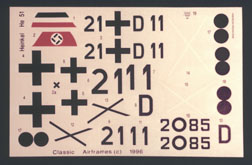 Decals are provided
for two aircraft. One is a fighter from the first squadron equipped with the
He51, I./JG 132 "Richthofen" (21+D11) in the RLM 63 grey and red paint
scheme of 1935. The other is a Legion Condor fighter from I./J88, flown by
Eduard Neumann in 1937. The decals, printed by Propagteam, are very flat with
lots of carrier film (the white crosses for the upper wings of the Legion Condor
a/c are mostly carrier film), but are in register and crisply defined.
Decals are provided
for two aircraft. One is a fighter from the first squadron equipped with the
He51, I./JG 132 "Richthofen" (21+D11) in the RLM 63 grey and red paint
scheme of 1935. The other is a Legion Condor fighter from I./J88, flown by
Eduard Neumann in 1937. The decals, printed by Propagteam, are very flat with
lots of carrier film (the white crosses for the upper wings of the Legion Condor
a/c are mostly carrier film), but are in register and crisply defined.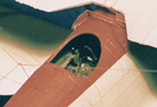 The
instrument panels are delightful and one of the quadrant/arm control assemblies
on the port sidewall is so finely etched that it has the ratchet teeth to keep
the lever in place. I would swear that the teeth even point in the right
direction. The styrene parts are plain and not terribly smooth, but make an
acceptable canvas to which to attach the fiddly bits. Some of the tube frame
detail is moulded into the sidewalls, and most of the levers attach to this.
There are no locating studs, notches, etc, to indicate where the P/E items go,
and the instructions are not terribly helpful and in some cases incorrect. If
you mount the throttle/mixture controls (I think that is what it is) exactly as
shown on the instruction sheet, it either interferes with or is covered by the
upper instrument panel (the only item with a locating shoulder), so it needs to
be moved aft about 2 mm. The upper instrument panel's curvature does not exactly
match the interior of the cowl. I attached it only at the centre, to make the
cowl less rigid for fitting to the fuselage. The seat is plain, but the detail
added by the harness is very nice and so crisply etched that it is easy to
paint.
The
instrument panels are delightful and one of the quadrant/arm control assemblies
on the port sidewall is so finely etched that it has the ratchet teeth to keep
the lever in place. I would swear that the teeth even point in the right
direction. The styrene parts are plain and not terribly smooth, but make an
acceptable canvas to which to attach the fiddly bits. Some of the tube frame
detail is moulded into the sidewalls, and most of the levers attach to this.
There are no locating studs, notches, etc, to indicate where the P/E items go,
and the instructions are not terribly helpful and in some cases incorrect. If
you mount the throttle/mixture controls (I think that is what it is) exactly as
shown on the instruction sheet, it either interferes with or is covered by the
upper instrument panel (the only item with a locating shoulder), so it needs to
be moved aft about 2 mm. The upper instrument panel's curvature does not exactly
match the interior of the cowl. I attached it only at the centre, to make the
cowl less rigid for fitting to the fuselage. The seat is plain, but the detail
added by the harness is very nice and so crisply etched that it is easy to
paint.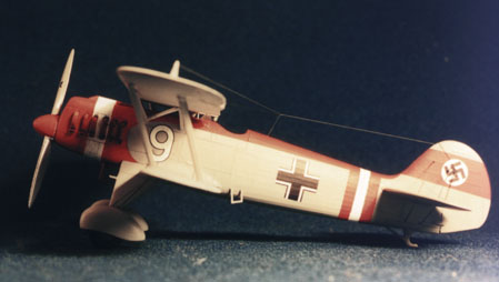 The tail is
another story. The starboard half of the fuselage is taller than the port half,
especially just aft of the cockpit, so it is impossible to avoid a step here.
The step is then awkward to remove, as the fabric-covered fuselage is faceted
and sanding removes the detail. I spent a while filling, scraping/filing and
refilling, after first marking where the ridges between facets should end up.
The tail is
another story. The starboard half of the fuselage is taller than the port half,
especially just aft of the cockpit, so it is impossible to avoid a step here.
The step is then awkward to remove, as the fabric-covered fuselage is faceted
and sanding removes the detail. I spent a while filling, scraping/filing and
refilling, after first marking where the ridges between facets should end up.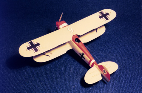 The
Aeromaster decals were not all in register, with the tail band swastikas being
noticeably off-centre. I therefore cut a white disk and swastika out of the
Propagteam decals included with the kit, and mounted this on the red band
painted across the fin and rudder. Otherwise, the relatively simple marking
scheme for this aircraft was finished with ease. Aeromaster include some
stenciling (Classic Airframes do not), such as the Werknummer and octane
triangle (not applied to this a/c). The Aeromaster decals went down beautifully,
without solvents. One of the tiny W.Nr. decals silvered slightly on the tail.
The
Aeromaster decals were not all in register, with the tail band swastikas being
noticeably off-centre. I therefore cut a white disk and swastika out of the
Propagteam decals included with the kit, and mounted this on the red band
painted across the fin and rudder. Otherwise, the relatively simple marking
scheme for this aircraft was finished with ease. Aeromaster include some
stenciling (Classic Airframes do not), such as the Werknummer and octane
triangle (not applied to this a/c). The Aeromaster decals went down beautifully,
without solvents. One of the tiny W.Nr. decals silvered slightly on the tail.