![]()
Horten
Ho 229 V6
The Pioneer Kit in 1/72
Scale
by
Glenn Irvine
|
Horten Ho 229 V6 |
| B a c k g r o u n d |
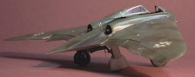
The Horten Ho 229 was an all-wing jet powered fighter aircraft that reached prototype stage by the last few months of World War II. The designs of the Horten brothers all wing aircraft and Jack Northrop's flying wings directly led to the development of today's B2 stealth bomber.
The second prototype flew but the third was captured almost complete by U.S. Forces.
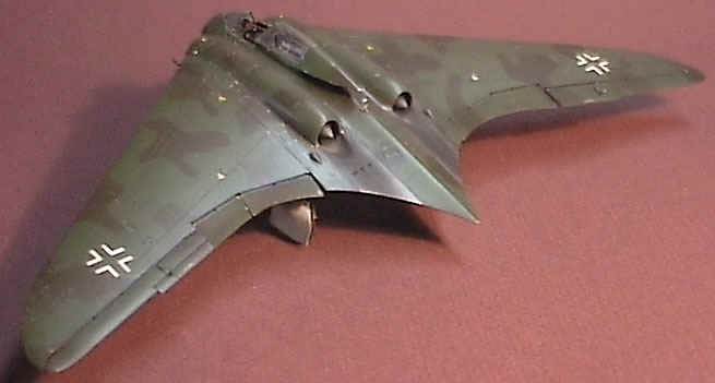
The model is depicted as the 6th prototype may have appeared when completed and used in action, had the war continued to 1946.
| T h e P i o n e e r K i t |
My first note is about a major fault with this kit - the turbine housings are too far apart. The work required to rectify this makes scratchbuilding a completely new model a viable alternative if, you were really that concerned. At the time this model was built, the Pioneer kit was new, and there was very little in the way of reference available. Luckily the Monogram "Close Up" was re-released while I was in the late stages of construction, and the Model Art book on German Jets also became available. NOW, however, I wouldnt even look at the Pioneer kit with the Revell offering available.
SUMMARY OF MODIFICATIONS
Due to the tubular framework that this aircraft used as a structure, I decided that any detailing I did would have to be done after the kit halves were assembled. This allowed me to "accurise" the external shape and build the framework to fit by cutting and test fitting repeatedly using various thicknesses of plastic rod. As there was incomplete information and references regarding this aircraft at the time certain areas were constructed using informed guesswork. The detailing was quite difficult at times because the reference photos would only show limited views and they had to be used in conjunction with line drawings of the structure and cutaway drawings and other detail drawings to deduce the function of various items visible in the structure. This then allowed me to scratchbuild the details.
 Some items that proved to
be quite a challenge included vacforming the reverse curve on the canopy. This required an
original rough master, accurate in shape, but not particularly well polished. From this a
silicone mould was made.
Some items that proved to
be quite a challenge included vacforming the reverse curve on the canopy. This required an
original rough master, accurate in shape, but not particularly well polished. From this a
silicone mould was made.
I use a flowable silicone in a tube, Dow Corning 734, which air cures over a couple of days, provided the layers are only applied 2-4 mm thick using a mould box of balsa. The balsa breathes and allows air to the silicones mould box side allowing curing, if you use plastic it wont cure this side of 2001. This silicone is cheap and convenient for small jobs. It is also transparent which allows for bubble detection both in initial moulding and when casting. Due to the slow curing and layered application you have to be patient though.
Anyway, a casting was made from clear casting resin and this was then polished till
glass smooth. A row of No 80 drill 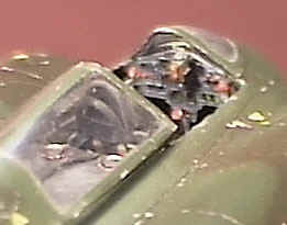 holes was made along the centre of the reverse curve to allow the thermoform
to be pulled in, the mould was mounted on my trusty vac-form rig (a plastic Tandy circuit
box 70 x100 mm, fitted with a perforated printed circuit board glued in with hot melt glue
and a rubber seal 4 mm high using neoprene rubber glued on with super glue, a hole cut in
one end to neatly fit the crevice tool on my vaccume cleaner. This works quite well for
most things, anything larger would require a bigger rig but I havent needed anything
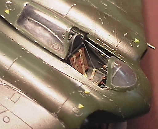
bigger , yet....). A few copies made, voila!! Internal framing was then glued in with
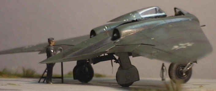
white glue. The cockpit was fully detailed with all control rods, wiring looms, levers,
etc. From my references, because of the tube frame construction there were no cockpit
sidewalls as such and the pilot could see the cannon and turbines through the framework.
This would probably have been changed in production, especially if pressurization was
required for high altitude work.
holes was made along the centre of the reverse curve to allow the thermoform
to be pulled in, the mould was mounted on my trusty vac-form rig (a plastic Tandy circuit
box 70 x100 mm, fitted with a perforated printed circuit board glued in with hot melt glue
and a rubber seal 4 mm high using neoprene rubber glued on with super glue, a hole cut in
one end to neatly fit the crevice tool on my vaccume cleaner. This works quite well for
most things, anything larger would require a bigger rig but I havent needed anything
bigger , yet....). A few copies made, voila!! Internal framing was then glued in with
white glue. The cockpit was fully detailed with all control rods, wiring looms, levers,
etc. From my references, because of the tube frame construction there were no cockpit
sidewalls as such and the pilot could see the cannon and turbines through the framework.
This would probably have been changed in production, especially if pressurization was
required for high altitude work.
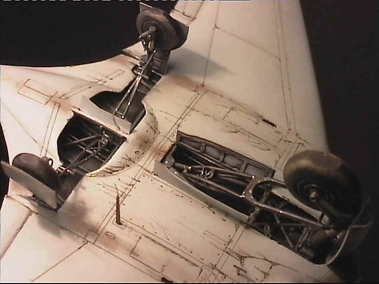
The nose wheel started life from the spares box after I found one the correct diameter. The ventilated hubs were cast up from moulds made using Italeri Dornier 217 main wheels as masters, these were then glued in recesses machined into the nose wheel. The main wheels were also spares, with machined brass hubs. The nose wheel fork was soldered out of K&S brass rod, and glued to a nose leg made from machined aluminium and plastic. The main legs were also machined from aluminium. Brake lines were added from fine lead wire and the linkages were all scratchbuilt. The nosewheel doors were all vacformed in two layers, allowing the inner layer to be shaped to produce the inner strengthening ribs,then glued together.
Producing the dropped flying surfaces provided a problem. There was so much of the trailing edge missing there was very little strength in the wing. I got around this by doing more detailing. By adding tabs of plastic card in the wing to duplicate the hinges of the flying surfaces, these allowed me to add some strength to the wing and at the same time, accurately space the trailing edge of the wing. Needless to say the wing inner surfaces were champfered to accept the leading edge of the flying surfaces which were in turn notched with a razor saw to accept the 'hinges'.
Scribing also produced a challenge. There was a rather long and convoluted panel line along the outside of each engine nacelle, which was also on a compound curve for some part of its length. I was able to duplicate this exactly side to side using a template made from thick aluminium foil taken from the top seal in a tin of Milo. This was cut with scissors after being traced to shape on the model using plans. By flipping the template over I was able to duplicate this scribed line perfectly. The soft metal allowed it to be shaped to conform to the models surface.
| P a i n t i n g a n d W e a t h e r i n g |
The paint scheme was a possible combination of late war colours - RLM 81,82,76 - being applied in a manner similar to other late war production aircraft. As there were no official RLM directives for these aircraft, the men in the field took it upon themselves to design their own schemes. The basis for the pattern came from a profile drawing in Green's 'Warplanes of the Third Reich'. Weathering was limited to a wash along panel lines with black and grey oils, and various oil stains etc. Chipped paint was shown as silver only on those panels that were metal, and as a shade of brown where the panels were wood. The exhaust blast plates were painted with Humbrol Metalizer 'steel' and lightly buffed, Gunze 'soot' was applied for the exhaust stain.
This model won its class - small scale modified - at the Model Expo in Melbourne in the early 90's.
Back to HyperScale Main Page
Back to Feature Articles Index