Home
| What's New |
Features |
Gallery |
Reviews |
Reference |
Forum |
Search
Home
| What's New |
Features |
Gallery |
Reviews |
Reference |
Forum |
Search
|
|
|
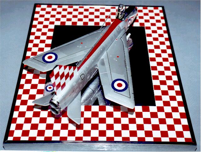
E.E. Lightning F.3 by Lee Coll
I was amongst the many scale aviation enthusiasts who were overjoyed at the announcement of Airfix's 1/48 scale Lightnings a few years ago. I purchased both versions, with the intent to build a range of machines from the F.1 on to the F.6 version. The early Lightnings appealed to me most with their utilitarian bare-metal finishes combined with the occasional flashy unit marking. While I intended to build an F.1, F.1A, or F.2, it was almost by accident that I ended up choosing the checkered-tail F.3 from 56 Squadron as my initial Lightning subject. The Lightning kits undoubtedly represent Airfix's high water mark. Precise engraved detailing, minor airframe differences, and an exhaustive decal sheet providing each and every stencil all combine to make this one of the finest 1/48 kits to date. Even with the best, there is always some room for improvement; whether it is due to the limitations of the injection molded medium or the practical considerations of maintaining a reasonable price for a kit of this size. In the case of the cockpit area, two readily available improvements can be found in either the KMC or Cutting Edge sets. I'd chosen the latter for this Lightning project, and had little problem accommodating the resin parts into the Airfix fuselage.
As construction proceeded, I noticed a problem where the intake trunking was fitted with the internal radome pylon/front wheel well assembly. An obvious gap occurred ahead of the base of the radome mount, allowing the inside of the front wheel well (and the ground beneath it) to be seen from the front of the model. A combination of some triangular chamfer inserts and the building up of the pylon base fixed this, and the intake assembly, sans radome was fitted. The weight requirement to assure the finished model rested on all three of its gear was addressed via small diameter steel shot, all epoxied around the intake trunking and cockpit area. The hollow radome pylon also allowed some weight to be added to the front end; the radome fairing itself was painted and left off until final assembly. The CE cockpit, which had been painted RLM66 and drybrushed several tones lighter was glued to the starboard side of the fuselage once all clearances had been confirmed. This proved to be a mistake; I should have let the cockpit "float" until the fuselage sides were glued together - as it turned out, a slight misalignment was evident but unnoticeable once the coaming and windscreen was attached.
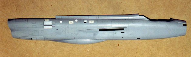
The exact panel detail on the surface of the Airfix kit is quite exceptional, but the flush NACA-type inlets towards the upper fuselage could not be molded to the same level of detail as the side inlets. I often marvel at how many hours modelers will devote to gear wells, bays, and cockpit features, only to accept incorrect or unrealistic details on the surface of their modeling subjects. I'm notoriously fussy about these things, and took the hard way to correct the inconsistent inlets. Using sliced sections of Plastruct rectangular tubing, I fashioned miniature mold boxes that accommodated the perimeter of the correct inlet detail on the side of the fuselage. These were tacked into place with white glue before brushing in a dab or two of RTV, which was allowed to cure overnight. I removed the mold boxes and the RTV molds to find perfect negative representations of Airfix's superb NACA inlets. Pushing the RTV molds a few millimeters into their respective mold boxes, I was able to create a useable inlet mold upon which I poured Vagabond resin into. A few minutes cure revealed some really nice castings of the inlet surface detail that was almost ready to replace the six (or four for the F.3) shallow inlets near the fuselage spine. Using the same rectangular stock as the mold boxes came from, I scribed around the incomplete inlet detail and eventually removed this rectangular section from the kit fuselage.
With some minor filing and trimming, the resin inlets dropped right in and were glued in place with superglue, being careful to keep the glue out of the wedge-shaped openings of the replacement inlets. This work was actually done prior to putting the fuselage halves together, so a straight-edge or similar flat surface could be used to assure the resin inlet plugs would match the profile of the surrounding surface, as the plugs were pushed out from the inside of the fuselage. A similar treatment was done on the single engine case vent on the starboard side of the aircraft, using a rectangular insert. I inserted the wrong cannon panels on the forward end of the aircraft, and could not extract the blank panels after their glue had set; my plans to do an F.2 changed instantly to an F.3!
I assembled the wings with few problems. Some of the top/bottom panel lines didn't jive where the leading edge insert met the lower wing, but some careful filling and rescribing took care of this. The area of construction that caused me the most problems was fitting the wings on the fuselage, while trying to minimize gaps to fill and assure an exact alignment. I initially built a jig that used tacked-in-place spars and two fixture stands to keep the fuselage true, with the fin/rudder exactly square to the ground. This proved too awkward, so I machined two support stands out of RenShape that fit either in the front gear well or the rear tailplane slots. I tested these fixtures by centering a rectangular piece of 0.040" styrene sheet through the wing slots in the fuselage and measuring the elevation of each end with respect to the ground, or in my case, a 12" x 18" granite surface standard. A little tweaking got it perfect and soon each wing could be glued in place with a few small spots of superglue. The wingtip elevations were checked and adjusted to assure everything was square. I noted that despite careful fitting, the forward chord of each wing at the wing/fuselage joint had an obvious gap that would be difficult to fill and sand without marring the already polished fuselage. The wings were carefully popped off, and a 1/2" x 1" piece of Bare Metal Foil was applied against each fuselage side in the affected area. The wings were tacked back in place and squared up before a liberal dose of superglue was run into the gap. Once the glue dried, the wings were popped off, pulling the adhesive backed foil off in the process. This was removed from the join surface and the superglue filler was sanded flush to the cross section of the forward wing area. Amazingly, the fit at this point was so good, that the wings now held their slight anhedral without the need for propping or support for eventual glue up.
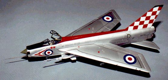
One of the most daunting modeling tasks has to be the rendering of a bare metal surface. It's also one of the most rewarding, if done right, but I had virtually no experience as an adult modeler in effecting such a finish. I'd heard great things about the SNJ system and have seen some superb metal finishes result from its use. I was able to do some trial and error with the SNJ aluminum lacquer as it makes an excellent primer when testing your seam work during construction. I was not convinced the polishing powder would be used, as it was extremely messy every time I'd experimented with it. Once the aircraft was ready for the final finish, I followed the SNJ application verbatim and was extremely pleased with the results. Three or four light, misted-on coats would eventually yield a durable, even finish that resisted masking adhesives and other handling abuse. To simulate the varying allow composition of the real aircraft's surface, selected panels were masked using BareMetal Foil. Once sprayed, and during the same evening's application the foil was removed to prevent possible blemishes resulting from the BMF adhesives. To vary the panel tones, I incorporated different metal enamels by themselves and mixed into the SNJ lacquer. The only exact mixing formulation I recall involved adding Testor's Light Aircraft Grey to the SNJ at a ration of 1:10. This mix results in a really dead flat aluminum effect.
An exception to the SNJ finishes was the use of Metalizer Burnt Steel on the tailcones. Careful application of BareMetal Foil on the nose ring and narrow tail ring at the exhaust area yielded good results; these were apparently the only two areas on the real aircraft where the metal was highly polished. The tail had been painted with several light coats of Tamiya white, then the spine was painted Xtracolour Post Office Red and allowed to dry several days before decal application began.
The kit decals are very complete, and while offering several attractive schemes, I found Aeromaster sheet 48-370 to offer the most attractive F.3 scheme, in that of XR719 with the showy red and white checkered tail. The Airfix decals have much thicker carrier films, but in retrospect, none of the kit stencils I used gave me any problems. I surprised myself after two evenings of decal application that the "touchiest" area, the checkered tail, turned out perfectly with one exception. The red decal ink was considerably darker than Xtracolour's Post Office Red. The spine looked almost orange-ish by comparison. Several test chips were made before I found that Testor's Dark Red (in the small bottles, #1104) was a near-exact match for the red printed on my Aeromaster sheet. Masking the partially decaled model proved frustrating, as I was certain I would tear up my decal work. I was able to outline the spine with BareMetal Foil only after covering adjacent decal surfaces with typing paper that was taped at it's edges, away from the decals. This worked fine, although I did pull up one of the double-layered "D" markings on the airbrakes. I stripped the damaged decal off and fretted over buying another Aeromaster sheet, just for this item! I fortunately had knocked all the little subassemblies out of the way early on, and was able to finish the model on time. The Firestreak missiles went together easily, but alignment on their pylons was nearly as tricky as the aircraft wings. Instead of following Airfix's instructions regarding the unique spine beacon arrangement that has one cutting a chunk of the spine out to accommodate a clear insert, I chose a much easier route. I punched out a small disk of BareMetal Foil and centered along the spine in its appropriate position. A drop of viscous, nearly set epoxy formed the beacon's transparency and looked really nice.
My project took about 14 months to complete; I spread the work out during this time, averaging sometimes as little as an hour each week. I am very pleased with the end result and have no qualms about starting another Lightning in the near future. I was sure the universally favorable response to this release would have propelled Airfix into a less intermittent release schedule. Visions of Canberras, Meteors, and other deserving subjects were soon dispersed, as it appears this 1/48 beauty is it for a while. Fortunately the remaining Lightning variant possibilities offer some comfort to the Anglophile.
Model, Images and Article Copyright
© 1999 by Lee Coll Back to HyperScale Main Page Back to Features Page |