Home
| What's New |
Features |
Gallery |
Reviews |
Reference |
Forum |
Search
Home
| What's New |
Features |
Gallery |
Reviews |
Reference |
Forum |
Search
|
|
|
MiG 15 bis Trumpeter's 1/32 Scale Kit In Progress by Mark A. Hernandez
Most people think that the Chinese company that manufactures this injection-molded kit is new. In fact, this company has been producing models for a long time on behalf of other name-brand manufactures. However, this is the first time they have produced kits under their own brand name of Trumpeter. Trumpeter has just released 4 new 1/32 kits. The first of these is the MiG 15 bis and the other 3 are a PLAAF F-5, F-5A and FT-5. These aircraft are Chinese versions of the MiG 17. The F-5A is a radar nose version and the FT-5 is the trainer version. I bought all four at once.
The MiG 15 appears to be a scaled up version of Tamiya's 1/48 MiG 15. It even includes the trolley to display the engine. The major difference is that all control surfaces are separate. There are four main sprues - three in light gray and one in dark gray. The dark gray sprue contains the engine parts and trolley. There are two sprues common to all four kits that contain some of the parts for the MiG 17 versions. One sprue is the dark gray one and the other has, among other things, 3 different nose rings, a different splitter plate (for the radar), two ejection seats and two pilots and two different instrument panels (these last three items are for the FT-5). You only get the two-seater tub with the FT-5 kit. The clear parts also have a different windscreen for the F-5A version. The kit includes rubber tires and a tube of glue. The decal sheet is not as extensive as Tamiya's. Chinese National insignia for the wings and fuselage are supplied, plus a set of a series of numbers from 0-9 and a couple of additional numbers (2249). There are also 4 thunderbolts, some red star kill markings and a set of black wing walks. (I hear that FROG is reboxing these kits with new decals and possibly new box art). The kit even comes with a nose weight but it is the same size as the one in the Tamiya kit. Don't count on it providing adequate ballast. The kit features engraved panel lines but not quite as crisp as one would expect. The surface finish also has a slight texture that will require sanding, especially if a natural metal finish is planned. The instructions are similar in layout to Tamiya's MiG 15.
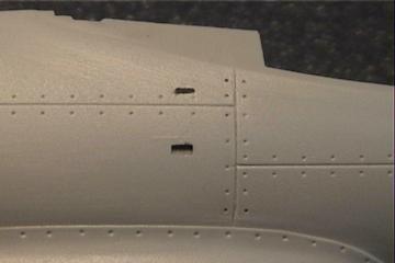
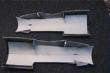
I wanted to build this kit right out of the box. For the most part I have, with a few exceptions. I started on the rear fuselage. On initial dry fitting, there seemed to be a lot of ragged flash along the interior seams. I cleaned up the excess plastic with an X-acto knife and sanding stick to ensure a good fit of the mating parts. I had to remove the locator pins on the horizontal stabilizers to get a proper fit. On the elevators the part numbers are not called out in the correct assembly sequence so be careful matching them up. The trailing edges are too thick and need a lot of sanding. I wish they could have made them as a single piece. The elevators have a flat leading edge and would have looked better if they had a rounded leading edge. There is supposed to be a trim tab on the right elevator. Trumpeter has molded it on both and did not do a good job of it. I sanded off one and partially rescribed the other one. The rear fuselage fits together well. I did notice a number of overextended panel lines and access cover lines. These were filled with CA and sanded. This was a common problem throughout the kit, along with a few stray nicks on the fuselage and wings.
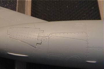
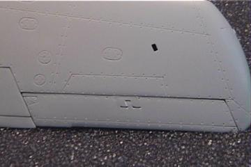
The airbrakes are not deep enough or detailed enough. I decided to glue them shut. However, that left a noticeable gap on the bottom that needed filling. There is also an extra scribed panel line on the lower rear fuselage. It's within the large rectangular panel just in front of the airbrakes. There is an extra panel inside. I can't confirm if it was really there so it will need to be filled in. (It looks like it might have been meant to be used on the MiG 17 model?) I added a small piece of plastic to the base of the tail at the exhaust outlet. Without this addition, you can look up into the tail even with the exhaust tailpipe sticking out. You'll need to do a lot of sanding to get rid of the seams on the exhaust tube unless you replace it with plastic or brass tubing.
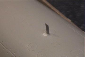
The blade antenna on the upper rear fuselage is too thick so I thinned it down. There is a depression/small cut-out in the fuselage from the seam to the antenna. After I sanded down the width of the antenna I filled this gap in with a small piece of plastic and sanded it down. I found a #78 drill bit does a good job of replacing any missing rivet detail. I worked on the wing assembly next. Before gluing the wings together you will need to decide if the plane you're building is equipped with wing tanks and which versions. The wings come with all four holes open (instead of flashed over like in the Tamiya kit). If the model is built with the small slipper tanks they will cover all the holes. If the bigger wing tanks are used then you'll need to fill in two of the holes. I repeated the trimming and sanding of the inner seams of the wing.
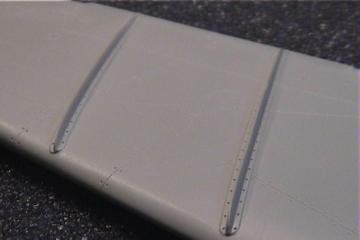
Before assembling the wings I sanded the wing fences down in thickness. In hindsight I probably should have cut them off completely and replaced them with thin strips of plastic or shim brass. The inner fence is not tall enough and both are too short in length. The Tamiya kit shares this problem They should both go to the extreme leading and trailing edges of the wing. The left inner fence needs a round section cut out. This cut out was used for the pilot to look back to see the flap extension post. The trailing edges on the wings are too thick so more thinning is called for. Trumpeter put a trim tab on both ailerons but there should only be one on the left. I had to scribe the lines for it.
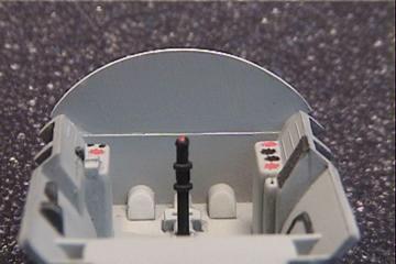
I have no idea where Trumpeter came up with the U-shaped attachments that show on the bottom of the wing/aileron joint. I can't find it in any references. Again, these control surfaces are flat butt joints. It would have been preferable to make them more realistically aerodynamic with rounded leading edges. There are sink marks on the topside right leading and trailing edge wing roots and also on the bottom left side trailing edge wing root. The fit of the right wing to the fuselage is not very good. The fuselage fillet is too high and so is the leading edge. It fits flush at the bottom though. If you build the kit with the flaps down per the kit instructions they will be in the wrong place. Like the Tamiya kit, it tells you to glue them to the back in the down position. These were Fowler-type flaps, which means they extend back as they are being extended down. You'll need to build the extension rails and also fill in the gaps at the back of the section with plastic if you plan on showing them extended. You'll also need to fill in the injection pin makes on the surfaces of the flaps. The main gear wells have nice detail but they appear to be too shallow. The cockpit and ejection seat are very sparse and could use a new resin and P/E detail set much in the same way that a few different aftermarket manufacturers have done. The instrument panel is too short and should come up to the bottom of the coaming. The main set of instruments is centred in the panel and should be offset to the left slightly. There are also no rudder pedals.
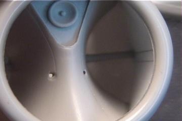
I wanted to build the forward fuselage out of the box. After dry fitting all the pieces and looking down the nose I just couldn't do it. I'm now in the process of "skinning" the interior of the forward fuselage section in order to give it a better appearance for the intake tube. Without it you can look down that large opening and seen the cockpit tub and wing attachment joints. The kit comes with the holes for the access ladder attachment open so I sealed these up. I added the top portion of the bulkhead to the front of the cockpit tub. Without it you can look into the interior of the kit. I removed the cockpit tub locating tabs on the inside of the fuselage and sanded them flush. I cut out a small piece of the rear cockpit tub bulkhead to correspond with the curvature of the cockpit tub. I sanded the struts on the splitter plate to get rid of the top and bottom seams. I then extended the back of the
plate using .040 card stock that I rolled around a tube to get a good curve to match the curve of the intake. This would extend from the back of the plate to the front of the cockpit tub. After a number of corrections and test fits it looks very nice now. Almost like the real thing! There are sink marks along the top portion of the fuselage where the front and rear sections join together. I don't plan on displaying the engine so I'll probably glue the two sections together. The hole for the antenna on the right side of the fuselage is in the wrong location. It should be moved up about Ľ". It should be above the panel line and not below it. The plate on the bottom of the fuselage for the cannons needs some sanding to get a good fit. The three separate cannons do not fit that well and have injection pin marks on them. It's better to cut off the locating pins. The cannons will need a lot of work to get them to fit properly and look decent. The nose gear well is also molded into this plate and has some nice detail but it is not deep enough. There's no deep section for the tire, just a flat plate. There is also a gap between the front and the sides of the plate and the rear of the splitter plate,
which makes up the forward-most portion of the nose gear well. This is a similar problem on the Tamiya kit. The only way to correct it is with a few small strips of styrene. This plate can also hold a lot of lead weight so that's where I put mine. It won't be noticeable since I put in the intake tubes. There are a number of ejector pin marks on the landing gear and the gear doors. Repairing these marks will probably destroy the detail on the inside of the gear doors. As I mentioned before the tires are rubber. We need a good set of resin ones. For the wheel hubs I don't know what Trumpeter was thinking. You only get detail on one side and on the other side is just the center portion to attach the gear leg to and nothing else around it; just a big hole. You'll need to cut out a good 7/16" disc to cover the main wheel hub. The same goes for the nose wheel hub. The canopy seems to be one last problem. The windscreen is completely incorrect. The front plate should be sloped more and it has a bar that runs along the top-center that shouldn't be there. My references indicate that the oval center portion runs almost all the way to the top and the frame blends into the rest of the canopy frame. The main canopy does not look bulbous enough and the framing looks too thick. There is no detail on the front or rear cockpit decking.
I plan on painting my MiG in a dark green squiggle pattern over sky camouflage. Once I complete the kit I'll have some more to add to the write up and additional pictures. When I finish one of the F-5's (MiG 17) I'll also complete a similar write up. Model, Text and Photographs Copyright © 1999 by
Mark A. Hernandez
|