|
"Fuhrungsmaschine"
by Sam
Garcia
|
Mistel
"Fuhrungsmaschine" |
Misteln were composite aircraft originally conceived to attack
large or fortified enemy targets using specially modified "war weary" Ju-88
aircraft as unguided air-to-ground weapons. Early Misteln were constructed by
replacing the cockpit section of Ju-88 -A (Mistel 1) or -G (Mistel 2) series
aircraft with a large shaped-charge warhead. Mistel pilot training was done in Schulmistel
aircraft (designated with an "S" e.g. Mistel S1) where the Ju-88 cockpit
section was left intact. Navigation to target was done by a piloted Me-109F (Mistel 1)
or Fw-190A (Mistel 2) rigidly mounted atop the Ju-88 "bomb" via special
struts. At the target, the guidance aircraft would set up the "bomb run"
visually and release the weapon, allowing it to fly along its trajectory, strike and
destroy its intended target. At least that was how it was supposed to work. In reality, Misteln
were largely ineffective due to several weaknesses, including the absence of in-flight
guidance; and interception of the very slow composite aircraft by Allied fighters.
As Germany’s situation continued to degrade in the final phase of
the war, it was faced with rapidly encroaching Allied ground and air forces from both the
East and West. The Luftwaffe found itself with an inability of asserting even temporary,
highly localized air superiority. Although its operations were almost exclusively confined
to interception of allied bomber streams (Reichverteidigung) and enemy armour
concentrations (Schlactflieger), Luftwaffe bureaucrats attempted to maintain an
"offensive tactical" capability. Unfortunately, such "offensive"
assets would be forced to operate from bases deep within the German heartland. As a
result, the range required to strike fixed enemy targets increased and imposed the
simultaneous burdens of longer range and increased probability of interception on all
Luftwaffe aircraft.
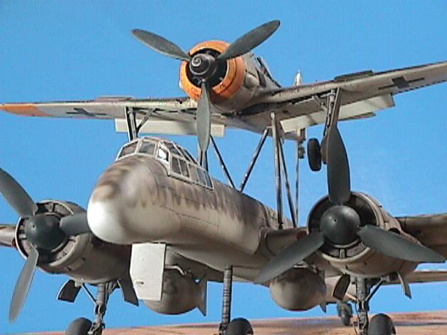
Within this environment the Mistel composite aircraft concept
was utilized to yield a project known as the Fuhrungsmaschine. The design, which
never progressed beyond the Projekt stage, consisted of an Fw-190A-8 mounted atop a
Ju-88H-4 equipped with a nose-mounted, surface search centimetric radar system. Unlike the
Misteln, however, the mission of this composite aircraft was "ultra-long"
range pathfinder duties. In this design, the Ju-88H-4 served as "mother ship"
while the parasitic Fw-190A-8 was intended to serve as detachable fighter escort.
Although never actually built, the Ju-88H-4 was development of the
Ju-88H-2 originally designed as a long range Zerstorer. Major differences between
the H-4 and its H-2 predescessor were: replacement of the H-2’s BMW 801 radial
powerplants by inline JuMos, a substantial extension of the fuselage to accommodate fuel
storage for the parasitic fighter and a redesigned nose section housing centimetric
surface search radar. Additionally, the Ju-88H-4 was outfitted with FuG 220 and radar
altimeters.
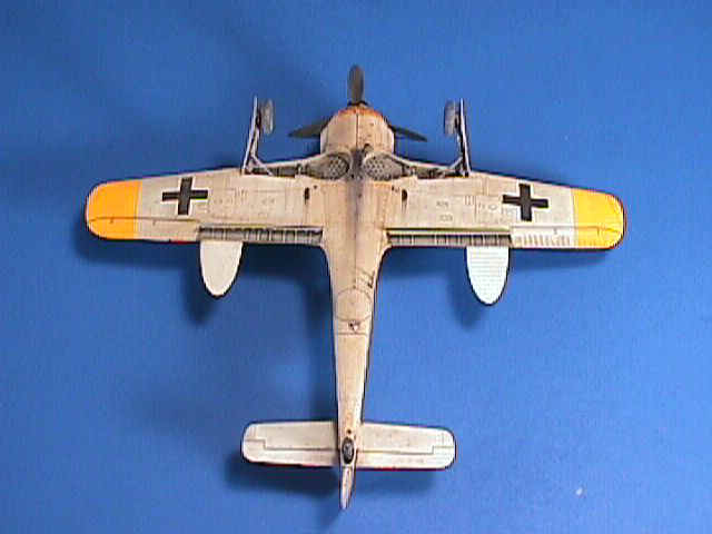
The parasitic Fw-190A-8 component as such was never actually built.
Although several configurations of Doppelreiter fuel tanks were tried on a few
early Fw-190A Versuchs aircraft, they were never adopted. On this hypothetical Fw
190A-8 aircraft, the outboard wing cannon (MG 151 20mm or Mk 108 30mm) were removed.
Construction is fairly straightforward per kit and conversion
instructions. As the H-4 fuselage build is the most complicated section, it’s
highlighted in some detail below. If not specifically highlighted, the construction is per
kit instruction.
DML’s Mistel 2/S-2 (kit 5510) was modified by incorporating the
following:
- Paragon Design’s "Fuhrungsmaschine" resin conversion set #48-047
- High Flight’s Ju-88 flap set #4836
- Kendall Model Company’s Fw-190 flight control surfaces set #48-5017
- Eduard’s photoetched Fw-190A flap set #48-011
To finish the project as described below, you will need to get hold of
the following:
- Two Jumo 213 nacelles, corresponding spinners and props (fortunately "spared"
in several of DML’s Ju-88G kits)
- Two 900 l fuel tanks (ours came from Fujimi’s Bf 110C/D),
- A second ETC hardpoint for the Ju-88H-4 (ours came from a DML Ju-88G-6). (part C1)
- Depending upon preferences, you may want to use a vac-form canopy
Construction began with the Ju-88H-4. The cockpit was built up per kit
instructions. The cockpit radar station supplied in the Paragon set was installed per
instructions. After spraying with Humbrol Schwarzgrau 66, instrument faces and
dials were painted black and drybrushed lightly with medium grey. Hoses and belts were
painted the appropriate colors. Finally, the cockpit and sidewalls were washed with
thinned black artist oils and drybrushed with RLM 02 or aluminum as appropriate.
Fuselage parts A1 and A2 were carefully separated along the panel line
immediately aft of the wing trailing edge as indicated in Paragon’s instructions.
This results in two sections, A1/A2 "forward" and "aft". After cleanup
of the various plastic and resin mating surfaces, all six of the fuselage components were
dry fit. Several minor problems surfaced here, the most significant being the aft-most
resin section was slightly smaller in cross section than the injection molded fuselage.
More on that later.
Satisfied with what lay ahead, the wing root was carefully cut out from
kit parts C17 and C18. Keep in mind the resulting holes are filled from the backside by
resin patches from the Paragon kit, so don’t overdo it when removing the roots. Dry
fit, dress, mate the resin patches to kit parts C17 and C18, fill and sand. When complete,
the sidewalls and cockpit were inserted into parts C17 and C18 as appropriate, then C17
was mated to C18 and the seams dressed as necessary. At this point, the resin nose was
attached. With this section, you will need to extensively fill the nose seam with CA and
build up the rear canopy-to-fuselage join with plastic card and CA. These fills require
lots of CA so be prepared to use low grit paper/tapes and lots of elbow grease! You will
need to rescribe nearly all the panel lines here, so take some notes BEFORE you sand!
Mate parts A1 "forward" to A2 "forward" and then A1
"aft" to A2 "aft". Now comes a little engineering fun!
Because the aircraft will be "handled" extensively, the
resin/plastic joints between the two aftmost sections required reinforcement,
specifically: A1/A2 "forward" to aft resin plug and aft resin
plug to A1/A2 "aft". To do this, four ~5" sections of 1/8"
plastic rod were inserted through the middle of the hollow aft resin fuselage section. One
rod was placed in each corner of the interior of the hollow resin plug. The rod was
centered along the corner until equal lengths extended fore and aft of the resin plug
section. This leaves ~0.5" extending fore and aft from the resin plug. The rods were
epoxied into place. Slide a ~0.75" length of 1/8" ID plastic tube over the
forward end of each rod. These are sleeves which will mount inside A1/A2
"forward". Before you can get there, however, you’ll need to buildup inside
A1/A2 "forward" (and later "aft) because the walls of the resin section are
much thicker than the plastic. Do this with multiple dry fits. Not to worry anyone, if you
don’t intend to extensively handle the model, this extensive reinforcement is not
required!
Once the buildup of the seats for the sleeves is complete, carefully
place a drop of epoxy or CA on the external portion of the sleeve, to get it to
"stick" to the seat in the injection molded fuselage subassembly. If using CA,
use 15-25 second cure as some "adjustment" may be necessary when bringing the
A1/A2 "forward" and resin plug subassemblies together. After waiting the
prescribed time, gently pull the resin section back, you should see each of the four
sleeves have pulled off the rods and are now tacked in the proper orientation on their
seats in the A1/A2 "forward" subassembly. At this point, you can add more
reinforcement or more CA/epoxy to firmly fix the sleeves.
The process just described is repeated for the aft seam joining the aft
resin plug and A1/A2 "aft". When complete, approximately 30g of lead shot was
placed inside the fuselage near the tail wheel as an insurance against having the center
of gravity move too far forward and, also, to increase the stability of the resting model.
At this point epoxy or CA the rods into the sleeves. While it sounds complicated, with
just a little patience, it will provide a strong seam that will withstand sustained
unintentional abuse. You are now down to just two pieces left to finish the fuselage.
Voila! You’ve just become an honorary structural engineer!
Finish the fuselage subassembly by mating the nose/C17/C18 subassembly
to the forward resin plug. This seam does not require any reinforcement. When dry, mate
this subassembly to the recently finished "A1/A2 forward:aft resin plug:A1/A2
aft" subassembly.
At this point you are holding a really long fuselage in your hand! You
will note there may be a 1/32" step between the "A1/A2 forward" and
"aft resin plug" seam. Remove a little plastic from trailing edge of the A1/A2
"forward" section with a file or motor tool and then build up the leading edge
of the aft resin plug with a little CA. Apply your favorite putty. With a little more work
from your motor tool or a flat metal file, you are ready to dress the seam using finer and
finer grits with your Flex-I-File and all is well with the world.
At this point, fine sand the entire fuselage, rescribe any lost surface
detail and primer the seams to scout for any subtle imperfections. In this case Humbrol
light grey was used.
After a little light sanding and touchup on the primered seams, the
vertical and horizontal stabilizers, rudder and elevator assemblies were added. A nice kit
feature is that you can offset them from neutral if desired.
Don’t forget to locate and drill a hole to accept the
"jettisonable" third main landing gear leg.
Now on to the wings! The flaps were removed from the wing section and
replaced with the High Flight resin set. Because of the way the High Flight flaps fit into
the Ju-88H-4 wing, no blinding was required. Don’t forget to open the strut locating
holes before closing the wings! Remember to swapout the BMW 801 engines and replace them
with Ju 213s. This is not a problem but a touch of putty was required. Nacelles, spinners
and propellers from the Ju-88G-6 kit were used. Antennae mounts were added at the
indicated positions under the wings.
Dry-fit the wing/fuselage join, attach them and the Ju-88H-4’s
ready for paint!
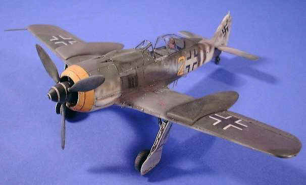
Now for the Fw-190! It was decided to replace the DML Fw-190A-8 with a Tamiya
Fw-190F-8. The kit flaps, rudder and elevators were removed. Strut receptor holes were
drilled out, the wings mated and seams dressed. The resulting "wells" in the
wing created by removing the flaps were blinded off with plastic card before an Eduard PE
flap set was installed. This area, when dry would be sprayed with RLM 02. Kendall Model
Company’s flight control surfaces were used. The rudder and elevators were offset
from neutral. Fine Molds PE belts were added to the cockpit. Exhaust shrouds absent in the
Tamiya kit were scratchbuilt.
The Doppelreiter tanks were dry fit. It was found that the
starboard tank appeared about 1/16" shorter than the port tank. After plastic stock
was added, shaped and feathered, the "fixed" overwing tanks were installed.
The ETC rack was left off because the Doppelreiter tanks
eliminated the need for a belly tank and the fighter escort role was inconsistent with a
need to carry ground-attack ordnance. Along with the outboard wing cannon, the ETC rack
might possibly have been removed to save weight. Who knows? Have fun!
P a
i n t i n g a n d F i n i s h i n g |
Unless noted otherwise, custom-blended Tamiya acrylics and Aeromaster
decals were used throughout.
First, let’s do the Ju-88H-4. Make sure you have dipped the kit
canopy in Future and allowed it to dry for at least 24 hours. After weighing the benefit
of using a thin vac-formed canopy from Squadron, vs the better fit and sharper panel lines
obtained with the kit canopy, it was decided to stick with the kit canopy. Bare Metal Foil
was used to mask the canopy. Attach the canopy to the fuselage using your favorite method.
Spray the canopy interior color, Schwarzgrau 66, over the canopy framing first. This way,
it’s visible through the "glass".
Humbrol Graublau 76 was sprayed over the dressed and primered
seams. When dry, the entire aircraft was sprayed with a second light coat of Humbrol Graublau
76. When it was dry, the aircraft was very lightly sanded with 600 grit, cleaned and
finally sprayed with Tamiya Graublau 76 and allowed to cure for 24 hours. Humbrol
is an excellent hard base coat for acrylics. The Humbrol primer treatment can be avoided
if the model is not extensively handled.
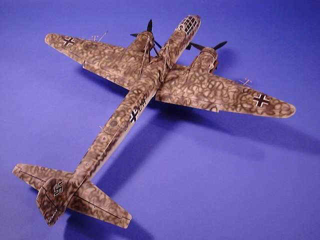
Over this was sprayed a "loose" splotch pattern of Grauviolett
75. It is reasonable to adopt this camouflage scheme as Ju-88H-2s had this finish from the
factory. These aircraft had the additional requirement for concealment on the ground.
Check your references and then wind up doing what you think looks the best! In this case a
dense squiggle pattern of Dunkelgrun 83 was used. For this to work visually, the
squiggles were tightly bound and ~1/16" wide. Although some references have suggested
squiggles were applied in several different colors, a single color scheme was maintained.
Since this aircraft was never manufactured, there was latitude for
decal options. The Werknummer was selected from a block of late Ju-88Gs. After the
project was already complete (of course!) I came across Werknummer information for
Ju-88H-2s. Geschwader assignment (i.e. selection of fuselage codes) provided the
same latitude. Conceivably one could have selected an operational unit known to have flown
Misteln such as KG200 or KG30. That would have been fine but it wasn’t known
that this pathfinder was intended solely to support Mistel operations. A more
obscure unit, KGr 806 was selected for no good reason other than to be different. In
retrospect, one might also have considered using one of the Fernaufklarungsgruppen
which were operating Ju-88s/188s. In any event, modelling should be fun, so have fun!
The aircraft was given a light wash with thinned artist’s oils.
Very light exhaust staining was added. Finally, upper wing and nacelle panel line detail
was further highlighted using a black ink pen.
In order to simulate the "newness" of the Ju-88H-4 aircraft,
it was oversprayed with clear satin to simulate the "sheen" fresh Luftwaffe
paints were reported to have (at least with the 74/75/76 schemes). This would later
contrast nicely with the severely weathered battle worn Fw-190A steed charged with its
defense!
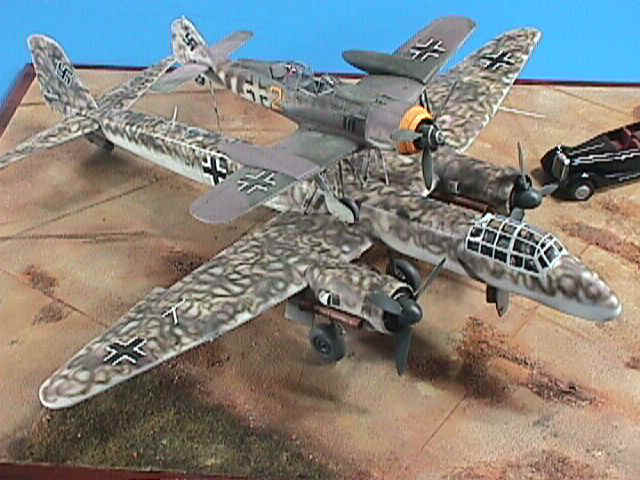
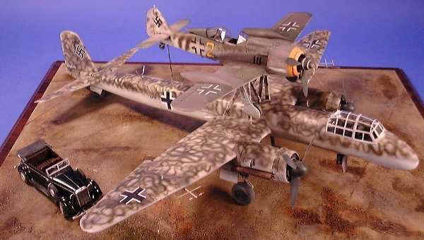
Many references agree that the mating of the Fw-190 and Ju-88G aircraft
in Misteln was done on a "whatever was available" basis. Consequently,
the fuselage codes and camouflage patterns of the two aircraft were not matched. In fact,
it was decided to exploit this to add artistic richness to the project by combining the
two "textures" which the aircraft were chosen to represent.
The Fw-190 was painted overall in a standard Graugrun 74/Grauviolette
75/Graublau 76 scheme. In order to enhance the wear and tear impression, the paints
were mixed to a much lighter shade. It was reasoned that the installation of the overwing
tanks would be a Rustsatze modification, and as such the tonal quality of the wing
and over wing tanks paints would not match. Hence, the Doppelreiter tanks were
resprayed this time using "factory fresh" color. Yellow cowl and underwing
markings were added as indicated. Additional "ground concealment" was supplied
for this fighter with a few stripes of Braunviolette 81 added along the rear
fuselage spine and continuing down the sides. This paint was blended to a "not quite
factory fresh" standard.
The aircraft was sealed with a gloss coat in preparation for the
Aeromaster decals. When the base coat was dry, the decals were applied using the
Microscale system and allowed to dry overnight. A light overcoat of acrylic flat was
applied at this point. Once dry, the aircraft was given a heavy wash with thinned black
artist oils. Extremely heavy exhaust staining was added using Tamiya’s smoke and
artist’s oils. The aircraft was left alone for 24 hours. Upper surfaces were lightly
drybrushed with white to add "wear and tear" and to bring out surface detail.
Some weathering was done using a brush and silver/grey mix around the cockpit and port
wing root area. Voila! You have one interesting looking aircraft! Finally, several
overcoats of acrylic clear flat were added and the paint left to dry overnight.
This was a very different aircraft and a very different project. The
project depicts a hypothetical aircraft which was never actually built. This had good and
bad points associated with it. The latitude the project provided for painting and decaling
was refreshing. At the same time, wanting to be reasonably "realistic" or
perhaps "probabilistic" was challenging because of the lack of a lot of
reference material. The project allowed further expression in the combination of the
"old and the new". For me it reinforced the overall impression of what
deplorable conditions existed in the Luftwaffe at war’s end.
It was fun!
Mistel, Composite Aircraft of the Luftwaffe, Schiffer
Ju-88 in Action, Squadron/Signal
AeroDetail #20 Ju-88, Model Graphix
Warplanes of the Third Reich, William Green
Model, Article
Text and Photographs Copyright © 1998 by Sam Garcia
Page Created 31 December, 1998
Last Updated 26 July, 2007
Back to HyperScale Main Page
Back to Features Page
|
 Home
| What's New |
Features |
Gallery |
Reviews |
Reference |
Forum |
Search
Home
| What's New |
Features |
Gallery |
Reviews |
Reference |
Forum |
Search