Home
| What's New |
Features |
Gallery |
Reviews |
Reference |
Forum |
Search
Home
| What's New |
Features |
Gallery |
Reviews |
Reference |
Forum |
Search
|
|
|
A Modeler's Evolution Part Five by Russell M. Field
I bought the 1/72 Academy Messerschmitt Bf 109E-3/4 because I wanted to experiment with extending leading edge slats in this scale. I'd seen extended slats on 1/48 kits, but hadn't seen it on a 1/72 model either as a kit option or scratch built. The Academy kit was therefore an inexpensive basis for a slat experiment. Besides, I wanted to build a Battle of Britain-era Bf 109 and I'd heard good things about this model (kit #2133). Among other features, the cockpit was supposedly very nicely detailed for this scale, which meant that I wouldn't have to add a lot of detail there and I could concentrate on the slats. So, really, this started out to be more of a quick build experiment on a specific feature, a happy by-product of which would be a Battle of Britain 109E.
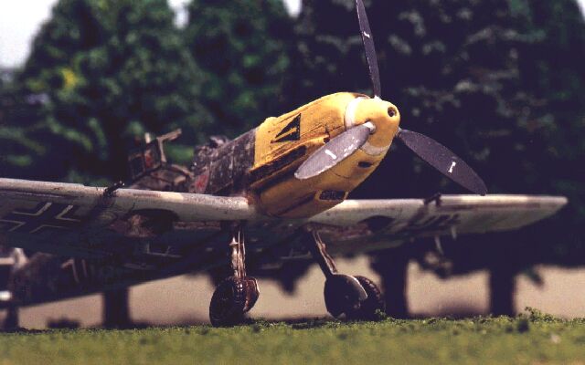
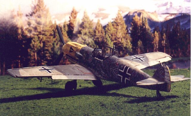
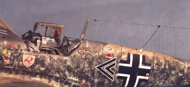
I hadn't decided which specific aircraft I would depict, so I focused on getting familiar with 109E characteristics like flap configuration and range of travel, slat design, cowl shape, and visual differences between E-3s and E-4s. Eventually I knew I would have to pick a subject and that would determine, among other things, if I modeled an E-3 or an E-4. As always, I got LOTS of help from Hyperscale visitors with questions answered, scans and references. My primary published references included the Squadron-Signal In Action book, the Profile paperback, the Arco-Aircam series, and a couple volumes from the Wings of Fame line. When I settled on Helmut Wick's plane I ran headlong into the issues of changing color schemes, incomplete documentation and conflicting sources. Seems that Wick probably had one primary plane he flew during this period. It apparently underwent at least three camo/paint scheme changes and had the rudder replaced a couple of times in a fairly short time span. Furthermore, we all know about the vagaries of interpreting black and white period photos. On top of this, it was suggested that Wick may have had one or more "loaners" that he used on occasion while his main steed was undergoing overhaul. I dived into books, magazines and decal sheets to figure out which Wick scheme I wanted. I found various errors and multiple interpretations (welcome to the wonderful world of Luftwaffe modeling!). I finally picked a scheme and went with it. I wanted a yellow-nosed bird and Wick's heavily-mottled fuselage intrigued me. I therefore picked the aircraft in early October, 1940 based on what I felt were the most reliable sources and likely conclusions. This shot attempts to replicate a photo in the Osprey book on Me 109 Aces 1939-41 (and, by the way, the whitewall tail wheel and blotchy yellow lower rudder is per a photograph in Osprey book, not an artist's rendition or wartime myth).
Academy's Bf 109E is a very decent kit for the price (about US$9 in late 1999). This kit measures out close to scale. The Hasegawa kits come out short in length. In fact, if you lay a Hasegawa fuselage half against the opposite Academy half, you might not believe that they are the same scale! The rear fuselage has an authentic shape and all the aft panel lines look right. The cockpit is nice, and the particular kit I bought offered three paint and decal schemes. Curiously, I bought another one of these a few months later, same kit number, same box art, same everything - including E3/4 options on spinner, canopy, head armor, and instrument panel - except it showed and offered only ONE subject on the instruction and decal sheets. I have no idea which kit is older, and whether Academy NOW offers three options or USED TO offer three. All in all a nice kit, but the following issues should be addressed:
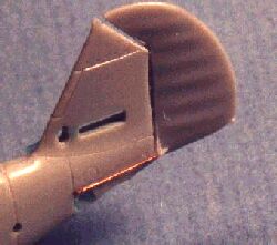
The only other real gripe I had with the basic kit was the spinner assembly design. Per the instructions, the spinner, prop and baseplate are glued to a spud, and the spud then captured when the fuselage halves are joined. Since I like to install the props after painting the fuselage (less risk of damage and easier handling), this presented a small challenge. To get around this I assembled the baseplate and spud, locked these in the fuselage and attached spinner/prop later. Fit and fair of spinner to baseplate was harder than it should have been, so I'll think a little harder on this next time (all this, of course, so the prop would turn and I wouldn't have to mask the prop!).
When the smoke cleared and the dust settled, the major features and modifications included:
Important Note: Before permanently installing the Moskit exhausts, make SURE that you've painted the adjacent surfaces. I had to know the paint scheme so I'd know what color to paint the inside of the exhaust shields before gluing the Moskits; otherwise, I woulda had to paint AROUND them - yuck!
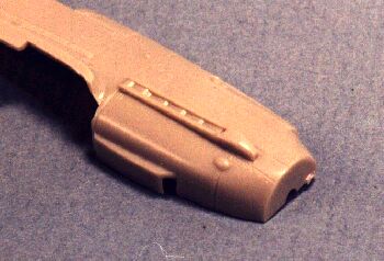
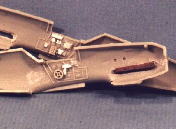
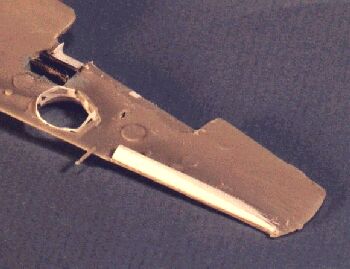
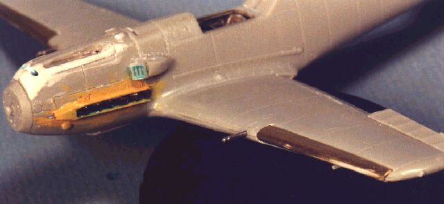
Below we see the plane almost ready for priming. The slat supports are thin styrene strips that will fit between the wing piece in the picture above and the slat; this is how the slats are displayed as extended. However, for painting I left the supports off and temporarily installed the slats to the wings so the paint job would be guaranteed to have pattern and color continuity.
The above image also shows the hypodermic-needle cannon barrel and the exhausts and supercharger masked with liquid mask. This was a mistake, folks, don't use liquid mask like this! I thought it would be quick and easy, but though it protected the masked areas it was the very DEVIL to remove from the irregular surfaces! You can also see the spinner baseplate installed sans the spinner and prop.
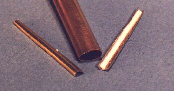
This project's big additions were the slat extension and dropping the flaps. The slats required a lot of thought, but once I figured it out they went pretty fast and easily. The flaps, however, required a lot of research, several rounds of questions on Hyperscale, and some significant rework to the underside trailing portion of the wing.
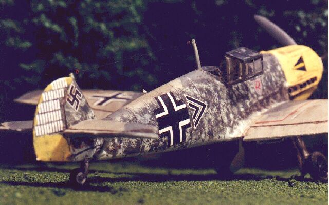
The basic paint scheme is RLM 02 Grau and RLM 70 Green over RLM 65. The cowl is RLM 04 Yellow, with the lower rudder having yellow swabbed over the heavy mottling. The fuselage sides of Wick's mount are heavily "brush-mottled" in RLM 70. One surprising issue was the upper surface pattern. There's a lot more documentation of the sides of this plane than the top. There were a couple of good guesses, and I finally went with a fairly standard splinter pattern. One reference claims the mottle extends over the RLM 02 on the fuselage spine, but I elected to leave it off those areas. The spinner baseplate was installed at this point. The tailplanes were attached, but their braces were left off to make applying the mottling easier. Also as noted, I masked some of the smaller areas with liquid mask (more on that later). I primed it with white primer, then the RLM 65 was added on undersides and fuselage sides. Standard masking procedures were used in the application of the remaining colors. I lightened the paints for scale effect, 2:1 with white, and thinned at 3:1 with Testors Acryl thinner. The side mottling, perhaps the single most distinctive feature of the plane, was applied using a "dry-dab" technique and an eye-makeup sponge. These are small, very fine-grained synthetic sponges attached to short handles. Using pointed tweezers, I pulled a few small tufts out of the sponge to make a larger pattern. The sponge surface is dipped into the paint and dabbed on cardboard or paper (don't use paper towels or tissue, as these will shed fibers) until only faint impressions come off the sponge. Then move over to the model and dab lightly on the areas to be mottled. This took a few passes, and you have to be careful at sharp edges if (like me) you haven't masked them off. I trimmed a straight edge on the sponge I used for this so I could dab right up to the sharp lines (since masking can sometimes be a pain in 1/72). When all that was done, the tailplane braces were added and the landing gear detailed and installed. The slats were removed, and the extension spacers glued on. The wing strips and spacers, covered during painting, were painted RLM 02 and the slats glued onto the spacers.
After attaching the tailplane braces, spinner and prop, I prepared the model for decals by laying down a couple of coats of Testors Metallizer sealer (thanks again, Lynn!). The decals I ended up using were from Super Scale International sheet #72-671 (Bf-109E German Aces, Battle of Britain). They seemed a little thick, but snuggled down with MicroSol. The Horrido pennant looked a little dark, but I have a nice one on an Aeromaster sheet. The Aeromaster Horrido pennant, while a nice shade of blue, was WAY too large (it fit like a horseblanket on the cowling; you can even read the "Horrido"! Another example of scale inaccuracy between models and aftermarket parts.). But even some of the SSI decals were questionable, like the victory marks on the rudder, which overlapped a little; were they too large, or is the kit rudder a smidge too small? Or both? In fact, the SSI pennant would have been too large had the cowling MG troughs not been moved up where they belong. The SSI sheet had lots of stencils, but the instructions and explanations were incomplete. On top of that, the decals themselves were unidentified by either number or letter; that is to say, the illustrations did not reference specific decals, so you had to guess at several. Neither does the SSI sheet explain options and alternatives. For example, the warning placard below the port exhausts was often partially oversprayed when cowl colors were changed (it says something like "HEY, DUMMY!! DON'T TOUCH!! THESE THINGS GET HOTTER 'N A TWO-DOLLAR PISTOL!"). The sheet offers two versions of this placard, but doesn't tell you that one represents factory fresh and one represents overspray. This absence of fundamental explanation seems to be part of the package with both SSI and MicroScale (are they the same now?). I referenced the Aircam Battle of Britain book for the stencil information (as a sidelight, this book carries a totally erroneous depiction of Wick's plane and may in fact have been the source for the MicroScale sheet, as it mirrors the Aircam description). Fading, Shading and Weathering With all the decals applied and panel lines emphasized, I sprayed a coat of Testors Acryl Flat clear. Since this plane is the subject of the Postshading with Pastels article on Hyperscale, I won't go into the weathering details here. I will let you in on a little secret, though. Remember I said the SSI sheet doesn't have location references for the decals?
Picture this... After applying a light pastel streak for the exhaust stains the weathering is almost finished. I employ various power eyeglasses for close work, and I used most powerful pair on for this.
You got it! THIS was when I realized the little dots really were letters - upside down letters! Now, who would have thought that Wick's pennant was really upside down? I never knew that before, but obviously it must be so … I mean, after all, look at the model … This is one of those "life" things that test our maturity and let us know just how far we've come as rational adult human beings … Oh, and by the way, if you look at the picture on the front of the Osprey book (the letters in the painting really are little dots!) and count the letters. You'll count six, not seven! Oh, well … the reality is that you have to be really anal retentive to catch either mistake (like I did). Final touches The aerial wires on this one are 1 lb. monofilament fishing line, lighter than the 2 lb. line I've used before. Its installation was complicated a little by the inclusion of the insulators as described earlier, but the final effect is very nice. Like the Fw 190, the wingtip navigation lights are really too small to do much with in 1/72, so I painted them white, then chrome, then clear red and green. The light on the lower rudder was left white.
Some learnings from this project:
I thought I'd throw in a few key detail emphasis points I ran across in the course of this project. Next 109E I build, I will pay special attention to the:
Since I have more than one project in work at a time, I actually sequence these articles by when a kit is finished rather than when I started it. With that in mind, the next installment will probably be a 1/72 Condor P51/1a Mustang in the experimental "dazzle" livery; BUT, it might be the Revell P51B with detailed engine; OR the JoHan/Academy 109G kit-bash I'm in the middle of; OR I might someday finish that early Tiger I tank … Article, Model and Images Copyright © 2000 by Russell
M. Field
|
 OH,
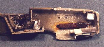
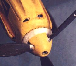
and by the way, remember the faux engine blocks? Here's a view through the upper
cooling slots - see it? How sick is that? Are there any therapists that
specialize in advanced AMS?
OH,
and by the way, remember the faux engine blocks? Here's a view through the upper
cooling slots - see it? How sick is that? Are there any therapists that
specialize in advanced AMS?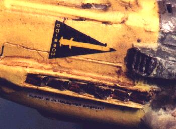 I
glanced over at the port exhausts - one of which was damaged removing the liquid
mask (figured I could write that off to "battle damage"!) - and out of
the corner of my eye I caught the Horrido pennant. Now, my eyes ain't what they
used to be, and I have to wear glasses to read, but I SWEAR to you I thought the
letters on the pennant were just little yellow dots! Since the pennants weren't
numbered for port or starboard location, I never thought about it.
I
glanced over at the port exhausts - one of which was damaged removing the liquid
mask (figured I could write that off to "battle damage"!) - and out of
the corner of my eye I caught the Horrido pennant. Now, my eyes ain't what they
used to be, and I have to wear glasses to read, but I SWEAR to you I thought the
letters on the pennant were just little yellow dots! Since the pennants weren't
numbered for port or starboard location, I never thought about it.