Home
| What's New |
Features |
Gallery |
Reviews |
Reference |
Forum |
Search
Home
| What's New |
Features |
Gallery |
Reviews |
Reference |
Forum |
Search
|
|
|
A Modeler's Evolution Part Six by Russell M. Field
Murphy lives in my model closet, and administers his laws from there. From the time I first saw the "dazzle" pattern Mustang, I knew I wanted to model it. I've seen some pictures of 1/48 models of this airplane, but I wanted to do it in my "home" scale of 1/72. The special splinter pattern was only one of the challenges, and in the end turned out to be the most simple to resolve. The list of "opportunities for personal growth" got longer as I got farther into the project, and the base kit (Condor 1/72 P51/IA, kit # C72015) spawned a couple of "projects within a project". Practically speaking, I figure I spent somewhere in the neighborhood of three months (linear time) on this one. Someday I'm going to use a stopwatch to figure out how much "touch time" I really spend on these little buggers.
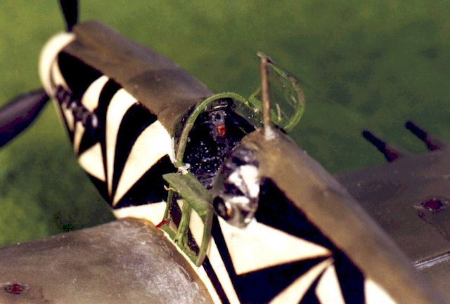
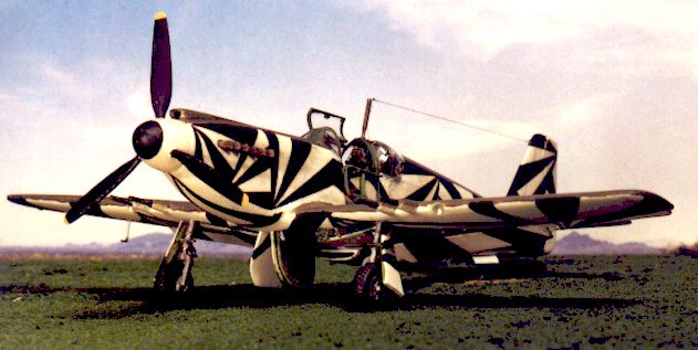
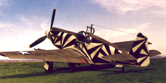
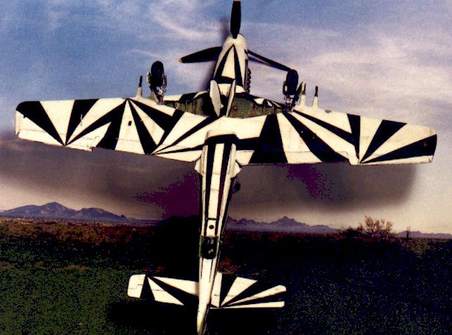
Evidently only one Mustang ever carried this black-and-white splinter camouflage pattern. It was an American P51, with the port rear canopy blister for the camera. Indication for the basic airframe type was that it most likely had a ventral camera aft of the radiator outlet as well. USAAF Capt. Paul Hexter developed this pattern in 1942. The design is similar to patterns applied to some WWI ships, the intent being to confuse the eye as opposed to hiding the aircraft by making it resemble its surroundings. The approach was moderately successful, but due to the application and maintenance effort required it was not pursued beyond this single craft. I have found no evidence of any other type of WWII airplane being adorned with any pattern like it. Once again, I got TONS of help from Hyperscalers, answers and scans and references. My primary published references included the Squadron-Signal P-51 In Action and Allison Engined Mustangs Walk Around books, the Profile paperback, #5 of the Aircam Aviation series (North American P-51B/C Mustang in USAAF Service), the P51 Detail & Scale vol. 1, and volume 1 from the Wings of Fame line. The In-Action has one picture of the actual bird, and the Aircam book shows that and one other photo; the Profile and Walkaround have drawings of it. I was referred to an Osprey book on P51s that shows an in-flight underside shot of this bird and a port-side shot in the work hangar. These are the only photos I could find. The first two pictures in this article attempt to imitate those found in the SS and Profile volumes.
In choosing a baseline 1/72 kit, I considered backdating the Revell/Germany P-51B (with its fairly correct wing, decent interior and acceptable wheel wells) or going with another kit that targeted the earlier Mustang features (upper cowl intake, no chin scoop, etc.). I finally decided to go with the Condor P-51/1A kit at about US$10, coupled with a True Details P-51B cockpit set and resin wheels. In hindsight, this may be the best 1/72 kit for this project but I was a little disappointed. It seems to measure out fairly close dimensionally, but:
The major features and modifications included:
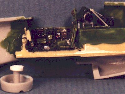
The mirror and ring sight may be minute detail touches, but they add a nice look in my opinion. The True Details cockpit set apparently reflects the later radio location after a fuselage fuel tank was added. To accommodate the camera I had to move the radio aft; in modeling any pre-B/C Mustang, I assume this would be appropriate. I ended up using the kit canopy instead of a vac-form piece because its extra sturdiness made the blister installation more secure. The camera body was made from half-round and channel stock, the lens from two diameters of rod.
The dried mold was then glued to the end of a wooden dowel and several thin coats of superglue were applied, allowing each to cure fully before the next was put on. This gave a hard surface that could be final shaped with a file and polished to a very smooth finish so as to minimize flaws in the blister. Finally, the blister was plunge-formed using .010" clear, flat plastic sheet from a plastic package cover; it took about six or eight tries, but I finally got a good one out of it. The lens bezel is from a Reheat instrument bezel fret; the kit window was carefully removed and the blister was fitted, then attached with thin lines of window cement.
Wings and Landing Gear
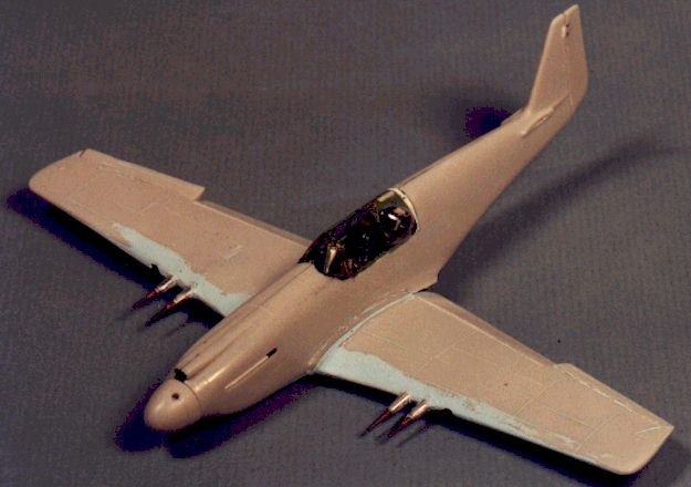
The cannons and their fairings were made from telescoping aluminum and hypo tubing. Two sizes of aluminum tubes were glued together and shaped on a motor tool, with the hypo tube as the barrel. Fine wire from an old set of CD player headphones was wound around the barrel base to simulate the recoil springs. The inboard flap ends needed some putty and shaping to simulate the way the wing root overlaps them on a real Mustang. Here's the plane almost ready for masking and priming, minus the tailplanes and radio mast:
OOOPS! You'll notice a white spacer behind the canopy; I originally fitted a vac-form canopy - which was a tad longer - and later decided to use the kit piece, necessitating the spacer!
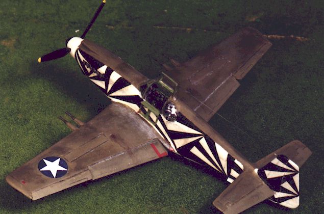
The basic paint scheme is olive drab over white fuselage sides and undersurfaces. The bugga-boo, of course, was the black splinters. HyperScale to the rescue!! I made a couple of posts asking for suggestions, and one of the "regulars" sent me a scan of a 1/48 decal sheet (origin unknown) with the splinter pattern. Since this sheet is not available in 1/72, I don't think there's any legal issue here but for safety's sake I won't reveal my source - hey, maybe I can get a job with the Washington Post? I took the scan and upped the contrast to get rid of the blue background (the sheet paper is blue). Then I printed it, reduced it and took the 1/72 master sheet to a local copying shop along with some clear decal material (Expert's Choice). I what I wanted to do; they checked the material, set their machine and ZIPPO! I had two excellent 1/72 decal sheets of the dazzle pattern! This stuff has proven impervious to water, solvents, paint, etc. There are four decals on each side of the plane and twelve or fifteen on the underside - I'd say ~75% of the model's surface is covered by decals. I masked and primed the plane and painted it white all over. The fuselage splinter decal outlines were cut from a paper copy of the sheet and laid on the plane; the upper edges were then lightly traced to establish the OD/white demarcation line. This line was then masked and the OD sprayed on. Only minor touch-up was required after the decals were applied.
Murphy checks in … The only other decal on the plane is the national insignia on the upper port wing. I started out with a star from the Condor kit, which has the lighter blue surround. AFTER (of course, AFTER) I was almost done, I decided that color just wouldn't do. I tried fixing it, but to make the story short I carefully scraped it off and replaced it with a darker insignia from another sheet. Now, when I scraped this thing off I discovered just how thick a covering was on the wing: 1 coat of primer, 1 OD, 1 gloss, and 2 clear flat. The result was a dime-sized divot in the surface, which would leave the new decal noticeably lower than the surrounding area. SO … I filled the area with four or five coats of OD paint (unthinned), let it cure and carefully polished it down to surface level (the two clear flat coats kept the original surface intact). I applied the new decal, faded it slightly and applied one more clear flat overcoat. Viola! All better now …
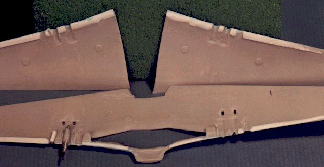
Also take note of the corrected wing leading edge.
Many of the P-51 models I've seen emphasize the panel lines on the upper wing surfaces. Yet, based on several HyperScale threads and references, this appears to be inappropriate. I decided to fill in the recessed panel lines on the upper wings and the forward half of the lower wings to simulate the smooth surfaces of the laminar-flow Mustang wings (I'm sure someone will comment!). As an experimental unit, one would expect this plane to be relatively clean (if a bit worn - one of the published photos shows fairly heavy wear on the port wing root). All upper surface fading and shading was done with pastels, as was the application of very minor gunpowder and exhaust stains. Faint fuselage panel line grime was also depicted with light-colored pastel dust. The fuel stains around the wing tank caps come from application of a drop of dark brown watercolor wash, drawn down and back with a small brush. The center area of the stains was lightened using a small swab moistened with water to remove some of the wash.
The propeller blades were painted, glued in place and touched up as needed. The landing gear were painted, brake lines added and then the legs attached to the fuselage with the appropriate rake and track using regular plastic cement, again for added strength. The wheels were painted, then fitted to the gear. Then Murphy checked in again to see how things were going …
What we do for the little things … The aerial wires are 1 lb. monofilament fishing leader. The wingtip nav lights (upper and lower) were painted white, then chrome, then clear red and green. You may notice there is no light on the spine near the radio mast; I've seen that light on a couple of 1/48 representations of this plane, but I can't see any indication of it on the one picture I have where this area is visible. It may have been standard equipment on P51/1A's, but on this particular plane I can't find it. The canopy doors were detailed, painted and attached with white glue. The port door especially shows some sheet and wire detailing; both were dipped in Future and allowed to dry before painting. Oh, yeah, the landing lights. I picked a size of clear (silver) MV lens that would pretty much fill the landing light opening and glued them in on a downward angle using Goop adhesive. I then filled in the sides with Testors window cement and smoothed to the leading edge contour. Finally, when the window cement was cured I smeared a dot of Future on the lights.
Some learnings from this project: Altering the exhaust stacks so they could be mounted from the outside really simplified the whole painting and decaling process, as did delaying the propeller blade installation; I'll keep doing this where I can. This is the second project in a row that the kit canopy has proven more suitable than vac-forms … maybe there's a message there somewhere … This was the first kit I've built where the canopy included part of the fuselage. Puttying and smoothing the joint so it looks seamless and then masking for the painting was a bit of a challenge (I need to work on my canopy masking in general!). On applying decals: the Expert's choice decal material is fairly thin. I'd gotten into the habit of using MicroSet to wet the model surface, but these decals were difficult to position. After some advice from another Hyperscaler, I got back to basics and used plain water to wet the surface and float the decals into position. Works like a charm; maybe that's why modelers have used water for so many years … When the splinter pattern master was done for the decals, I failed to notice a slight "pixelization" (hey - is that a word?) of some of the edges (small "stair-steps" caused by the resolution level of the screen and printer). What I SHOULD have done was use a black pen and straight edge to clean up the master, then re-make the decals; what I DID was clean up the DECAL sheet with a "permanent" Sharpie marker, then applied the decals per normal. I wanted to use Testors Metalizer sealer to gloss over the applied decals so I could wash the fuselage panel lines, but something made me grab a junker, ink it up and spray some sealer on it … YAHOOO!!! The ink ran like a wild animal; the Metalizer sealer DISSOLVES this "permanent" marker ink! I ended up using Testors Acryl clear gloss instead. On photography: Being frustrated with my scanner's tendency to darken a photo, I experimented with over-exposure by taking two shots of each "pose", one on the automatic settings and the next with the manual setting one stop over-exposed. Ideally, this would have given me one good pic and one lighter shot that could be scanned without becoming too dark. What I got was inconsistent color on some of the shots; it's beginning to look like I'll have to pick the settings and stick with them for an entire roll. ALSO … note the background on the scenic shots - that's the top half of a picture from a golfing calendar!
A few detail points I ran across in the course of this project. Next pony I build, I will pay special attention to the:
Not sure what the next instalment will be; I REALLY need to do a couple of kits right out of the box. BUT, I do have that Revell P51B with detailed engine in work; AND a JoHan/Academy 109G kit-bash; there's that 70% done Tiger tank, the 40% Airacobra, and Stuka I've wanted to get into …
Article, Model and Images Copyright © 2000 by Russell
M. Field
|
 Cockpit
and Canopy
Cockpit
and Canopy
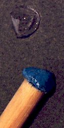 The blister
was made by molding a small piece of PlayDoh on the rear port window of the kit
canopy to what I thought the blister shape should be (pictures of this feature
are rather sparse, at least in my library). This piece was then carefully
removed and allowed to air dry for several days; I have found that oven drying
small bits like this is faster, but more likely to result in deformation.
The blister
was made by molding a small piece of PlayDoh on the rear port window of the kit
canopy to what I thought the blister shape should be (pictures of this feature
are rather sparse, at least in my library). This piece was then carefully
removed and allowed to air dry for several days; I have found that oven drying
small bits like this is faster, but more likely to result in deformation.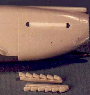 Fuselage
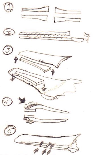 The
wing leading edge was a big issue. I corrected its shape by (refer to the
accompanying process sketch):
The
wing leading edge was a big issue. I corrected its shape by (refer to the
accompanying process sketch):
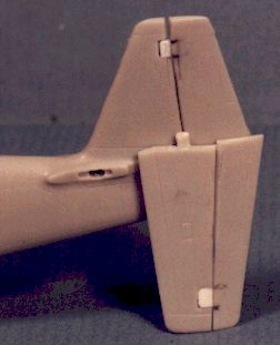 Another
issue is the tailplane tabs; this compromises the strength of the joint.
Fortunately, the sprue attach points are dead center on the locating tabs.
I cut the attach point long, including part of the sprue, and shaped it
into a longer tab. I then drilled locating holes in the fuselage, fitted
the pieces, and used regular model glue to attach them (this stuff
actually melts the plastic surface, yielding a stronger bond in many cases
than superglue).
Another
issue is the tailplane tabs; this compromises the strength of the joint.
Fortunately, the sprue attach points are dead center on the locating tabs.
I cut the attach point long, including part of the sprue, and shaped it
into a longer tab. I then drilled locating holes in the fuselage, fitted
the pieces, and used regular model glue to attach them (this stuff
actually melts the plastic surface, yielding a stronger bond in many cases
than superglue).
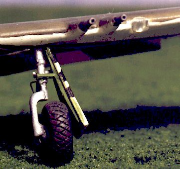 When I
laid the landing gear doors on the legs, they exposed more of the wheel hub than
I wanted. I found several pics of fully exposed hubs, but I wanted this one to
look loaded and ready to go. It wasn't that the doors were too short, rather
that the gear legs were too long (based on the angle of the oleo scissors). So
after some thought, out came the nippers, clipping the legs right next to the
fuselage. I marked the required depth on the legs with a soft pencil, drilled
out the mounting stub on the wing and re-fitted the legs. Once again these were
attached with plastic glue and allowed to set up before anchoring the brake
lines and adding the doors and brackets.
When I
laid the landing gear doors on the legs, they exposed more of the wheel hub than
I wanted. I found several pics of fully exposed hubs, but I wanted this one to
look loaded and ready to go. It wasn't that the doors were too short, rather
that the gear legs were too long (based on the angle of the oleo scissors). So
after some thought, out came the nippers, clipping the legs right next to the
fuselage. I marked the required depth on the legs with a soft pencil, drilled
out the mounting stub on the wing and re-fitted the legs. Once again these were
attached with plastic glue and allowed to set up before anchoring the brake
lines and adding the doors and brackets.