|
De
Havilland Mosquito |
"Our
Flight Will Be Delayed by JG 5..."
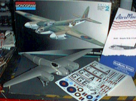
Mosquito BOAC Airliner
A
Mosquito FB VI Airliner from the Monogram kit, Part 1.
by Mike Still
|
De
Havilland Mosquito |
I n t r o d u c t i o n |
In my Mosquito XIX article, I outlined the Monogram kit’s dimensional problems - tail height and fuselage width. Sure, they may be problems, but they are also opportunities to exercise your plastic cutting skills.
Just fixing the tail on the XIX made a major difference in the kit’s looks, and broadening her beam is well within the capabilities of the aspiring kitbasher.
B a c k g r o u n d |
I saw the Mosquito airliner photo in Bill Sweetman and Rikyu Watanabe’s Mosquito book when I started the XIX in 1997 (guess that project sat in the "in-progress" shelf awhile!), and I decided it would be a neat piece in the future.
The future came when Colin Ritchie informed me of Aeromaster’s out-of-print Mosquito sheet with a BOAC airliner modification a month ago, and I thought it would be a great opportunity to try stage two of a corrected Monogram Mossie.
BOAC, according to Sweetman, operated an early, short-nacelled PR Mossie and 12 modified FB. VI’s for the "ball bearing" run to Sweden between 1942 and 1945. All 13 birds were unarmed, and accommodations were made for four passengers in addition to the two-man flight crew. High-quality Swedish ball-bearings were a frequent return passenger to the BOAC terminal.
Over 500 runs were flown in the three-year period, and four Mossies were lost. The title of this article refers to one potential obstacle to a safe flight - Jagdgeschwader 5 "Eismeer" (Polar Sea Wing), which deployed some of its staffeln in the Scandinavian regions for much of the war.
Even though much of this discussion is moot, given the arrival of the Tamiya quarter-scaler FB VI/NF II, the Monogram kit still is the only game in town for a 1/48 B Mk. IV or PR mark - at least until some enterprising resin manufacturer makes a new nose for the Tamiya kit or Tamiya does it themselves.
So let’s look at part one of tearing up a perfectly marginal but classic kit . . .
B r o a d e n i n g T h e B e a m |
 Some up-front
warnings: This is a cosmetic job, and I believe the Airfix article called for a 1/8"
widening of the fuselage. I only went with an .040 styrene spacer on this conversion, but
an eyeball comparison with the Revell 1/32 Mosquito fuselage shows that .040 inch looks
pretty close. Technically, the wingspan should be adjusted for the increase in fuselage
width, but the radiators and nacelles would have to be brought back toward the fuselage
somehow. A dry fit of the kit parts showed (to me, at least) that it made little
difference in the overall appearance.
Some up-front
warnings: This is a cosmetic job, and I believe the Airfix article called for a 1/8"
widening of the fuselage. I only went with an .040 styrene spacer on this conversion, but
an eyeball comparison with the Revell 1/32 Mosquito fuselage shows that .040 inch looks
pretty close. Technically, the wingspan should be adjusted for the increase in fuselage
width, but the radiators and nacelles would have to be brought back toward the fuselage
somehow. A dry fit of the kit parts showed (to me, at least) that it made little
difference in the overall appearance.
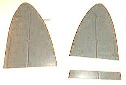
So, if you dare, first cut off the fin and rudder from each kit and shorten the parts per the description in the NF XIX article (Photo 1). If you want to build a bomber, leave the Monogram bomber nose in place. Obviously, for a fighter conversion, cut away the molded-on nose. To do a bomber you’ll also have to widen the kit clear nose piece and bomb aimer’s floor, and mold a new piece. Now you see why I’m doing the fighter/airliner!
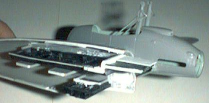
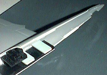 Next, cut away all
fuselage locating pins except the rearmost tail cone pin. Get some .040 styrene strip
(.040x.040 will work best here for handling reasons). If you look at photo 2, you’ll
see that I tapered both sides of the strips starting 3" aft of the cockpit opening on
the dorsal area and 1 5/16" aft of the bomb bay doors on the ventral strip. The upper
strip is then glued in place from the cockpit rear to the front of the fin fillet, and
flush with the exterior of the fuselage. The ventral strip is glued from the front back to
the front of the tail wheel well, also flush with the exterior.
Next, cut away all
fuselage locating pins except the rearmost tail cone pin. Get some .040 styrene strip
(.040x.040 will work best here for handling reasons). If you look at photo 2, you’ll
see that I tapered both sides of the strips starting 3" aft of the cockpit opening on
the dorsal area and 1 5/16" aft of the bomb bay doors on the ventral strip. The upper
strip is then glued in place from the cockpit rear to the front of the fin fillet, and
flush with the exterior of the fuselage. The ventral strip is glued from the front back to
the front of the tail wheel well, also flush with the exterior.
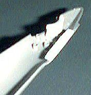 Trim away the excess
strip inside the halves, and super glue one-inch pieces of wide .020 strips in strategic
places for new locators. Don’t forget to bend the locators a little so one fuselage
half doesn’t spread and form a step on the joint later. Also, add a shaped styrene
spacer from .060 sheet to fill the now-gaping fin root (Photo 3).
Trim away the excess
strip inside the halves, and super glue one-inch pieces of wide .020 strips in strategic
places for new locators. Don’t forget to bend the locators a little so one fuselage
half doesn’t spread and form a step on the joint later. Also, add a shaped styrene
spacer from .060 sheet to fill the now-gaping fin root (Photo 3).
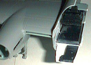
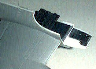
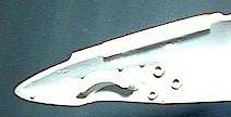 Photo 4 shows the
mud guard that goes in the tail wheel well. I made this from a curled styrene strip roof
and sheet sidewalls glued with Tenax and trimmed to shape when dry.
Photo 4 shows the
mud guard that goes in the tail wheel well. I made this from a curled styrene strip roof
and sheet sidewalls glued with Tenax and trimmed to shape when dry.
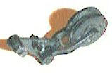 The kit tail wheel unit is
marginal, but using the magic Dremel (Photo 5) to hollow out the yoke and grind the
anti-shimmy tread into the tire makes the part look pretty good.
The kit tail wheel unit is
marginal, but using the magic Dremel (Photo 5) to hollow out the yoke and grind the
anti-shimmy tread into the tire makes the part look pretty good.
 The cockpit floor
also has to be widened (Photo 6). I thought an .020 strip on each side of the part would
work, but it wasn’t enough. Actually, glue .040 strips to each side, and dry fit and
sand until the fuselage halves fit together.
The cockpit floor
also has to be widened (Photo 6). I thought an .020 strip on each side of the part would
work, but it wasn’t enough. Actually, glue .040 strips to each side, and dry fit and
sand until the fuselage halves fit together.
If you’re going to open the access door and want an accurate cockpit interior, you will have to lower the forward cockpit floor. I first cut away the forward floor level from the bomb bay piece. I then divided the navigator’s and pilot’s sides with a VERTICAL cut, leaving a section with the mounting hole for the instrument panel.
 A new port floor was
cut from .010 plastic sheet and glued on the underside of the vertical section of the kit
floor and the mounting hole (Photo 7).
A new port floor was
cut from .010 plastic sheet and glued on the underside of the vertical section of the kit
floor and the mounting hole (Photo 7).
 A piece of .080
styrene bar was glued to the back of the new floor, allowing the floor to be glued below
its original level on the bomb bay unit (Photo 8).
A piece of .080
styrene bar was glued to the back of the new floor, allowing the floor to be glued below
its original level on the bomb bay unit (Photo 8).
The kit cockpit is pretty terrible overall, so break out the Dremel tool and grind away the support for the navigator’s seat. Carve and sand a new seat cushion from .020 styrene, and add a new seat back from styrene using the many references on the market (I used the cutaways in the Sweetman-Watanabe monograph).
Things get hairy at this point. I wanted a fairly flush cockpit wall to detail, but the Monogram kit root is prominent inside. So . . . . assemble the wings and landing gear per kit instructions. Detail the radiators in your favorite method, and open the underwing holes for the slipper tanks (although I’m sure BOAC pilots would had loved to have rockets . . . .). BUT be sure to leave the tanks off until after decaling. Trust me on this one.
Be sure to cut away the main gear axles and bore out the axle sockets to take styrene rod or aluminum tube axles. Also, fill, file and sand any seams in the wing half joints (and there are plenty) with super glue and accelerator. Thin down the trailing edges too.
Mill out the carburetor intakes , if you’re brave or foolish enough (I was foolish enough, since I’d done it on the NF XIX). Finally, add .040 strip caps on the end of each locator tongue on the wings to compensate for the earlier fuselage work
Attach each wing to
its respective fuselage half and break out the Dremel tool again. Using small steel ball
cutter and glass etching bits, I milled down the radiator roots so the cockpit walls were
continual surfaces (Photo 9). Be careful not to cut through the roots, though. Some of the
interior wing socket will be left, but the radio shelf part hides most of this. Finish out
the smoothing with putty and sanding sticks, and reinforce the wing-fuselage joint around
the radiator from the outside with super glue and accelerator.
The cockpit opening is also wider, now that you’ve shimmed things. To avoid the canopy falling through the hole, securely super-glue more .040 strip around the opening. Shape this to fit the outer and inner contours.
S t a c k s |
The BOAC option in the Aeromaster sheet requires one more bit of surgery - exposed exhaust stacks.
This may not be for the faint-hearted, and it certainly was a moment I’d been happy to avoid for the last 20 years. But now’s the time, and a little suffering is good for the soul - especially when you can read how not to do it!
Now that you’ve got the wings assembled and finished, it’s actually a good time since you can compare and align the stack openings on both nacelles. Cut slots in the exhaust shroud mounting area, about 5 mm aft of the cowling front and 1.XXXX cm toward the rear. These slots should be about 3.5 mm fron top to bottom, also.
Since the spinners and backplates are not installed, glue pieces of styrene block behind the slots for mountings for the stacks. Remember that the mount surfaces should be parallel to the thrust line, not flush with the backs of the slots!
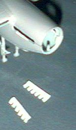 You can cadge some
useful stacks from a Monogram 1/48 P-51D (not B), since the kit contains the stamped metal
units and the more defined individual ejector stacks suited to this project. I tried
cutting and bending new stacks from plastic tube, but I just don’t have the eye for
it. Instead, I milled out six-stack units from solid styrene blanks with a Dremel tool and
fine bits (Photo 10). It probably is harder, but I was happy with the results. Install
whatever stacks you use and breathe a sigh of relief, because you’re over the hard
part.
You can cadge some
useful stacks from a Monogram 1/48 P-51D (not B), since the kit contains the stamped metal
units and the more defined individual ejector stacks suited to this project. I tried
cutting and bending new stacks from plastic tube, but I just don’t have the eye for
it. Instead, I milled out six-stack units from solid styrene blanks with a Dremel tool and
fine bits (Photo 10). It probably is harder, but I was happy with the results. Install
whatever stacks you use and breathe a sigh of relief, because you’re over the hard
part.
Add strip around the instrument panel to fit the new interior. I chose to keep the kit part, but I ground out the plastic around the rudder pedals. It looks a lot better.
The fighter nose part needs all its gun ports and troughs blanked off for the BOAC
airliner. Next, dry fit the fuselage halves together with masking tape and place the nose 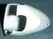 to see where the nose width
is narrower than the new fuselage. Mark that area with a pencil or marker, and cut new
cheek pieces with .020 or .030 sheet (Photo 11). For an open access door, I cut open the
hatch before adding the cheek pieces, and reopened the hatch afterward.
to see where the nose width
is narrower than the new fuselage. Mark that area with a pencil or marker, and cut new
cheek pieces with .020 or .030 sheet (Photo 11). For an open access door, I cut open the
hatch before adding the cheek pieces, and reopened the hatch afterward.
Don’t putty and sand the nose to shape until after you’ve attached it permanently.
I had no information about passenger accommodations on the airliner Mossie, other than that the bomb bay seated four uncomfortably, so I didn’t go into that area.
Now that you’ve gotten this far, you can see that it should go together. Most of the work is easy stuff that you’d have to do to make the Monogram kit look halfway decent anyway. So take a breather and wait while I finish the rest of this ritual mutilation!
To be continued...
Back to HyperScale Main Page
Back to Features Page