Home
| What's New |
Features |
Gallery |
Reviews |
Reference |
Forum |
Search
Home
| What's New |
Features |
Gallery |
Reviews |
Reference |
Forum |
Search
|
|
|
Scratch Building a P51-A Mustang Wheel Well by Russell M. Field
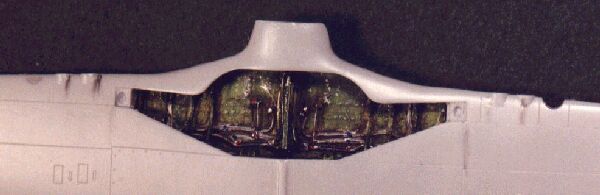
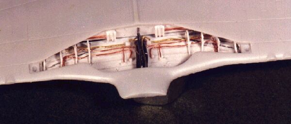
The first time I saw pictures of the P51/1A sporting the experimental "dazzle" paint scheme, I knew I had to build one. I spent some time looking for a suitable kit, and considered backdating one of the newer 1/72 P51-B/Cs from Revell/Germany. Ultimately, I bought a Condor kit on someone's recommendation (Hi, Rich … we need to talk … ). The rest of that adventure will be told another time; suffice it to say that the 1/72 Condor P51/1A kit is not one I would choose again. As evidence of it's overall condition, here's the way the wheel well ceiling looked straight out of the box (note also that the leading edge is more "D" than 1A, and is short on landing light openings; that gets fixed too, but not here):
Of course, such an ugly orifice could not be allowed to coexist with the rest of my pet project. Sometimes I just can't leave well enough alone (get it? Leave "well" enough alone? WHEEL wells? Get it? HAW!!).
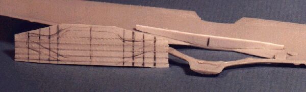
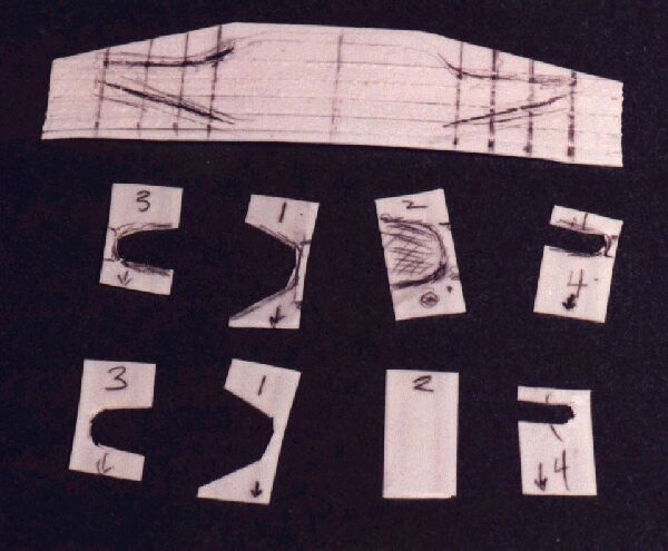
After some research and thought about how to approach improving this situation, I decided that I could get the effect I was after with two subassemblies - a new main wing spar section and a new wheel well "ceiling". I removed the kit wheel well ceiling with a Dremel saw blade (leaving the landing gear attach points; talk about an oversight that would have REALLY p***ed me off, especially since gear installation is one of the last things I do!). I then cut and rough-fit the ceiling from .010" sheet and the spar section from .040" stock, marking them for centerline, well openings, seams and web locations.
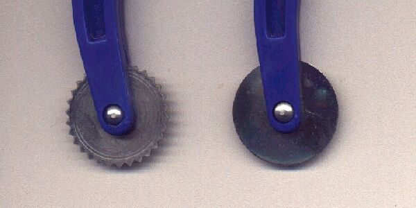
You may notice the embossed seams and rivet heads on the ceiling piece. This was added by laying the piece on a wooden board (the backing has to be firm, yet soft enough to let the styrene deform a little) and running a smooth tracing wheel (available at fabric stores) along the seam lines, guided by a steel rule. The ceiling piece was then turned over, and on the side that wasn't going to show I ran a toothed tracing wheel just to one side of the seam ridges. This pushed little hills of material into the wooden board. Since the teeth are about 3/32" apart, for 1/72 scale I had to make three passes for each seam, repositioning the teeth each time. I had considered using a sharp-pointed ponce wheel, but I think that would make holes in the styrene rather than indentations. Here's a picture of the tracers:
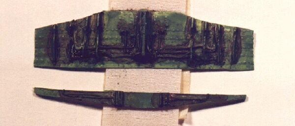
The wheel well webs were roughed out of .010" sheet, with the cutouts located and sized according to the well opening at each web's assigned position. Note the "buttock line" numbers on the webs in this picture; that's to help me keep track of which one goes where (there's a 1 left and 1 right, 2 left and right, etc.). The webs are shown in various stages. The arrows helped me remember which end went to the aft side since the cutouts for the gear legs are offset from center. And yes, you observant little bugger, the arrows on webs 3 R & L are pointing the wrong way; luckily I caught that before I glued them on!
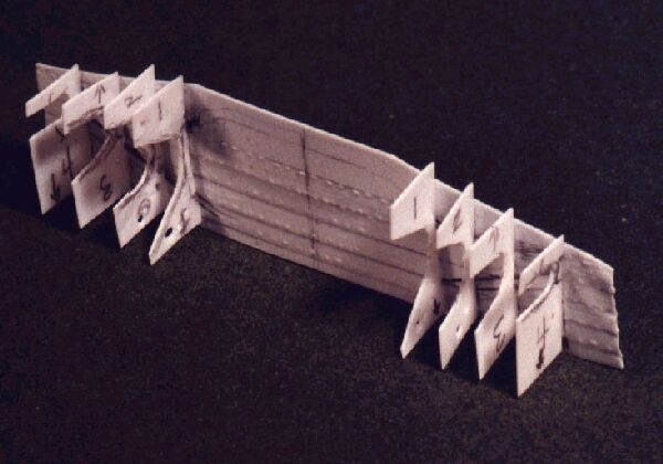
After roughing out the webs, several holes (itsy bitsy holes) were drilled in the spar, webs and ceiling for the service lines. This would have been MUCH easier and faster (especially in the webs) with a set of miniature punches, such as the Waldron products; guess what one of my next major purchases is gonna be. The webs were then attached to the ceiling with thin superglue in preparation for final fitting. Each web was held in tweezers and one end of the edge that would contact the ceiling was dipped lightly in a drop of glue. The web was then positioned on the ceiling at the appropriate line, holding it in place briefly until the CA set up. I then used a needle point to deposit a thin drop along the rest of the edge. Starting with the inboard webs and working outboard made it easier as well.
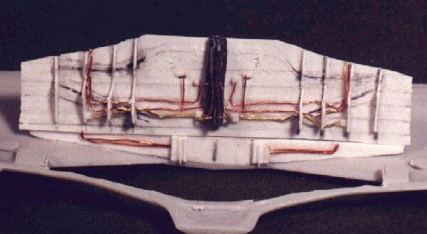
The spar section also had some details attached; after final fitting it was temporarily attached to the wing with white (Elmer's) glue to aid in final fitting of the ceiling. Using different diameters of lead, brass and copper wire for the service lines, the ceiling and spar section were rigged and final fitted. The keel section running down the center of the ceiling is a piece of trimmed styrene "I" beam; the bracketry on the spar is channel stock with a sliver of .005" sheet glued in.
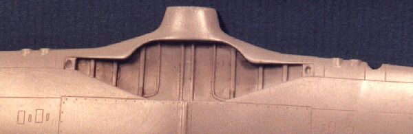
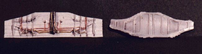
Just for grins, compare the scratch ceiling at this stage with the kit ceiling:
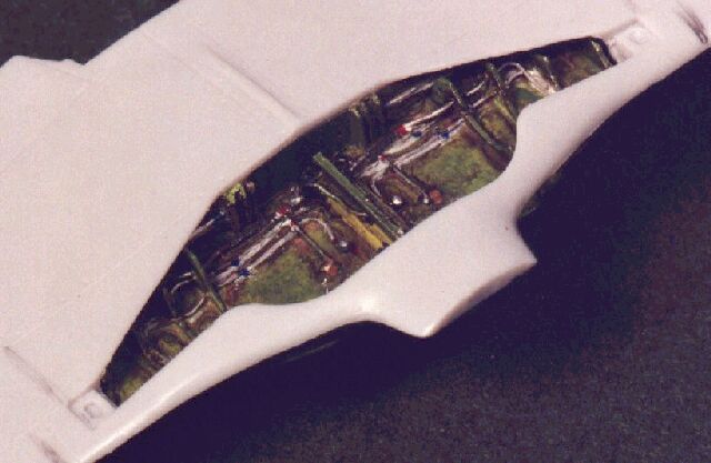
Here we see the final fitting and temporary installation (again, with white glue) of the new components:
Some of my favorite pictures in scratch-building articles and books are those showing all the different materials like this. Someday I may just build a whole kit like this and leave it unpainted!
Now for the final steps. The ceiling and spar were primed, then sprayed with Testors Model Master Acryl Interior Green. This was followed with a grungy black-brown water color wash (I shoulda gloss coated it first - darn! But sometimes I get so excited …).
After wiping off excess wash, the lines and fittings were painted with a tiny brush and a .013" stylus (AKA a broken #80 drill bit set in a wooden dowel). The metallic blue and red fittings are Model Master Clear Red and Clear Blue touched onto spots of Chrome paint. Here we see the new components finished and temporarily installed in the wing:
This little project-within-a-project took longer in conception and planning than it did to actually build. However, I find that the more things like this I attempt, the less time it takes me since I'm building an experience and technique base. Is the new wheel well entirely accurate? No. Is it MORE accurate than the kit molding? Yes. Is it better-looking than the kit molding? I like to think so! Was it challenging, fun and more satisfying than just painting the kit well? You bet! So THERE, detail police! With just a little imagination and ingenuity, a few scraps of wire, sheet and sprue you can dramatically improve the impact of your modeling efforts! Article, Model and Images Copyright © 1999 by Russell
M. Field
|