Home
| What's New |
Features |
Gallery |
Reviews |
Reference |
Forum |
Search
Home
| What's New |
Features |
Gallery |
Reviews |
Reference |
Forum |
Search
|
|
|
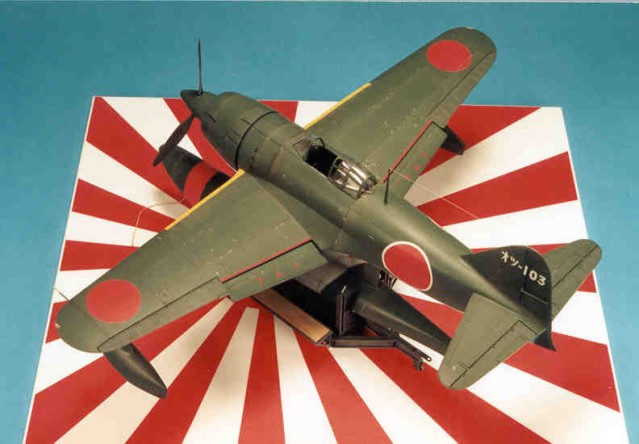
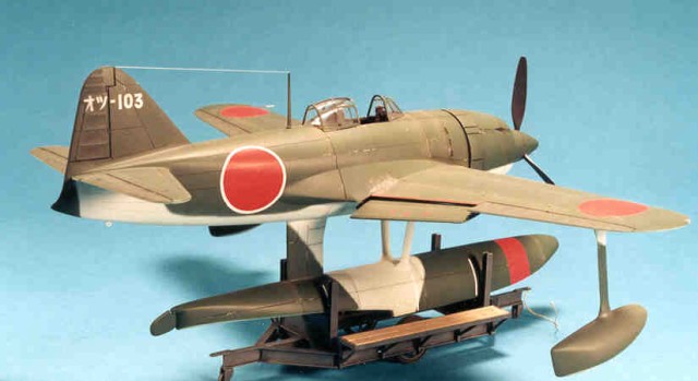
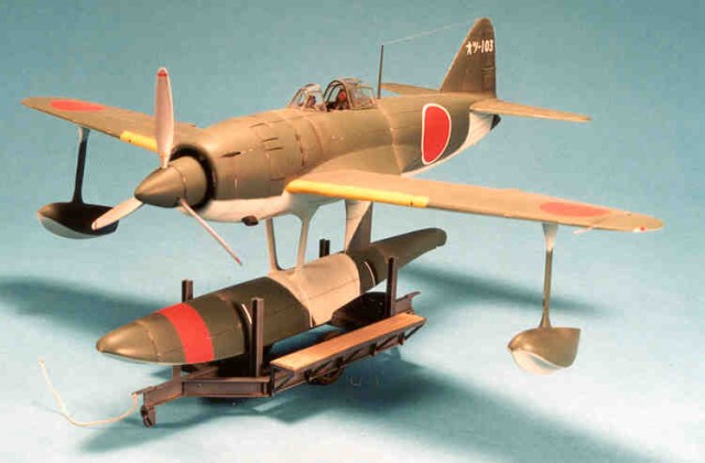
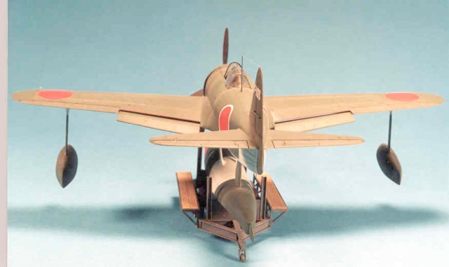
Kawanishi NiK1 Kyofu "Rex" by Randy Lutz
Combining the Scratchbuilders 1/32nd scale resin conversion set of the Kawanishi N1K1 Kyofu "Rex" and the Revell/Takara Kawanishi N1K1-J Shiden "George" to represent the Rex flown by Lieutenant Yasushi Kuwashima, the Hikotai leader of the Ohtsu Kokutai, while based at Lake Biwa in Japan during September 1944.
During 1940, the Imperial Japanese Navy recognized that there would be an impending conflict with the United States in the Pacific theatre. As a means to address this perceived conflict, a requirement was tendered for a float plane fighter. An interim aircraft was already in the works, this being the Nakajima A6M2-N "Rufe", but it was apparent that there was a need for a sole purpose-built floatplane and not the stopgap modification currently proposed. Kawanishi responded with a prototype design powered by a 1,460 hp Mitsubishi MK4D Kasei 14 engine turning two contra-rotating propellers. This initial design was to have a central float with two retractable outrigger floats. Kawanishi experienced numerous problems with the outrigger floats during the testing program, and subsequently a decision was made to modify the floats to a non-retractable design. The prototype N1K1 first flew in mid-1942 and problems were immediately encountered with the contra-rotating propeller gearbox. These problems forced the Kawanishi design team to abandon the contra-rotating props, in favour of a more conventional 3 bladed arrangement, which was incorporated in the second prototype. This model was fitted with two wing mounted 20 mm cannon and two cowl mounted 7.7 mm machine guns. The Kyofu (Mighty Wind) Model 11 (one-one, not eleven) as it became to be known, met all of the Navy's expectations, and as a result, it was ordered into production, with deliveries commencing in the Spring of 1943.
Warfare being what it is, nothing remains constant, and the Imperial Japanese Navy soon found itself in a defensive role. More and more, the Navy was relegated to fighting from land bases, and the "Rex" proved to be ill-suited for this environment. Consequently, an order was given to halt production of the Kyofu in favour of a land plane version that would meet the needs of a defensive fighter. This new fighter was to become the N1K1-J Shiden, allied code name "George". The total production for the "Rex" amounted to a mere 97 units. This is the only aircraft that I am aware of that started life as a floatplane and was converted to a land based aircraft. The subject of this article is the aircraft flown by Lieutenant Yasushi Kuwashima, the Hikotai leader of the Ohtsu Kokutai, while based at Lake Biwa in Japan during September 1944. The Ohtsu Kokutai was formed as a seaplane training unit and operated E13A and F1M aircraft. In September of 1944 the unit received two Kyufo's for air defence of the seaplane base. The two aircraft were coded O Tsu-102 and O Tsu-103. Shortly before the two Rex's arrived at Lake Biwa, an A6M2-N Rufe (tail code O Tsu-101) was also received for air defence.
It is nice to see a company take a gamble every now and then where the consumer is guaranteed to come out a winner, and this is exactly what Scratchbuilders has done. They have released a resin conversion designed for a model that is not readily available, aside from firms specializing in rare and out-of-production models. Their conversion kit is well thought out and not overly difficult to use. Scratchbuilders provides a new cowl and spinner, replacement tail cap for the fuselage, main float along with the wing tip floats, all required struts and supports and two wing inserts designed to replace the Revell underwing gondolas. These inserts are probably the most difficult aspect of the conversion, but well within the abilities of the average modeller. I strongly suggest that you thoroughly read the instructions before starting the conversion to ensure you have a clear understanding of what is required. There is what I feel, one minor error in the instructions, this being the reference to deleting the headrest/turnover pylon. This component was not fitted to the prototype machine, but was commonly seen on production aircraft. Aside from this minor error, it is a nice conversion and does a fine job of filling the large void in 1/32 aircraft.
Prior to any actual construction, I thought it best to perform whatever kit surgery would be required before I got to that particular step in the instructions. First up was the installation of the resin gondola inserts. These two pieces are designed to be glued into the underwing cannon gondolas before the upper and lower halves of the wings are assembled. After the inserts were fastened, the gondolas were removed by scoring along the junction of the wing and gondola using an OLFA plastic cutter. Once the gondolas were removed, the replacement resin inserts were blended into the lower surface of the wing using a combination of putty and Zap-A Gap. Installing the resin inserts prior to removing the gondolas ensures that the geometry of the wing is not effected. I like the looks of an aircraft with the flaps slightly lowered, as it creates a more natural appearance and the Revell Shiden provides that option, but to do so involves the removal of a section from the top half of the wing. This was accomplished using a razor saw and the OLFA plastic cutter. The next modification to the wing involved the elimination of the landing gear wells. The kit landing gear doors were glued in the closed position, and all seams or gaps were filled and then wet sanded to blend them into the wing. Because of the large amount of sanding required for the modifications it becomes necessary to re-scribe the wing, as all the raised panel lines will be lost. Scribing the wing, naturally leads to re-scribing the entire model. Oh the joys of building! Finally, the upper and lower halves of the wing were assembled and set aside. The Revell engine firewall requires modifications to allow it to fit into the resin cowl. A quick trip to the bench grinder and all unnecessary plastic was removed. The finished product fits so securely in the cowl that it could get by without glue. At this point, I was ready to work on the Revell half of the conversion project. The engine was assembled as per kit instructions except for the exhaust pipes. None of the individual pipes are used as the variant of the "Rex" being modelled utilized an exhaust collector ring. The engine cylinders were airbrushed a semi-gloss black and then dry-brushed with a light grey to accentuate the cooling fins. Gloss black was applied to the engine pushrods while the intake manifold was finished in Testors Jet Exhaust colour. Gloss Dark Grey was applied to the crankcase with the related plumbing finished in Metalizer steel. A dark wash, with some further grey dry-brushing and the engine was complete. However, it is all for naught, as the tightly cowled engine is barely discernable behind the huge spinner.
Next up was the cockpit. I found it to be somewhat basic and decided to add a little visual interest. Using drawings found in Model Art No. 304 on the Shiden, the rear bulkhead was opened up and the semi-circular tube framework and seat adjustment pulleys were added. The tubing is from Plastruct while the pulleys are fabricated from sheet styrene using a Waldron punch. The seat was drilled out as per the drawings and set aside pending the interior paint. Revell provides a nice instrument panel with all the dial faces recessed in the front of the panel, however, I questioned my ability to be able to paint the dials, and elected to replace them with individual Waldron Japanese gauges. I think the finished product is far superior to what I could have accomplished with a paint brush. The entire cockpit except the instrument panel was airbrushed using Humbrol No.86 light olive green. This colour is a dead ringer for the cockpit colour chip shown in the Model Art. According to my references, Kawanishi did not use different colours to distinguish interior components or controls. Because of this, you really have to apply some washes and a variety of green dry-brushing to break up that monochromatic look. A set of Model Technologies photo-etched seat belts were painted with Testors Model Master Leather, thick paper towel was used to simulate the fleece padding and then the belts were added to the seat. Note that the lap belts on the "Rex" fasten to he inside of the seat instead of the more common method of the outside. Finally, the seat adjustment bungee cord, made from heavy tan thread, was guided around the seat pulleys and glued in place. With all the cockpit components in place, the two fuselage halves were assembled, and the wing and tail planes installed. The resin tail cone substituted for the clear tail lamp supplied by Revell. While not mentioned in the conversion instructions, the vertical fin on the "Rex" was different from that of the "George". It was slightly shorter, and had a much deeper chord. This was easily duplicated by enlarging the scale drawings found in the Model Art to the correct size for 1/32 scale. Then using the enlarged drawings as a guide, a section of sheet styrene is cut to the proper shape and glued to the front of the Revell fin. After, it was blended in with the aid of Tamiya putty. Even with this modification to the vertical fin, the fuselage profile is not quite accurate for a "Rex". It should sweep up more towards the tail, as the depth of the rear fuselage of the "Rex" was not as deep as that of the "George". This can be confirmed by photographs and/or by comparing scale drawings. It is however, about as close as you can get without major reconstructive surgery. The tail wheel opening was blocked off with a piece of styrene cut to the proper shape and then filled and sanded. A tie down ring was substituted where the tail wheel would have been. With the basic airframe assembled, the entire model was block sanded to remove all the raised panel lines and any rivet detail. Special care was taken around any of the raised areas that represented access panels, as I wanted to preserve these features. They were protected during the sanding process by covering them with pieces of photographic splicing tape. For more information on the merits of this tape, readers are invited to refer to the article on the Revell P-40 as previously posted on HyperScale. Now back to the conversion set. Lead fishing sinkers were siliconed inside the nose of the main float, and then the upper and lower halves were assembled. The instructions do not mention if weight is necessary, so I elected to add some just in case. I later determined that weight is not required if the beaching dolly shown in the instructions is used. However, if the common 3-wheeled style of dolly is used, the model will rest on its tail, if weight is not added to the nose. Once the main float and the two out-rigger floats were assembled, the joints were puttied and sanded to remove any seams. On the main float, the panel lines scribed in the area of the propeller warning band are uneven. These were filled and re-scribed using the OLFA plastic cutter and DYMO labelling tape as a guide. The main float and the two out-rigger floats were installed as per Scratchbuilders' instructions using a combination of the strut material provided and Sutcliffe struts. I used the Sutcliffe material for the outrigger floats as it is less brittle than the resin and would therefore be more forgiving to people who like to look at models with their hands. The instructions give the measurements for the struts in inches, however I found it easier to convert them into millimetres, e.g. 1.3" equals 33.02 mm. The cowling was not installed at this time. I painted it separately as I thought it would be easier to paint around the float struts if it was not in the way.
Prior to installing the canopy, the cockpit decking was airbrushed dark grey. The gunsight was airbrushed in Testors Black Chrome, dry-brushed with light grey and detailed with a clear reflecting lens and a Waldron photo-etched ring sight. Then the canopy was installed, masked off and any openings plugged with paper towel in preparation for the painting steps that followed. I recommend that you apply lacquer primer to any of the resin components as traditional enamel based paints do not adhere to the resin. I used Tamiya primer, but any lacquer based primer will do. For the styrene parts of the model I reverted back to the Testors Model Master primer. Once I was satisfied that all the body work was in order, I sprayed the yellow leading edge bands using Xtracolor X213 Gelb 04, and the propeller warning band on the main float was sprayed Xtracolor X103 Insignia Red (FS11136). When dry, these areas were masked off and the undersides were finished in Xtracolor X354 Japanese Navy Grey. The topsides were painted Japanese Navy Green using Xtracolor X353. The demarcation line between the top and bottom colours is not hard edged, but also not very soft. It should be a very tight demarcation. The propeller blades were sprayed flat black on the back sides, while the front of the blades were finished in Testors Metalizer Non-buffing Steel. Contrary to what the instructions indicate, the spinner should be dark green, and not black. Decals were next to be applied. The Hinomarus came from the scrap box, as the Revell/Takara decals were old and brittle. The tail codes came from an old sheet of markings found in the original release of the Hasegawa A6M5 Zero. A little Solvaset helped the decals snuggle into the newly scribed panel lines. The red wing walk stripes were made from SuperScale red decal film, while the "No Step" markings came from an old Micro Scale sheet for the Ki.61.
A dark grey wash was applied to all the panel lines, while a black wash was flowed into the control surface lines. Chipping was accomplished using my usual mixture of Testors silver enamel and Winsor and Newton Raw Umber oil paints mixed together and applied with a fine point brush. The model was ready for the flat coat. I transferred Testors Dullcoat from the spray can, to an airbrush bottle, and then airbrushed it onto the surface of the model. There is no need to mix in additional thinner, as it very thin straight from the can. Once dry, chalk pastels were used to break up the monochromatic look of the paint and show areas of wear. The beaching dolly was constructed from various sizes of Plastruct stock, using the 1/32 scale plans provided by Scratchbuilders. The main wheels, as well as the two small castors came from an old Entex Yokosuka K5Y2 Willow. The entire dolly was airbrushed with Humbrol No. 182 Black Grey and dry brushed with various shades of lighter grey. Small amounts of rust coloured pastel were applied in crevices and corners to simulate rust staining. The two wooden work platforms on the dolly are made from balsa wood that was weathered with Polly "S" Dark Earth paint and chalk pastels. Overall, it was not a demanding conversion. The sanding required to blend in all the struts at their attachment points could be described as tedious, but not overly difficult. Perhaps the most difficulty will be finding an original Revell mid-wing "George" to convert. But start looking, as the conversion is well worth the effort! The finished model looks good sitting next to my "Rufe" and "Willow" float planes. If one is interested in purchasing one of the Scratchbuilders line of resin aircraft, a product catalogue can be obtained by sending $1.00 to 6025 Marsh Hawk Ct. Elk Grove California, 95758, attention Forrest Cox.
Model, Text and Images Copyright © 2000 by Randy
Lutz
|