by
John Kerr
HyperScale regular John Kerr continues his description of his experiences with Tamiya's spectacular 1/48 scale "Able Dog Six" Skyraider. You can return to Part One by following this link.
" A B L E D O G S I X " P A R T T W O |
This article, the second in a four or five part series (or as many as it takes), continues a progressive article on building Tamiya’s 1/48 A-1H Skyraider kit.
The kit is being built "straight-out-of-box" except for a replacement seat from KMC, some ordnance also from KMC, and maybe some wire for the brake lines down the undercarriage legs. One thing is for certain, the kit decals will definitely be substituted with quality after-market decals.
Part One got the building process started with what I call the "real boring side of modelling", ie. detaching the major parts from their sprues, cleaning up the sprue tags and mold lines etc. Some minor construction was also achieved. That’s all history! On with "Part Two"!
U S N / U S A F S k y r a i d e r |
Tamiya’s Skyraider A-1H depicts a US Navy aircraft. It also contains several unused parts which will come into play when the kit is inevitably re-boxed as a USAF "Sandy" (in a similar fashion to how Tamiya re-boxed their P-51D/K Mustang into a Korean War F-51D/K with the addition of a new sprue and decals). A dedicated USAF Skyraider kit is bound to please many modellers.
The "unused" parts I’m referring to are the rearward
slanting COLLINS VHF antenna (on fuselage spine), FM Loop antenna (bar antenna placed
across the fuselage to the rear of the belly dive brake) and USAF style wheels. All these
parts are unique to a USAF Skyraider.
Upon close examination, each fuselage half has a small flashed over notch on the top seam which, when removed, will leave a hole in the exact spot for the COLLINS VHF antenna. (I may be starting to sound like a Skyraider expert but the truth is KMC’s update set instruction sheet provides an excellent side profile with notes identifying the various "lumps and bumps").
It’s not all good news on the USAF front. The USN style seat provided by Tamiya looks nothing like the "YANKEE" seat found in the USAF Skyraider. Perhaps Tamiya are planning to provide an extra sprue tree with the new seat in a USAF kit. If not there's always the KMC update set/s).
So for all those unhappy that Tamiya’s first Skyraider is a Navy type and not USAF, you can easily build the kit in a USAF scheme. All you need is a set of USAF decals and a "YANKEE" seat.
P r e - p a i n t i n g |
I decided to pre-paint some of the interior parts white. This simplifies painting before the airframe takes shape and then painted in the Light Gull Grey over White scheme (I’ve now settled on a USN scheme).
AeroMaster White is my preferred white enamel. It sprays beautifully when mixed with automotive thinner/lacquer. The inside of the three dive brakes, fuselage dive brake recesses, underside of flaps, wheel well walls/ceiling, undercarriage doors and inside of the wheel "knuckle" doors plus the main wing pylons all received several light coats.
H V A R s C o n t i n u e d |
 Even though
I’m still tossing up my Skyraider’s ordnance configuration I decided to assemble
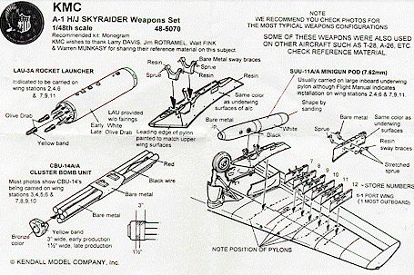
the likely candidates from the kit and KMC’s A-1H/J Skyraider Weapons Set 48-5070
(thinking, hoping that the finished parts would inspire some decisions !).
Even though
I’m still tossing up my Skyraider’s ordnance configuration I decided to assemble
the likely candidates from the kit and KMC’s A-1H/J Skyraider Weapons Set 48-5070
(thinking, hoping that the finished parts would inspire some decisions !).
Having already spent some time cutting out and cleaning up the kit’s HVAR parts (refer to "Part One"), a quick check in broad daylight showed most required a little more attention - much to my disgust !.
So it was out with the Xacto knife again and medium grade sandpaper . Once satisfied with "Operation Clean-up Part 2" (by this stage I was thinking "is this really worth the effort ?") the rockets were assembled by simply gluing the 12 front sections to their rear sections. Tamiya’s thoughtful engineering is evident as a keyed plug firmly secures the single join on each rocket where the rocket head and fins meet.
Once the glue was set, the rockets were wiped clean with a moist rag, to remove all sanding dust, and then painted according to kit instructions.
After all this time and effort on the HVARs I was starting to wonder "can I really be bothered with any other ordnance options ?". Well AMS ("Advanced Modelling Syndrome/Sickness") again took over and I went on to assemble, paint and weather twelve mini-guns (six each from the kit and KMC set). These will not go to waste as I intend to do a USAF "Sandy", finished in typical SEA camo scheme, in the near future as a companion to the USN marked model (probably when Tamiya gets around to releasing the USAF version).
F u e l T a n k s |
Three external fuel tanks are provided in the kit, each consists of an upper and lower half.
The two underwing drop tanks each have small stabilising fins molded into their rear lower half. The 300 gallon centreline fuel tank is easily identified by the lack of stabilising fins. All three tanks are to have poly caps inserted into their locating plugs to allow quick removal from its pylon. The underwing tanks are designed to be interchangeable with 2000lb bombs.
Two poly caps were placed in their locating recesses in each upper tank part. I found the plugs for the poly cap recesses needed to be sanded down slightly to allow the seams to fully close (very ominous signs of things to come !). Super-glue, "Zap-a-Gap" gel, was carefully placed on the matting surfaces with a tooth pick, the parts were then held tight for a couple of minutes for the glue to fully set (making damn sure my fingers were placed away from the seams so as to NOT super glue my fingertips to the seams !).
There are several advantages of using super-glue on long curved seams, such as fuel tanks. Firstly, the seam will be glued and filled all within a minute or two. Secondly, super-glue is less likely to "shrink" as I’ve found some tube-like glues do. Any excess glue squeezed out of the seam can be easily sanded smooth. I’m fast coming round to the "school of thought" that supports using super-glue for all my major construction. Well that’s the theory, now for reality !
As the fuel tanks were meant to be "seamless", the seams on my fuel tanks looked "less than perfect". A spray of white confirmed my worst fears as the seams stuck out "like sore thumbs". So super-glue, my preferred gap filler, was used to "touch up" all seams., these were then rigorously smoothed down with a sanding block and wet’n’dry sandpaper. Any lost panel line detail was restored with the new Xacto blade.
A couple more light coats of white were applied, some areas were still a little rough - these were then lightly sanded. Now that the seams were "perfect", each fuel tank was mounted on two wooden skewers and received a few more light coats of white.
If the construction and painting of the three fuel tanks sounds like a bit of saga then your damn right. Being "seamless", the horizontal seams needed to be totally eliminated so as to not stand out under the white paint - give me "seamed" fuel tanks, like you find on P-51s, any day !
C o c k p i t |
The kit cockpit is made up of only five pieces; cockpit tub/side consoles (all-in-one), floor, rear wall, front instrument panel/foot pedals and joystick. All parts were base coated Dark Gull Grey FS36231 (as advised by members of the rec.scale.models newsgroup). The instrument panel, side consoles and joystick handle were painted Matt Black and drybrushed with light grey and then aluminium to "lift" the detail.
Tamiya’s seat has minimal detail so it was promptly replaced with the USN type seat from KMC’s A-1H/J Skyraider Update Set 48-4015 (designed for the Monogram kit). The KMC set also has the USAF "Yankee" seat.
KMC’s resin USN seat is very well detailed as it incorporates seat/lap belts and frame detail (unlike the kit seat which is very basic). Following the KMC instructions, the seat was first sprayed Dark Gull Grey FS36231, the lap belts and buckles were then handpainted. A light dry-brushing highlighted the edges and raised detail. The finished seat was then firmly attached to the cockpit tub floor with super glue.
The joystick was cemented in place on the cockpit floor followed by the rear wall and front instrument panel parts.
F u s e l a g e |
Having taken care of the cockpit it was onto the rest of the fuselage. The front inside of each fuselage half was sprayed Dark Gull Grey. The completed cockpit tub was glued into the right fuselage side before cementing the fuselage halves together (the one-piece tail wheel well had been glued in placed in the initial construction completed in "Part One").
The fit of the fuselage is very good, however I suggest dry fitting the parts several times to find out the best way to put the two halves together. This recommendation may sound odd for a Tamiya kit but with my first couple of dry fit attempts I mismatched the rear fuselage seams (no I was not drunk at the time !).
I found the best way to put the fuselage together is to carefully match up the nose section, ensure both top and bottom seams are perfectly aligned, and then progressively press the remainder of the fuselage together (ie. work back down the fuselage to the tail). This is not a flaw of the kit just an area to take some care.
The lower fuselage plug (part #B2 - radiator grille ?) and several small fairings (two on each side) were cemented in place to complete the fuselage. All fuselage seams were sanded smooth after a few days.
W i n g s |
The inner wheel well walls, with undercarriage doors, had been glued in place and painted White earlier. Tube glue was placed on all matting surfaces on the lower wing before the upper wing sections were firmly placed ontop.
The fit of the left wing was very good. On the right wing there was an annoying small gap, about 5mm in length, either side of where the inner cannon barrel is to be placed. A small amount of Kibri liquid glue was applied around the gap to slightly melt the plastic to close the gap. This almost worked - once again super-glue was used to fully close the gap. After a few days all seams were gently sanded with a medium and fine grade wet’n’dry sandpaper.
The fuselage and wings were then brought together - the fit was near perfect. Only a tiny bit of filler was need at the forward and rear fuselage-to-wing joins, and front left fuselage to wing join. Any gaps were more likely my fault rather than the kit’s.
K i t R u n n i n g T i m e |
Part 1 6hrs
Part 2 7hrs
S o F a r , S o G o o d ! |
Well that concludes "Part Two". I’ve been pleasantly surprised by how far I’ve got with the Skyraider in such a short amount of time - total "running" build time to date is 13 hours (OK so I’m a slow builder as I like to take my time).
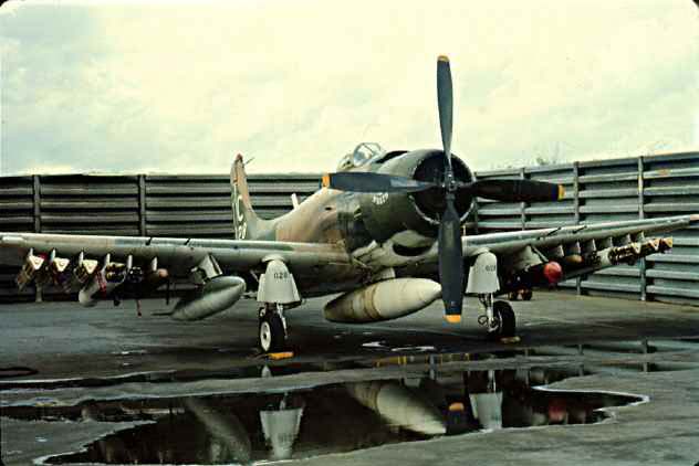
The large size of the aircraft is evident when the completed model airframe is compared to smaller WW2 aircraft, eg. Bf109, Fw190, Wildcat, Spitfire and P-51. In short, the Skyraider was a beast of an aircraft !
If you’ve read the story so far you’ll know that the kit is reasonably easy to build. The only real problem/s I found so far are the three fuel tanks with their less than "seamless" seams.
As for the markings to be applied, I’ve decided on the box-art scheme from VA-176 "Thunderbolts" MiG killer AK409 (as per Tamiya kit decals and Third Group set) or AK405 (as per AMD set). I would be interested if anyone can provide a definitive photo of a/c no. 37543 to clear up the AK405 versus AK409 issue.
By the time I get around to writing "Part Three" I hope to have completed painting, decaling and weathering the airframe, followed by the "add-on" parts (flaps, dive brakes, undercarriage, ordnance, canopy etc.). Well that’s the current "Game Plan".
Many thanks to Brown Ryle and Richard Chafer for their assistance with a few questions I had about USN Skyraiders.
Happy modelling to all !
JOHN KERR
of the South Australian Plastic Modeller’s Association (SAPMA),
Adelaide, S.A.
Back to HyperScale Main Page
Back to Features Page