Home
| What's New |
Features |
Gallery |
Reviews |
Reference |
Forum |
Search
Home
| What's New |
Features |
Gallery |
Reviews |
Reference |
Forum |
Search
|
|
|
Supermarine Spitfire IX
by Robert Swaddling
I started building the ICM 1/48 scale Spitfire IX on 25 October, 2000. The first step was to airbrush all the interior green after cleaning up the parts. I also test fitted the fuselage halves together and held them with tape. I did the same with the wings and then the wing to fuselage. The dihedral looked correct in my opinion. No warpage or anything unusual was encountered. There was nothing more serious than mold parting lines and moderate flash to clean up. The styrene is of medium softness and is easy to work with. I cut the windscreen and the closed canopy parts from the sprue (they attach on the edges where you can easily clean the sprue mark and leave no visible trace) and set them in place for an initial look. The shape looks perfect and the parts are clearer than my first impression when doing the initial review. The distortion that I saw in the “blown” hood is understandable because the hood is bulged just as on the real Spitfire. I test fitted one horizontal stabilizer and it “snicked” into place at the proper right-angle to the vertical fin. I took this as a very good sign. When I held the rudder in place the whole empennage looked terrific.
I built the Spitfire almost straight from the box. I added some essentials however. These included:
These were basic but necessary at least for me. I removed the headrest from the armour plate and installed it on the fuselage frame. The mounting pin helps fill the hole which I puttied up.
Since I intend to finish my Mk. IX with all the cowls in place I assembled the Merlin without paint. I gave it a coat of dark gray and painted the exhaust stacks after the camouflage was done. Care must be taken with assembly here to ensure good alignment since the propeller shaft is mounted on the front of the reduction gear box as on the real aircraft, and the exhaust stacks are mounted to the engine cylinder blocks. After cleaning up the parts the fit was very good. It is obvious what has been sacrificed to fit the completed engine assembly under the cowls. Since the 1/48 scale plastic cowls are overly thick, there is no room for a full-sized 1/48 scale engine. Much is missing including the prominent intercooler of the 60 series Merlin making it look like a Merlin 45 or other “short” Merlin. The aftermarket guys will have a ball doing up a scale Merlin 66 with all the plumbing and wiring etc. to enable us to do a Spitfire IX without cowls at all as in an engine change diorama. I found that, with the Merlin assembled and using all the parts as called out on the instructions, I had to remove the valve covers to get the upper cowl to fit over the engine. This is not a problem for me since I am building the aircraft with all the cowls in place. This is just a "heads up" for anyone wanting to do their Mk. IX with the cowls in place but removable. The built up samples that I saw in Chicago were done this way so it is not impossible to do but would be a bit involved and I am building this kit as straight out of the box as possible. On my next kit I will assemble only the essential engine parts needed to get the propeller shaft out where it is required (engine block and reduction gear) and leave the exhaust stacks off as I discovered that they can be installed anytime after the assembly and painting.
This model is a perfect candidate to install a Cooper Details or other aftermarket cockpit set of your choice. The kit parts are fine, but a truly outstanding model could result from a little extra effort. I painted the instrument panel. It is passable but certainly not the best Spitfire instrument panel that I have seen. The decal included for use instead of painting is very basic and I would not recommend it at all. I completed the cockpit painting and assembly and taped the fuselage together for a trial fit. An oversight on my part in my initial review was that I stated that the gunsight is the gyroscopic type (probably a case of wishful thinking and weak bifocals). On closer inspection of the clear part (wearing my Optivisor, mandatory for the over 50 crowd) I saw that it is the regular Mk.. V gunsight. The cockpit interior actually inserts up through the bottom after the fuselage is together. I also installed the firewall/engine assembly and the taped together wings. Everything came together pretty good except that I had to file the bottom of the firewall so that the bottom of the wing would come all the way up to the fuselage properly. I then found that the firewall was holding the fuselage halves out too far (which made the upper cowl too narrow) and was also too high for proper fit of the upper cowl. Consequently, when all was done, I had filed the firewall all the way around. I also took some off the engine bearers so that the lower cowl would come up all the way to the side cowl. With wings and cowls taped in place, I test fitted the spinner and the overall appearance of the nose area is right on the money. This indicated a problem with the fit at the leading edge wing roots where the upper halves don't extend quite far enough forward to mate up with the lower wing leading edge.
The fuselage was flat sanded for true fit (no locating pins) and glued together. After the fuselage was dry I fitted the firewall in and glued it in place. I thinned the forward former ( part B 25 ) by about half and filed the diameter of it down so that all four cowls would come together around it and be in contact with each other. The side cowls were then glued to part B 25.
The upper cowl was glued on next and it fit almost perfectly. I had to file and sand the back edge down so that it smoothly transitioned down to the fuel tank as on the real aircraft where it covers the Intercooler hence the balloon cowling.
Moving to the wing, I cut the elevators off the horizontal stabilizers for repositioning in the "full down" position. The molded panel lines are very shallow so be very careful with the first pass with the old X-acto No 11. I actually cut using the back side of the knife point which removes a sliver of plastic rather than cutting. I opened up the shell ejector chute holes corresponding to the "c" wing armament ( two .303's and one inboard 20mm cannon ). I also filed and fitted both cannon bay covers and glued them in place as I want the aircraft to appear ready to start and opening the cannon bay would take a lot more detail parts than what is given. ICM is a bit confused here for they give you drum magazines for the cannon if you are going to use the early large blister instead of the later single cannon blister. For the single cannon blister you are given the proper belt feed mechanism used in the "c" wing. The drum magazine was only used on the "b" wing and would be totally wrong on any Spitfire Mk. IX. Besides that the blister for a "b" wing is totally different than either blister supplied with this kit and would require another blister on the wing underside. I think that they sort of took a guess as to why the "c" wing had two styles of cannon blisters ( large and small ), and guessed wrong. For anyone interested, the small cannon blister is 6 scale inches too short and a good inch too low. I cleaned up the wing halves and trial fit the wingtips in place. At first I thought that they were not thick enough but on close inspection discovered that the mounting tabs are too thick and spread the wing apart making the wingtip appear too thin. I simply cut off the mounting tab and they are perfect. I test fit the wing assembly to the fuselage assembly and started adjusting the fit problem mentioned earlier. I filed off the bottoms of the cockpit cross members which helped a bit and then started filing the rear of the wing assembly where it joins the fuselage. This allows the wing to move back in the fuselage till the two leading edges line up. Of course the lower trailing edge starts coming back out from under the upper fairings of the fuselage but this is easily cleaned up and will be fine. With the wing assembly held in place I trial fit the lower cowl and it was really good.
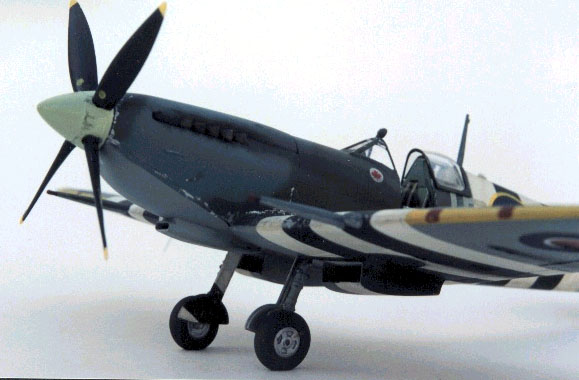
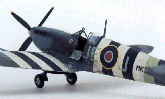
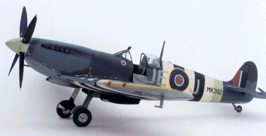
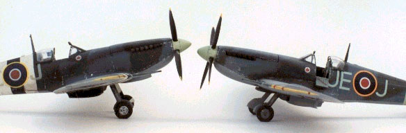
I decided to finish my Spitfire as MK392 JE-J as the box art aircraft. Since this Spitfire is shown with the D-Day stripes I first masked the cockpit, the radiators and the air intake; then airbrushed all the white areas for the stripes and also sprayed the filled areas at the same time to check for mistakes. Then I started all the measuring and masking for the white areas of the D-Day stripes. This was tedious work. The stripes on the fuselage are the mandated 18 inch width. On the wing, to start at the aileron and work in to the wing root, the stripes need to be 16 inches wide. If you go 18 inch wide stripes on the wing, they will go from the root out to the roundel and of course some were seen like that and even over part of the roundel. There are many variations on the D-Day stripes. My friend, 401 Sqn. Spitfire pilot, Jerry Billing says that on his aircraft they were painted on very crudely freehand and that higher ranking officers’ aircraft had them masked and sprayed on very neatly. He also says that the stripes on the gear doors didn’t always line up with the stripes on the wings properly as they were painted on while in the down position and sort of guessed at.
The aircraft was painted with Testor’s Model Master paints. I left the horizontal stabilizers off till the painting was completed to simplify masking. I masked the white invasion stripes and then sprayed the area for the fuselage band and the spinner and backplate Sky. I masked the fuselage band off and sprayed the black stripes. I masked these off, then cut the masking tape from over the wheel wells, and sprayed the entire undersurfaces including the horizontal stabs/elevators, wheel wells, oleo legs, inner gear doors, tailwheel, and pitot head, Medium Sea Grey. Again, I masked the upper - lower colour demarcation line (simply flipped the horizontal stabs over on inside out masking tape) and sprayed all the upper surfaces Ocean Grey. Spitfires were sprayed using rubber mats as camouflage masks. I made up a set of masks using “Playtex” rubber glove material, backed with masking tape for stiffening, cut to the Spitfire pattern. I have used and reused these masks on all my Spitfires, Mk. I – Mk. 22 and they are great and save a lot of time. I use “Blue Tac “ to stick the masks to the aircraft which holds them off the surface a bit so that the colour demarcation is a very fine soft edge. The masks were attached to the Ocean Grey surface and Dark Green was then sprayed. I was careful to spray as straight on to the masks as possible so that I wouldn’t get paint bleed underneath. I removed all the masking and the “look” of that Mk. IX in her war paint is an eye popper! Next I masked the leading edges for the yellow and sprayed these and the propeller blades. I had filed and sanded substantial flash from these items earlier. I was certainly not disappointed with this model at all after seeing it painted up. The distinctive shape came together with the camouflage.
I glued the horizontal stabs on and then added the elevators in the full “down” position. Paint repairs were made and I clear glossed the entire aircraft with Testors Acrylic . Now came the decals. I had tried a test decal (the instrument panel) on one of the unused side cowls and it was OK. Being a kit evaluation , I used the kit decals and actually liked them. I had no problems using Micro-set as an undercoat and Micro-sol as a topping. They seem a bit stiff but settled down into the panel lines. There was no problem of tearing. The hardest test of any decal is to apply a light colour over invasion stripes. I didn’t paint any white circle to be a solid colour under the roundel as I usually do with my own aircraft as this one is sort of a test. Results? Not bad. You can see the dark of the black stripe but it is glaringly obvious. I also added the brace that runs beneath the small perspex behind the canopy using some scrap plastic. I drilled out the “up-lock” rings on the oleo legs and cleaned up the mold lines. The oleo scissor links are the best that I have ever used. I cleaned up the Ocidental tyres and painted them with the best tyre colour that I have ever used, Floquil Grimy Black. The Ocidental four spoke wheel inserts are used but need to be shimmed out as they sit too deep in the tyre. The Ocidental covered wheel inserts are perfect for this. Approximately 1/16” must be cut off of the ICM axles tp permit the Ocidental wheels to fit. I painted and added the tailwheel. I added the undercarriage doors to the oleo legs and these are great. As Roy Sutherland says , they should be curved out a bit to allow the undercarriage to not retract all the way into the wing but this is not too noticable. I will glue the oleo legs in their mounting holes later but I have test fitted them and they are fine. I’ll also glue the wheels to the oleo legs after they are in place. I cleaned up and added the cannon and the hemispherical cover over the unused cannon tube (standard “c” wing). No problems here and they look perfect.
I measured the 4” yellow tips to the propeller blades and painted the main sections black. Before gluing the blades to the spinner back plate, cut approx. 1/16” off the ends that go inside the spinner or they won’t clear the propeller shaft. The spinner was glued on the back plate as the assembly is tight enough on the propeller shaft to hold the propeller on and will allow you to remove it later for transport. With the markings and propeller in place she really looks great and you can’t help but to hold her up, close one eye, and do a couple wing-overs when nobody is looking. I have been calling this kit just the way that I have seen it and have been reading some horror stories on ICM’s quality control. I hope that they address these problems as they should if they want to break into the huge Western Market with models that appeal to everyone in type chosen and in quality (aircraft, Armour, Figures, and Ships) You should see the 1:48 scale figures coming out to go with the Spitfire. Start a diorama base now. These guys look real! I flat coated the entire aircraft with Testors Acrylic. All the small details were now added to the Spitfire IX and with each one there was no problem. I left the cockpit door off till the last. I have yet to glue the oleo legs in place as they are a very precision fit that holds the gear from flopping around, out of position, and if I ever am asked by ICM to ship their completed model to them, I’ll be able to remove the propeller and undercarriage. I painted the reflector gun sight and installed it. The windscreen and canopy frames were hand painted using Testors Model Master Acrylic (easier to correct slop-overs using a toothpick) and the insides were done with acrylic semi gloss black. The small perspex panel behind the sliding canopy is a bit too long and was filed to the proper length. I also filed the cutout in the back of the canopy frame for the aerial mast to fit into when the canopy is slid all the way back. I glued all the clear parts in place with Elmer’s white glue. The hemispherical mirror (very realistic) was installed and then painted. Weathering comprised paint chipping, oil streaking, cordite burns and finally the exhaust stain. I drilled a # 80 hole forward of the starboard aileron for the I.F.F. rod antenna which was installed using a small filament wire out of a 100 Watt light bulb. Finally I installed the cockpit door and the ICM Spitfire was completed.
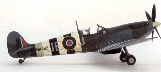
I am very pleased with ICM Spitfire IX. It looks and sits right to me. As the kit was given to me for evaluation by ICM I tried to build it as straight from the box as possible. I did make some minor modifications and more are probably needed for advanced Spitfire modellers to be satisfied. But it really looks fine the way it is.
Viewing the completed model is a reward after all the sink mark filling, flash removing, part fitting and time consuming construction on this kit. But isn’t that what this hobby is all about? A pastime that gives a sense of accomplishment after completion (using patience and skill) that is tangible for yourself or others to admire. Not like watching TV. I suggest giving this kit a try. Don’t be spoiled by the “shake the box” kits. This is way more fun. ICM's Spitfire IX represents, for me, interesting and entertaining model building. I do appreciate a Tamiya or Hasegawa “perfect fit the first time type kit” but solving these fit problems is a bit of a challenge and when it came together I felt like I had accomplished something beyond simple assembly. This kit is not for beginners but someone with average skills (like myself) will be pleased with the results. Model and Text Copyright © 2000 by Robert
Swaddling
|