Home
| What's New |
Features |
Gallery |
Reviews |
Reference |
Forum |
Search
Home
| What's New |
Features |
Gallery |
Reviews |
Reference |
Forum |
Search
|
|
|
Supermarine Spitfire PR.XIX by Jim Kiker
Dedicated to Mr. Ed Powles, with respect and appreciation.
Having been in the reconnaissance business myself, I have a special fondness for “recce” aircraft. Some time after Academy released their 1/48 scale Mk XIV Spitfires, I ran across an excellent walk around of the Swedish S-31 (PR XIX) in the IPMS Stockholm web site archives, and I was off! Then, one of my local model geek buds found out I was thinking about doing the PR XIX, and he “steered” me to one of the aircraft used by (then) Flt. Lt. Ed Powles. During construction, Wally also arranged for me to have a conversation with Mr. Powles; what a kick in the pants to speak with the man who flew the exact airplane you’re building. Flt. Lt. Ed Powles led a two-plane detachment from 81 (PR) Squadron, based in Hong Kong in the early 1950’s. His exploits included some early cold-war aerial reconnaissance, as well as taking some of the first meteorological measurements at altitude in that region of the world. And then there was the time he took his PR XIX up to 51,000 ft. Noting a problem with the cabin pressurization, he put the nose down- and darn near went supersonic during the ensuing plunge back toward the sea. He later calculated that he got up to at least .96 Mach before regaining use of his flight controls in the denser lower air (having encountered locked controls due to compressibility near Mach 1), and leveled out approximately 1,500 ft above the sea. To top it off, Mr. Powles is over 6 feet tall and barely fit into the Spitfire with the seat fully lowered. What a great story!
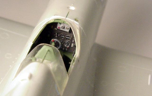
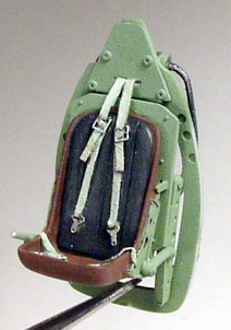
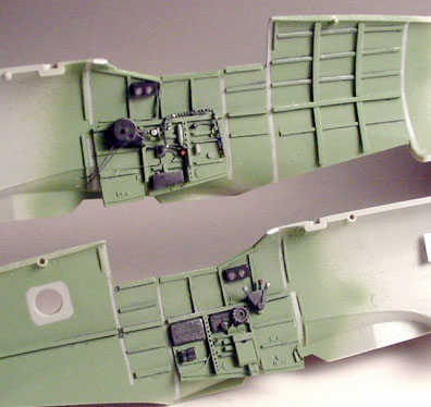
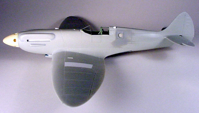
Academy produced two Mk XIV Spitfire kits, including both the ”c” winged version and the later bubble-canopied one with the “e” wing, in 1/48 scale. The Mk XIVc kit became the basis for this project. These kits build up pretty well and feature fine panel line engraving. While the wings are especially nice in shape, I’ve come to the conclusion, along with some Spitfire experts, that the fuselage is a bit deep. This would be a very difficult thing to fix IMO, and I limited myself to sanding down the forward nose area somewhat on the top and bottom during construction. The interior detail is rather Spartan for my taste, and the spinner and prop require some real work. Parts fit is not bad, but this isn’t a “shake ‘n bake” kit. KMC produced a nice resin upgrade set for this kit, and while it’s currently discontinued, it can be found. It provides a complete cockpit, new spinner and props (which is also available as a separate set, I believe), a new upper engine cowling, and new radiators, much of which I made use of to great effect.
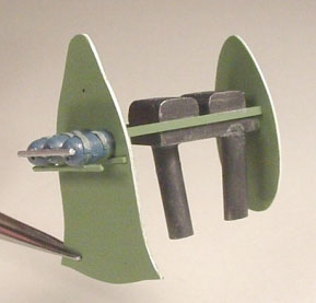
Converting the Mk XIV into a PR XIX proved to be deceptively non-trivial! Fuselage1. Using references, mark and scribe camera access panels onto each fuselage side. The left one also gets a camera port drilled out. 2. Glue the standard pilot’s entry hatch into place and erase the seams. The first couple of dozen (give or take) aircraft were built as unpressurized a/c, and featured the standard Spitfire pilot entry hatch on the left side of the cockpit. Eliminating the access door only applies to pressurized aircraft, like the one I modeled. 3. Fabricate a new cabin pressurization scoop, to go below the left engine exhaust pipes. Again, if you build a PR XIX from during WWII, check your references to see if you need to add this scoop or not. 4. The rear, fixed portion of the canopy on the Academy kit is too short from front to back and must be replaced. In addition, this piece extended down about 2” lower than normal Spits. I cut the rear area down even with the sliding section canopy sills, made a master, and vacuformed a new rear section. I glued this piece in place, smoothed the joins, and simply painted the horizontal frames in their correct location during painting. 5. Add a solid pressure bulkhead at the rear of the cockpit if you’re doing a pressurized bird.
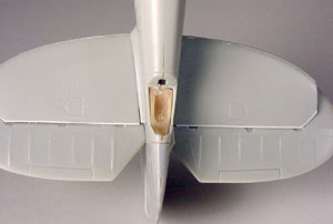
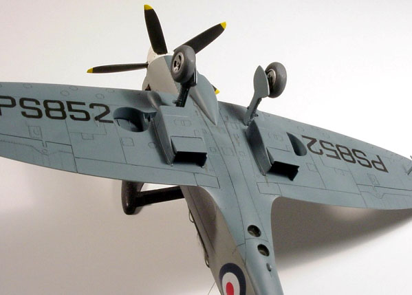
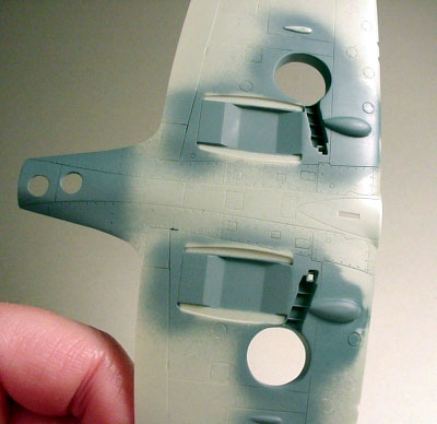
7. I also needed to replace the kit’s windscreen with a one-piece wrap-around unit. One of the Falcon conversion sets has one, and Aeroclub makes a set of four Spit canopies for different marks, including a PR. When I test-fit this piece, the leading edge sits back farther than the standard kit piece, and the round shape of the bottom of the piece doesn’t fit the kit. I added some sheet plastic to the front of the cockpit and shaped it to fit the new windscreen. Wings1. Using references, mark and drill out the two lower camera ports; note that they are offset slightly from the a/c centerline. Mine are 3/16” diameter. 2. The Mk XIV wings feature (correctly) the short- span ailerons used on the type; unfortunately, the PR XIX had the normal, longer-span ailerons, so fill the outer ends of the kit’s ailerons and extend the hinge line out to where the wingtip joins. 3. The PR XIX was unarmed, so of course the cannons and their upper wing bulges had to go. And so do all of the gun access panels, panel lines, shell chutes, the whole lot. I filled in all the gun panel lines with superglue, using a pin as an applicator, a short section at a time, then hit it with accelerator. Remember to sand each line down as soon as you’re finished getting the superglue dry, before it hardens completely. Rescribe the remaining panel lines as needed. This proved to be the most tedious part of the project! Here’s a shot of the airframe much later during construction. Looking down the wing, you can see the rescribed ailerons and the absence of gun access panels. Also note the dropped elevators and the scratchbuilt scoops, on the engine (the original having been lost!) and the pressurization exhaust just behind the cockpit. Finally, although it’s all but invisible here, you can see the fixed rear portion of the canopy and how my vacuformed piece comes down even with the sliding section rails.
4. Next, make the two fuel boost pump fairings that go under the wings, in front of the wheel wells. The XIX had the entire front of the wings forward of the main spar made into fuel tanks, with a boost pump for each. I started with half-round strip plastic stock and carved/sanded these pieces; the hard part is getting them to match! 5. There are also two small, thin fairings at about mid-span on the lower wings. I robbed them from a spare Otaki (Arii) Mk VIII kit; otherwise, they’re another scratchbuilt item.
General Detailing
4. The wheel wells needed some accurizing as well. I cut out the molded-in wheel wells and rounded out the opening somewhat (they seem a little oddly shaped to my eyes). I then lined them with .005” plastic sheet, installed to go all the way in to meet the bottom side of the upper wings. I also added the two stiffening ribs; note that part of the inner rib actually protrudes from the top if the upper wing. 5. General airframe additions included some added detail in the
carburetor scoop opening and in the well for the tail wheel. Looking at my references, the carburetor
opening had a half-moon-shaped plate in it.
I added this from sheet plastic, and also added a backing plate and some
micro screen in the opening, and painted all this before adding this front
section to the scoop.
6. I separated the elevators from the horizontal tail pieces, refinished the edges, and re-installed them at about a 25 degree down angle; and yes, I did move the stick forward to match! 7. I used the radiators from the KMC set, since they are about .030” wider than the kit parts. They still fit the kit’s mounts, only the actual openings are wider and more to scale. I opened up the cooling flaps at the rear ends, made new flaps and actuators, and added more micro screen to the back of the resin pieces. I painted the insides of the radiators before installing them. 8. During construction, I used Mr. Surfacer 500 to blend the joint lines of the engine cylinder head covers, the carburetor intake scoop, and the pressurization scoop. I used thin CA on the joint between the wings and fuselage, smoothing it all out and re-scribing panel lines as needed. 9. If you want to do a PR conversion like this, check your references closely for the correct type of wheels. Flying well after WWII, my a/c had three-spoke wheels. The kit comes with four-spoke units, which in my case had to be replaced.
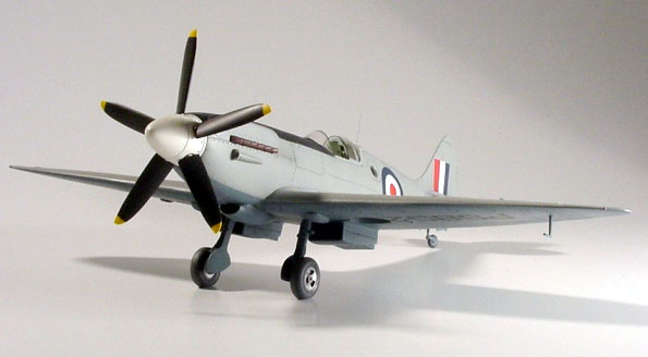
There are several pictures of PS 852, Powles’ favorite, and her sister ship PS 854 taken from their sojourn in Hong Kong. These two airplanes went through several paint scheme changes during this period. I depicted the aircraft as she was painted in early 1952, when Mr. Powles had his brush with the Grim Reaper near the Mach. The basic scheme is Medium Sea Grey (MSG) on all upper surfaces with PRU Blue on the bottom. The RAF type “D” roundels appeared on the fuselage and upper wings only. A/c serial numbers were carried on the fuselage, and repeated on the bottom of the wings in black.
Note that the underwing serials are smaller than those seen on other late-Mark Spitfires. A black anti-glare panel was added down the nose in front of the cockpit, just covering the top edge of the Griffon engine’s cylinder head covers. Per Mr. Powles’ description, the aircraft wore a white spinner.
The cockpit canopy framing was masked and painted British Interior Green, then completed in MSG; note that the windscreen frames and the front frame of the sliding section are painted black. The model was painted with Floquil and Model Master paints, thinned with Dio Sol. I added two thin coats of clear Future before decaling and another coat over the decals. The roundels and fin flash came from one of Aeromaster’s late mark Spitfire sheets, the serials from one of Extra Decals’ RAF serial number sheets, and the underwing serials from Daco Products’ Belgian Spitfire codes and numbers sheet.
I put a thin oil wash into the panel lines, fairly dark (Payne’s Gray) in the engine panels, control surfaces, other removable panels, and in the panel lines on the bottom of the a/c; and a slightly lighter shade in the top side lines. The effect is fairly subtle, which I believe is more accurate for this aircraft. A bit of exhaust streaking and a bit of silver paint chipping and wear on the wings (which doesn’t show much in the photos) were also added. .005” steel wire was added for the whip antenna and the short aerial on the tail warning fairing below the fuselage to complete construction. The final touch was a semi-flat coat of clear acrylic paint.
1. “Supermarine Spitfire PR Mk. XIX,” by Theiner and Patek, published by MPM. 2. “Wings of Fame” quarterly, vol. 5, published by Aerospace Publishing, Ltd. The specific article is “Spitfire Spyplanes” by Dr. Alfred Price. 3. “Aeroplane” magazine, from November and December 1998, articles written by Flt. Lt. Edward Powles. 4. Interview with Mr. Powles to confirm markings. 5. Supermarine Spitfire S-31 Walk Around, by Joachim Smith, IPMS Stockholm Newsletter, August 1998. 6. “Spitfire- In Action”, published by Squadron/Signal Publications.
1. To Wally, for steering me onto this particular aircraft, and for introducing me to Mr. Ed Powles. 2. To everyone at Accurate Miniatures for making the terrific photographs possible. 3. To Roy Sutherland, Bruce Archer, Charles Metz, Paul Fontenoy, and others for their assistance during this project.
As of January, 2001, I have seen a PR XIX conversion set advertised as a future release by Airwaves, on the Victory Models web site. If so, it would make the project much easier! Model, Text and Images Copyright © 2000 by Jim
Kiker
| |||||||||||||||||||||||||
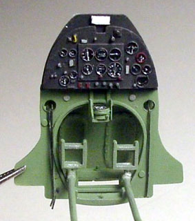 I like to add a certain level of detail to
my models, including the cockpit, wheel wells, and airframe.
I like to add a certain level of detail to
my models, including the cockpit, wheel wells, and airframe.