Home
| What's New |
Features |
Gallery |
Reviews |
Reference |
Forum |
Search
Home
| What's New |
Features |
Gallery |
Reviews |
Reference |
Forum |
Search
|
|
Focke-Wulf Ta 152H-1 by Glenn Irvine
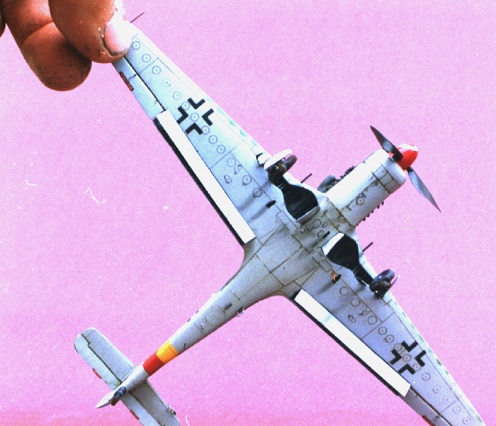
Glenn Irvine builds and details Frog's old, old Ta 152H. There are six images of this remarkable project in the text and nine more thumbnailed images at the bottom of the page.
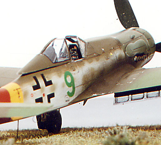
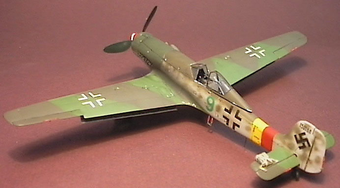
The Ta 152 was the final development of the Focke-Wulf 190 fighter series. Developed to improve the medium to high altitude performance of the fighter serries at that time, as the low to medium altitude was served well by the 190 A&D series and the 109 G&K. The fighter was produced in very limited numbers and reached action in 1945 with JG 301, the only documented unit to receive them. When I built this kit in the mid to late 80's, there were no other kits of the Ta 152 available and getting hold of the Frog example was quite difficult. So I decided to rebuild an old kit I had built in the late 70's. This was a challenge! As I had only recently rediscovered the hobby after about 10 years I had no resources much in the way of references except the two Kookaburra booklets on the 190 series, so a search for information yielded little useful except for an article by Dave Richardson in an old copy of the APMA magazine with a profile on Green 9, until the release of Heinz Nowarra's book on the 190 & 152 which helped a lot. A copy of 'Wings of the Luftwaffe', and the bonanza Great Book of WWII airplanes were both helpful too. I came by a copy of some reasonably accurate plans from an old issue of Aviation News by Keith Woodcock and between all this and available photos I was able to make a start.
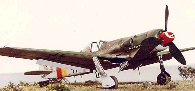
Much later in the build, when I was tearing my hair out over how to detail the wheel wells with no information, I received the Holy Grail - The Trimaster Ta 152. This allowed me to finish the model reasonably accurately, with the exception of one mistake made prior to obtaining the accurate information . The radiator cowl, though now accurate externally, has a radiator patterned after the D9. I did not realise that Frog had actually got this bit right and had already "corrected" this detail! One small glitch!!!..........
The kit itself is very basic, typical of most Frog kits, requiring very little assembly. Since I started with a built kit there was a little extra to rebuilding it. I prepared the model by spraying with oven cleaner to remove the old paint. An old toothbrush and plenty of fresh water helped with this messy task. Remember, be careful with oven cleaner as it is caustic and can cause burns to sensitive skin or dermatitis. Use rubber gloves. When the paint was removed, I split the model apart along the assembly lines after soaking it in bleach to soften old glue joints. I filed down all flat-joining surfaces. It was not necessary to separate the fuselage halves as the joints were okay. I sanded off all surface detail in preparation for later rescribing. The kit panel lines were inaccurate anyway. Using a razor saw I removed the rear canopy fairing from the fuselage. I discarded the canopy as it was destined to be replaced with a Falcon vacform. While I was at it, I tossed the rear tailplane, the spinner, the wheels and oleos into the spares box. I used the oleo leg/covers as patterns for new ones made from card. The inner covers are quite good but need modifying, so I kept these.
Borrowed Components To complete this model I needed some spares from other kits. The tailplane from the old Hasegawa D9, tailwheel from the Airfix D9 (this is still the most accurately sized tailwheel for the later 190 series in 1/72) also the propeller (as the Frog one no longer existed). Added to this list was a Falcon/Squadron blown type 190 vacform canopy, Italeri D9 spinner, hypodermic tubing, Model Technologies seatbelt buckles and rudder pedal, shim brass and tubing selection from K&S, Slaters microstrip & plasticard. 2 'o' rings, fuse wire, lead wire etc. You get the idea!
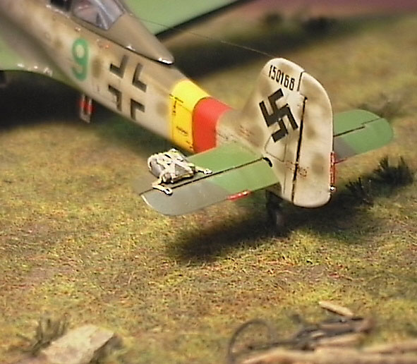
Major Modifications Comparing the fuselage to an accurate plan, the vertical tail is too short and too narrow and the wrong shape, I built up the area using plasticard and superglue, then scratchbuilt a new rudder. The upper fuselage decking in front of the windscreen is incorrect and needed the subtle bulges built up with filler to achieve a flatter cross-section. The fuselage at the cockpit sidewall area is too narrow and needed building up with filler. The under nose cowling area is too square at the wing root and needed blending in to the round nose area directly behind the radiator cowl. I drilled a small hole (No 75 drill bit) at front and rear of the exhaust manifolds and sanded off the exhaust stubs, opening up a rectangular hole to accommodate the new exhaust. The wing root at the rear undersurface is very wrong and needed some extensive sanding and filling to reduce the bulge that extends into the lower wing section. Sanding the upper rear wing root was also required as the wing root is too high up the fuselage resulting in the step seen on the undersurface. Subtle work on both surfaces was required to repair this. I was thankful for the thick components of old kits - I needed the extra plastic!
The wings had the flaps removed. The easiest method for this is a motor tool and a lot of filing. The wing tips are too square and were altered. I thinned down the wheel well and flap area until it was paper-thin. I also removed all control surfaces. The radiator cowl was reshaped. I modelled mine in the closed position as I think it enhances the look of the aircraft. This simplified construction as you would need to do a lot more work to model them open, cowl flaps, actuator rods, the front of the engine cowling under the flaps and internal detail etc. Propeller blades needed altering to match the shape of the VS11 prop. The fuselage cockpit area needed major thinning down from the inside till paper-thin and removal of the instrument shroud. At this point I compared the vacform canopy to the fuselage and modified the fuselage to match the canopy contour.
I scratchbuilt a new instrument panel from sheet styrene. Remember, these were the days before detail sets! For those who are vaguely interested, this is how I detailed my 152 cockpit:
The canopy was detailed after separating into two by adding very thin microstrip to the inner frames with white glue. The headrest was scratchbuilt from plastic and brass shim for the armour plate, this was painted along with the inner frames and washed and dry brushed. The parts were then assembled.
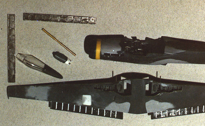
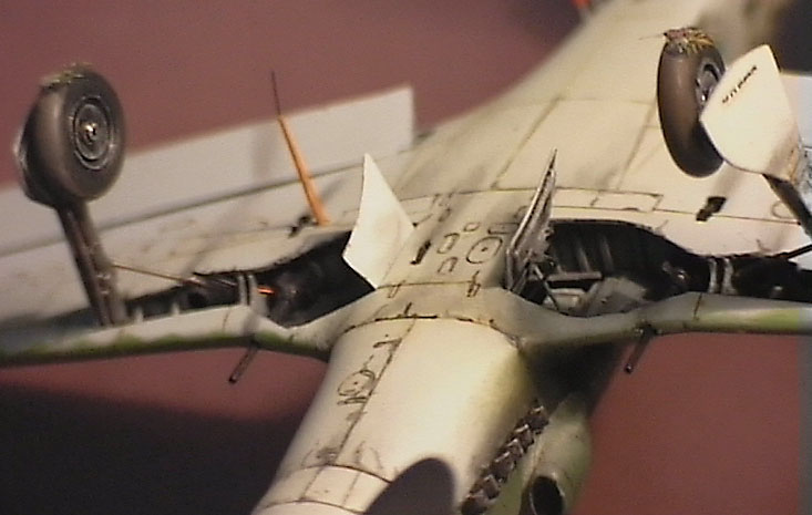
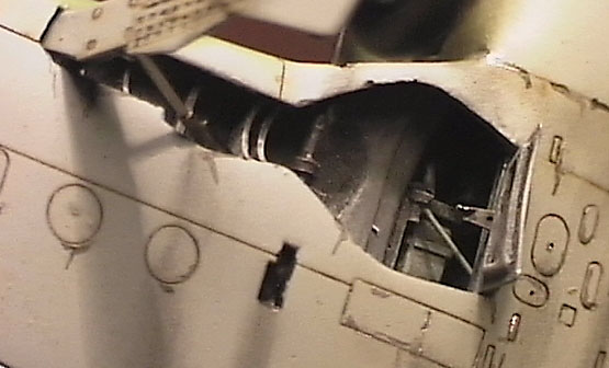
Exhaust Stubs Using the drilled holes as reference points, I thinned down the interior of the fuselage in this area till paper-thin. I marked out a rectangle to match the plans and opened it up. Construction of the individual exhaust stubs was quite easy but required some careful bending. I bent up the ejectors from thick hypodermic tubing, approx. 1 mm in diameter. I bent each to an angle of about 45 degrees taking care not to kink the tiny part, and then squashed the end (but not completely). I filed off and cleaned up to keep the stub looking hollow. I made 12 of these and mounted in a strip of plastic card spaced to fit in the exhaust aperture. The spacing is not regular and careful comparison to plans was required to get it right. The stubs were also spaced out from the backing to give correct protrusion outside the fuselage when fitted. Once complete they were painted and set aside for later fitting.
Radiator and Cowling The radiator cowling had to be changed in profile and the cooling gills removed so closed cooling gills could be scratchbuilt and fitted. After rescribing the cooling louvres in the top of the assembly was carved in place. As I said earlier, I scratchbuilt a radiator for the front of my cowl, not realising that this was incorrect at the time. In retrospect, I would have stayed with the standard Frog moulding in this area.
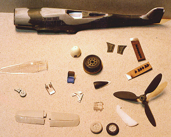
Propeller Blades and Spinner The propeller blades supplied are incorrect in profile, but unfortunately less so than those I had to modify for the kit. As the originals had disappeared in the mists of time, I used the prop from the Airfix D9 and after much building up and sanding down I eventually had a set of blades I was reasonably happy with. The method used was to stick a piece of 5 thou card to the area requiring broadening in profile, then fill the area between the card and the blade with super glue. After it has hardened, I filed away until the correct shape was achieved. This process had to be repeated several times. Constant reference to photos is required for this tedious task.
The spinner was sourced from the Italeri D9 kit and a hole for the MK 108 was drilled in the end. A backing plate was also added. Hindsight is a wonderful thing - I would now add a little filler to the front of the spinner and chuck it in a Dremel and turn it to a slightly 'blunter' profile, I would also add a short section of tubing to represent the cannon barrel. I also would paint it either, black or green 27 with a white spiral, not red.
Engine Detail The wheel wells on the Ta152 had no liners so the rear of the engine/supercharger/cannon breech and ammo boxes was visible. I scratchbuilt the extreme rear of the engine and all the other gear using the Trimaster kit as a pattern. Using scrap plastic, rod, lead wire, microstrip etc, and these components were built up and trial fitted, then painted, drybrushed etc and finally secured. The kit intake scoop was improved and a small cockpit air scoop was also added.
Wheel Wells The wheel wells were thinned down and new formers and main spar scratchbuilt. The wing cannon barrels were built from hypodermic tube and the mounts from plastic rod and strip. The brake lines and wiring looms were fitted and the whole painted, washed and drybrushed. Oleo legs were turned up from K&S brass tubing in my Dremel using files, sandpaper and a hobby knife. They were then detailed with mounting bolts, scissor links, brake lines from lead wire and stub axles. Again, painting, washing and dry brushing followed. The retract struts were built from hypodermic tubing and wire with hydraulic lines from lead wire. The original gear doors were used as templates to cut new covers from card, two each were cut, the second one to make the inner structure. After forming to the curves required, they were painted, (both sides) and finally assembled to the legs as one of the last items to be attached.
The inner doors were modified from the original kit parts. These were thinned down on the inner door area around the recess for the wheel and the operating mechanism scratchbuilt and then painted for assembly. The main wheels were scratchbuilt. Discs of thick plastic card were cut to the appropriate diameter with a leather punch and neoprene 'o' rings were purchased in the correct size. Section, rims for the hubs were made from rings of fine fuse wire and the centre 'dished' section of the rim was made from discs of thin card made with the trusty leather punch (a very handy tool I wouldn't be without, and no, I don't own a Waldron punch and die set - I wish). This disc was pressed into a soft surface in the centre with a rounded tool (a paintbrush handle if memory serves) and after a centre axle was made from some stretched plastic tubing and another very small thin disc of card. The wheels were then painted and assembled to the oleos after flats were sanded on the 'o' ring tyres.
Flaps The flaps were made using my own home brew etching process. Starting with K&S brass sheet, I drew up the flap design directly onto the brass with a scriber. Then I drew over the design with a felt tip 'resist' marker used for pc boards in the electronics industry. The brass was cut out and immersed in a warmed etching solution till the non-resisted brass was eaten through. This sounds simple but in fact was not particularly successful. The brass resisted areas were partially eaten away as well as the areas required as the resist pen was not very good. Anyway, after several attempts, I had two usable flap structures. There were fitted to two card outers and the whole assembly painted to represent bare metal and washed then drybrushed. The inner wing was detailed with strip.
The model was painted using Extracolour paints applied using a Badger 200. All the camouflage pattern and mottle was achieved using masks. The tail bands were sprayed. Decals are Microscale with the exception of the stencilling which came from an Almark set for the D9. The werknummer was hand painted onto clear decal film and all applied using the Microscale system including their original enamel Microgloss and Microflat. These are still the absolute best gloss and flat I have ever used with decals. It's a pity they don't make it anymore. A wash was applied using artists' oils and then weathering using pastels and Gunze 'oil'.
The parachute pack was made from an old 1/35 briefcase and straps from paper drafting tape with buckles from fine wire. The bicycle was made from fuse wire and scrap plastic.
Back to HyperScale Main Page Back to Features Index
|