Home
| What's New |
Features |
Gallery |
Reviews |
Reference |
Forum |
Search
Home
| What's New |
Features |
Gallery |
Reviews |
Reference |
Forum |
Search
|
|
|
Focke-Wulf
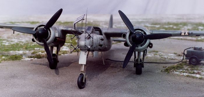
Ta 154V-3 by Larry Cherniak
I have wanted to build a model of the Ta154 ever since I first pored over William Green's "Warplanes of the Third Reich" in 1976. The pictures on p.243 were the reason-it looked so sleek, powerful, mean. With its unmistakable Kurt Tank/ FW design lineage and "coulda been a contenda" history, I was hooked. Fast forward a couple of decades and I've picked a good time to get back into the hobby, as Hasegawa has released a Ta154V-3 and a couple more fine 1/72 Ta154's. Pro-Modeler (you mean Revell and Monogram are the SAME COMPANY now?!) has obliged me also with a nice injection kit of the Ta154A-0 in 1/48 - the subject of this modification. The subject of the WOTR photographs was the third Ta154 prototype. Built mostly of wood, the V-3, W.Nr. 100003, was the first to feature Jumo 213 engines, armament (2 x 20mm and 2 x 30mm cannons), and radar (in the form of the FuG 212 Lichtenstein C-1 "mattress" array). Although it was also known as the Ta154A-03, the first pre-production prototype, the Pro-Modeler kit depicts a later A-0 with a different radar array, nosewheel geometry, antennae, and tailskid ("mysteriously" included in the kit- how long can it be before Dragon releases another version?). These are all "simple" modifications, although the radar was a severe challenge to my modeling skills. I also lowered the elevators, added the entry ladder, shortened the main gear, added open cowl flaps and surface detail of various sorts, and sprayed the main markings through plotter-cut stencils. As for the kit itself, parts location is positive (besides a few scoops and such which don't have locating holes), with nicely thick plastic and lots of mating surface area compared to the TriMaster/Dragon-derived kits. Detail on the fuselage aft of the wings is lacking; however many panel lines were taped and puttied over on the prototype so this may be considered accurate enough by some. Wing root fillets will at least need to be rescribed as they fade away to nothing, and it would look odd to apply fuel filler decals with no fuel filler caps around. The wings on my example were severely warped and needed internal reinforcement, but I understand this problem has been addressed in later pressings- it may have been a result of how the parts were packed in initial production runs. Overall, I really loved this kit. As mentioned in the review elsewhere on this site, it combines the finesse and accuracy of the Chinese Dragon moldmakers art with the very American sturdiness and engineering smarts of the old Monogram classics. I look forward to more kits in this "best of both worlds" style from R-M.
I started by gluing up in a flurry anything that fit together in two halves or made an easy subassembly without painting - engine nacelles (make sure to add LOTS of lead here), rudder, wheels, air scoops, etc. I find this early progress gives me a psychological boost as well as speeding production. I separated the solidly-molded elevators by scoring backwards with a no.11 blade, angling these cuts about 45 degrees to provide a nice undercut into the (two-part) stabilizer. If you choose not to separate the elevators, keep in mind that the join on one side will face up, so try to make it match the molded-in separation on the other side. The cannon-panel inserts were carefully glued into the nose. The wings on my example were warped, exhibiting a distinct anhedral droop as well as twist. I twisted them back until the plastic started to stress fracture, then epoxied a craft (i.e. Popsicle) stick spar toward the center of each upper wing half, clamping them straight as the epoxy hardened. I left glue off of the inner 1 -1/2 inches or so and, once hardened, propped this end up with another thickness of wood beneath. This provided tension and ensured a straight flat dihedral, reinforced when the lower wings and engine nacelles were glued in place (after notching with a file to clear the spar). Gaps around the nacelles were filled with a white glue and paint mix squeezed from an applicator bottle with a hypo tip.
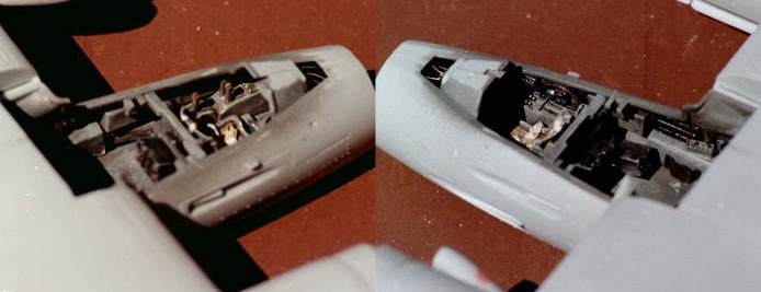
Altogether, fixing the warped wings was a 1-1/2 hour sidetrack that I really shouldn't have had to do and represents by far the kits worst flaw. I do hope the manufacturer has fixed this frustrating problem as I have heard. On the bright side, I now have a more accurate model-it has real wooden wing spars, just like the prototype! I found the cockpit well detailed in the front office (although details of the right side console did not seem to correspond to the photo or diagram in reference #2) a little barren in the back. I didn't waste a lot of time detailing the instrument panel, as it is buried deep under the hood when assembled. The back of it can be seen, however, so I added a few wires and tubes back there. I also added seat supports (small rectangles of metal connecting the FW190-style seats to their rails), belts, and some "creative gizmology" to help fill out the rear area. This included some horizontal "wing spar" structure to the flat area at the back and a couple of plates to blank off the wing roots.
The cockpit was painted with acrylics, mostly Polly Scale Guilford Grey as scale RLM66, so that oil washes could follow soon after drying. I glued some cannon barrels into the lower openings and blocked them off to light before installing the cockpit. Of course one fell off and had to be fished out- the first of several "moments" I had with this project! The fuselage went together well but the wing-to-fuselage joint, engine scoops, and the clear shoulder window piece all needed some filler. The radar hood was left off until after painting to ease masking and the engine fronts and cowl rings were tacked on until after the cowl flaps were installed (about which more later).
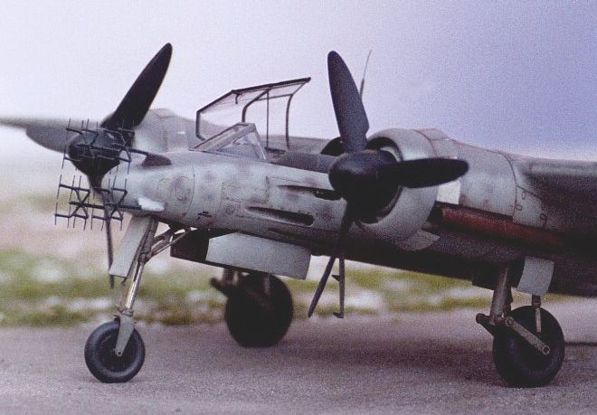
The nosewheel needed to be backdated by sawing out the forward extension kink above the fork. Although I did this with the fork CA glued together and later snapped apart to install the front wheel, it may have gone better with the wheel in place before cutting and shaping. I chose to extend the oleo to give the nose-up stance I liked in the photographs in reference #1, so added a length of brass rod covered with chrome Mylar, using the extended length of the modified kit oleo link as a guide.
I like the look of open cowl flaps so decided to add them. I simply painted the kit pieces black, except for the half-width flaps just below the exhausts, and designed the flaps a little long to cover up the opening. I designed and made the cowl flaps at work with an illustration program and a computer-controlled plotter/cutter, which was used to cut 4 mil matte chrome Mylar with a carbide blade -just like the vinyl companies do. After some experimentation and thought I came up with a rather clever (If I do say so myself!) two-thickness arrangement with a different cut on each layer, the lower layer left unpainted. The results were four separate self-adhesive curved parts, simply painted and wrapped into place, with a little CA glue run in for good measure. These were rather delicate and were left off until late in finishing.
The surface detail was enhanced with some rescribing, particularly the wing roots and the tail, and the addition of gas filler caps and the like from plotter-cut 2-mil vinyl. The various plans and boxtop art all varied in specifics, so I made educated guesses and compromises and scribed away. The separation line between fuselage and tail should be puttied and taped over, as is visible in photos. I carved detail into the flat area at the top rear surface of the tail, based on a photo in reference #2. The alternative tailskid included with the kit, part A5, was used and the D/F loop was left off. I could find no photographic evidence of the small engine air scoops, parts E3, being present on the V-3, so left them off also. The oversized reinforcements along the spine were replaced with thinner strips. The raised hinge lines on the upper wing were enhanced by cutting a line across them every two scale inches, and hinges were added to the top of the engine cowls. These were thin strips of Mylar with lines drawn across them with an extra fine marker. I detailed the landing light area with a rib in the center, "brass" (gold Mylar) reflector, MB lenses, and clear acetate covering. The entry ladder was made from .020 sheet stock and glued to the end of a trough I had earlier scribed and scraped -with the end of a snapped off #11 blade- into the underside of the nose (using the kit panel lines as a guide).
Painting was begun by priming with Floquil Military Colors light gray primer then airbrushing freehand with RLM 74, 75, and 76 Modelmaster enamels scale-lightened with semigloss white, allowing some of the primer to lightly show through in a patchy manner.
As I was representing a well maintained but well-used prototype, weathering was kept light except for heavy exhaust stains as per photographs. The vertical tail was repainted on the prototype so I tweaked some RLM75 a little darker for it. The rudder was sprayed with this mixture and the mounting lugs trimmed for a slight turn (after R-M kindly replaced, gratis, the one I lost in transporting the model to and from work for test-fittings. They would later replace the canopy I stepped on- the other "moment").
If you have read this far, you probably know the finishing drill already-wet sand with Flexi-Grit, varnish with Future, wet sand, decal, Future topcoat, wet sand, Modelmaster Acryl flat varnish, earthtone oil washes, silver pencil on the metal areas, etc. By the way, the sanding not only smoothes out the finish but actually cuts through the paint here and there as a form of weathering, very accurately replicating wear.
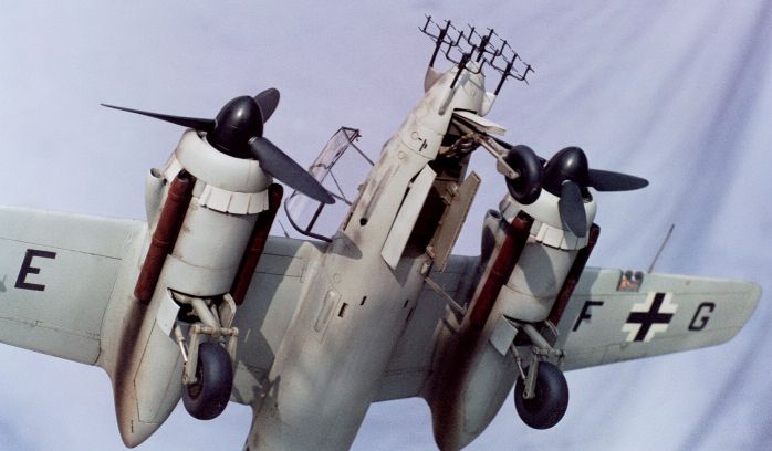
Now the fun part- scratchbuilding the antennas array. The Germans called this FuG 212 Lichtenstein C-1 configuration the "Matratzen" or "mattress" array, and I now know why. What a nasty set of bedsprings it was to try to replicate- 32 aerials on 8 "fingers" on four faired stalks.
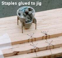
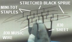
First I made a scale drawing to work out the proportions. Then I used music wire bent and inserted through holes drilled in the nose piece, 0.030-sheet stock, and much puttying and sanding to add the "stalks" and fairings. The extra radar mounting holes and corresponding panel lines were filled at this time and the nose filled with epoxy and Bb's. The nose was now tacked onto the model for painting and varnishing. The second step was to solder together four sub-assemblies from mini staples-it saved me much trouble having a premade shape to work from. I made a simple jig by marking a square on a piece of balsa wood, sticking two staples in it at the corners, lining up their centers (I had previously marked them with a line down the middle of the row of staples) and soldering. Using solder flux and 0.015 silver solder, I built up eight pairs in short order and kept the best four. Next these subassemblies were CA glued to a wooden jig so they wouldn't come undone when I soldered them to the nose stalks. They needed perfect orientation if the 32 final wires were to line up. Once soldered on, releasing them from the CA was not as easy as I had anticipated. Soaking in debonder and acetone for 10 minutes didn't budge them (perhaps the heat super-cured it?), so I ended up cutting the wood away and scraping the remnants off. In retrospect, white glue might have worked better.
Now 8 lengths of stretched sprue (fishing line or something else more resilient might have been better) were CA glued vertically in four places each and snipped apart with surgical scissors into 32 pieces, using a square toothpick as a guide. Finally, short lengths of music wire with their noses pointed were glued to the front center of each staple assembly to complete the forward extension of the stalks. The nose was finally masked off and the whole array was sprayed black-green.
This kit is a fine starting place for an excellent representation of a rare and unusual bird. While it is perhaps not state-of-the art, I look forward to more in its agreeable style from Promodeler. Removing the wing warp is a stumbling block but within the skills of the average modeler. I would recommend waiting for Dragon to possibly release the Ta154V-3 with some photoetch, look for aftermarket aerials, or take on one of the day fighter subjects if you're looking for something a little different from your kit. Building a radar array like this is only for the most dedicated or masochistic. I wouldn't have spent this much time and effort unless I had a special desire to see this subject on my shelf, and am very happy to have it there now, looking just like I had pictured it in my head at the beginning of the build. Now that's satisfying! I would like to thank the good Hyperscalers who responded to my requests for information online, especially Helmut Latoschinski who Emailed me the much needed Hasegawa paint diagrams from Germany. Thanks guys! If there are any corrections or comments let me know.
There are monographs available on the Ta154 but I don't have them, relying instead on small parts of more encyclopedic works in my library like: 1) The Warplanes of the Third Reich, William Green, Doubleday, p.241-245 2) German Aircraft Interiors, Vol. 1, Kenneth Merrick, Monogram Aviation Publications, p.156, 157 3) The Luftwaffe Album, Dressel and Griehl, Brockhampton Press, fighters p.122-124 4) Focke-Wulf: an Aircraft Album No.7, J. Richard Smith, Arco p.87-90 5) Nightfighters Over the Reich, Manfred Griehl, Greenhill, p.52-54
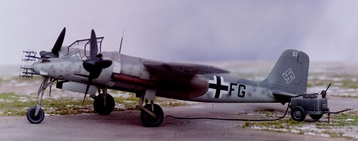
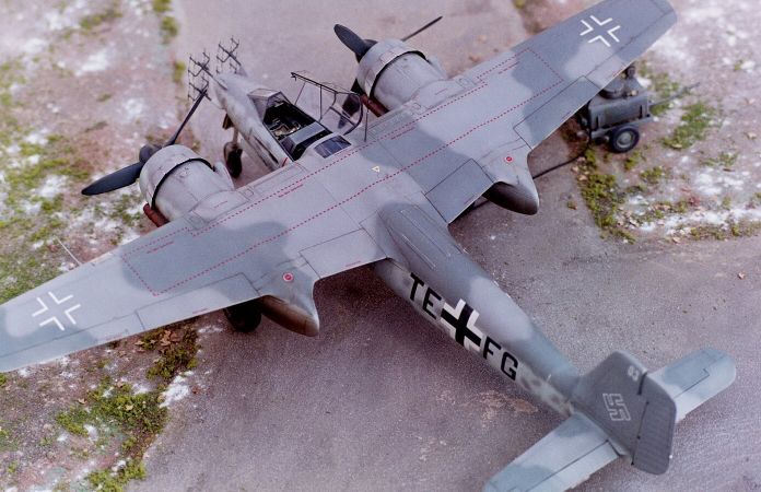
A word about the pictures. They were taken with my trusty Minolta with 50mm and 80-200mm lenses on a hastily constructed "forced perspective" airfield base.
This was a wedge-shaped sheet of plywood about 3 feet deep with brown paint ground fading to light gray toward the back. The fuel cart is ProModeler, the backdrop is a sheet (gotta get the wrinkles out next time). My first roll was underexposed due to operator error but the results were interesting, I think. The grainy, faded shots reminded me of newly discovered WWII color and became my favorites. Now I'll have to practice replicating that look in software!
Click
on the thumbnail images below to view full sized.
Model, Text and Images Copyright © 2000 by Larry
Cherniak
|
 The
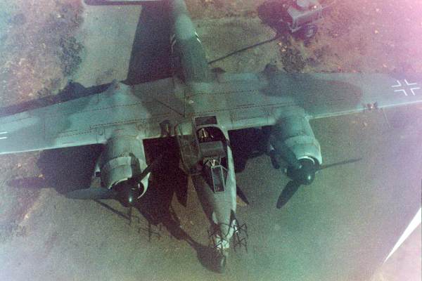
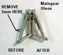
maingear would need to be shortened to achieve the correct squat attitude even
if I hadn't extended the nose gear. I cut about 1/16" or so from the top of
each of the four oleos, bent them out a bit, and reglued them while test-fitted
together with the maingear legs. Mechanically this works just as the prototype
gear worked, changing the angles realistically. Filing a flat spot on each tire
helped also.
The
maingear would need to be shortened to achieve the correct squat attitude even
if I hadn't extended the nose gear. I cut about 1/16" or so from the top of
each of the four oleos, bent them out a bit, and reglued them while test-fitted
together with the maingear legs. Mechanically this works just as the prototype
gear worked, changing the angles realistically. Filing a flat spot on each tire
helped also.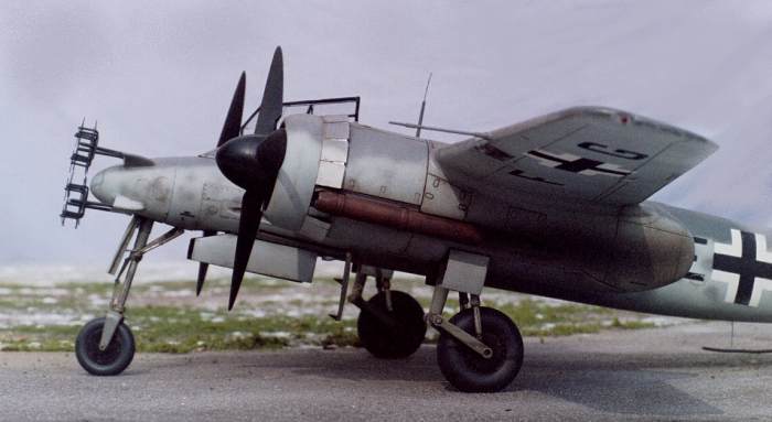
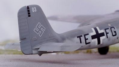
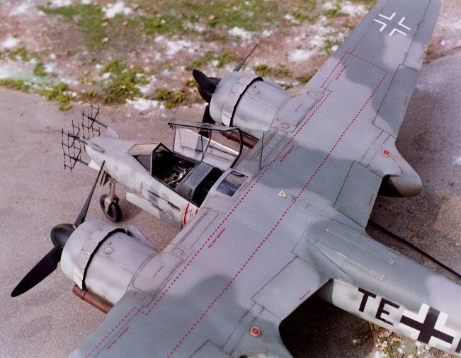
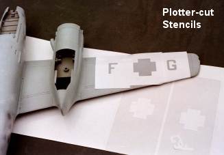 Since
I didn't have the right code letters in my decal collection and I was
curious about how it would work (and because I could, having free access
to a $15,000 plotter/cutter at work!) I chose to cut my own stencils and
spray on the national markings and codes. These were designed on computer
and plotted out of a low-tack paint-mask vinyl. Once these were applied to
the model, white was sprayed on the Balkenkreuzen in several light passes.
Next the corners were masked over with the cutouts (except for the upper
wing, which was now done) and sealed back together with the rest of the
paint mask with liquid masking agent. Scale black was sprayed next, and
the mask removed.
Since
I didn't have the right code letters in my decal collection and I was
curious about how it would work (and because I could, having free access
to a $15,000 plotter/cutter at work!) I chose to cut my own stencils and
spray on the national markings and codes. These were designed on computer
and plotted out of a low-tack paint-mask vinyl. Once these were applied to
the model, white was sprayed on the Balkenkreuzen in several light passes.
Next the corners were masked over with the cutouts (except for the upper
wing, which was now done) and sealed back together with the rest of the
paint mask with liquid masking agent. Scale black was sprayed next, and
the mask removed.