|
British
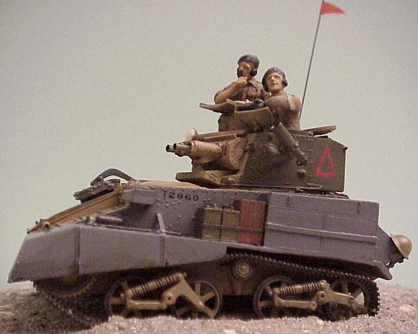
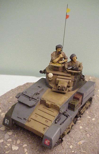
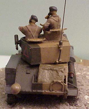
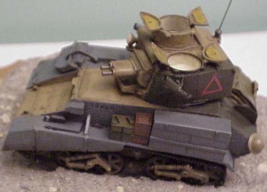
Vickers VI B Light Tank
Cromwell Models #CK 13
by
Brian Bocchino
|
Vickers
VI B Light Tank |
History
Between World War I and World War II, the British designed 3 classes of tanks: Light,
Infantry, and Cruiser. The Light tanks were to be used for Reconnaissance; Infantry tanks
would support the Infantry while being slow and heavily armored; Cruiser tanks were
designed to be fast and used for mobile warfare.
When England launched its rearmament program in 1936, only the Vickers Mark VI series was
available for mass-production. By 1940, 1218 Mk VI series tanks were produced; of which,
the Mk VI B was the most numerous, totaling 874 vehicles. These vehicles were used to
equip the Royal Tank Regiment (RTR) and the mechanized cavalry. By 1941 most of the Mk VI
series tanks still in service were B models. These vehicles saw service in both France
with the British Expeditionary Force (BEF) and in North Africa. This vehicle had a crew of
3 and by 1942 these vehicles were withdrawn and replaced with U.S. Stuart tanks as rapidly
as possible.
The withdrawn vehicles were then converted into Anti-Aircraft vehicles that mounted
either quadruple Besa 7.92mm machine guns or two Besa 15mm guns.
 The Mk VI, VIA, and
VIB all were armed with one .303 inch and .5 inch Vickers machineguns. 200 rounds of Armor
Piercing ammunition was carried for the .5 inch and 2,500 rounds of ball ammunition for
the .303 inch. The vehicle was fitted with external smoke projectors on the turret, and a
wireless transmitting-receiving set in the turret. The turret could traverse by using a
hand mechanism. The vehicle had armor protection against .303 inch rounds. They weighed
5.2 tons and had a maximum speed of 30 mph. Only minor alterations were made between A and
B models. Most of these changes dealt with the cooling system and ventilation. The C model
differed in armament, ammunition, and in the cupola. The armament was changed from the
Vickers to the Besa 15mm and 7.92mm machineguns. Ammunition storage consisted of 175 AP
rounds for the 15mm and 2,700 rounds of ball ammunition for the 7.92mm. The commander's
cupola was replaced with a split hatch containing a periscope. Initially the Vickers VI
series of tanks carried Number 7 wireless sets, but were quickly replaced with Number 19
sets. The No 19 allowed satisfactory communication for the first time between all crewmen. The Mk VI, VIA, and
VIB all were armed with one .303 inch and .5 inch Vickers machineguns. 200 rounds of Armor
Piercing ammunition was carried for the .5 inch and 2,500 rounds of ball ammunition for
the .303 inch. The vehicle was fitted with external smoke projectors on the turret, and a
wireless transmitting-receiving set in the turret. The turret could traverse by using a
hand mechanism. The vehicle had armor protection against .303 inch rounds. They weighed
5.2 tons and had a maximum speed of 30 mph. Only minor alterations were made between A and
B models. Most of these changes dealt with the cooling system and ventilation. The C model
differed in armament, ammunition, and in the cupola. The armament was changed from the
Vickers to the Besa 15mm and 7.92mm machineguns. Ammunition storage consisted of 175 AP
rounds for the 15mm and 2,700 rounds of ball ammunition for the 7.92mm. The commander's
cupola was replaced with a split hatch containing a periscope. Initially the Vickers VI
series of tanks carried Number 7 wireless sets, but were quickly replaced with Number 19
sets. The No 19 allowed satisfactory communication for the first time between all crewmen.
Use in Africa: On 1 March 1941, the British reported the following number of light
tanks in the Middle East: 36 Mk VI, 55 Mk VI A, 276 Mk VI B, and 1 Mk VI C. Of the 368
total Mk VI tanks, 149 belonged to the 7th Armor Division and 169 to the 2nd Armor
Division leaving 50 unaccounted for - possibly war reserve. Trying to trace who had these
tanks is difficult, but here is what I have found. In the 7th Armor Division, the 7th
Brigade had 7 VI B light tanks, B Squadron, 4th Brigade 1 VI C. The 2nd Armor
Division, 1st Brigade had 3 VI B, and 3rd and 4th Hussars had 52 VI B each.
Sources
Tank Combat in North Africa, The Opening Rounds by Thomas Jentz, ISBN:
0-7643-0226-4
AFV Profile #5, Light Tanks Marks I-VI by Major General N. W. Duncan
Museum vehicles: Aberdeen, MD, USA; Bovington, UK; Borden Museum, Ontario, Canada, Saumur
Museum, France. I'm sure other examples exist, but here are 4 well know museums that have
one.
G e
n e r a l O b s e r v a t i o n s |
If you have never built a full resin kit, this should not be your first one. While the
castings are overall very good, there is an excessive amount of flash and over pour that
must be removed. There are several very delicate parts as well. In my humble opinion, the
perfect first time all resin kit for a modeler should be one of the kits offered by On
Track Models. Also compounding the construction is the general level of vague instructions
common to nearly all resin kits. Looking back at the completed process, I enjoyed building
this kit because it required me to use all of my skills.
 Construction
starts with the lower hull and road wheel assemblies. Construction
starts with the lower hull and road wheel assemblies.
The hull has a large rectangular opening in the bottom to which the resin pour was done
from leaving a large rectangular plug all the way around the opening that has to be
removed. Most people would probably saw this off, but I chose a different route, I took my
dental pick and scribed a seam line and then use a pair of pliers (jaws type) to snap of
the rectangle plug. The hull base plate that fits in the rectangular opening in the bottom
is not installed until the last step. However, by then all the delicate parts are already
on the model, so I elected to install mine in the beginning, fill the seams, and sand
flush. This worked quite well giving me a flush cut and eliminating a lot of resin dust
that would have been created by sawing.
For the road wheels, I took my Dremel chuck and mounted the wheels in them for sanding.
The center hole is slightly smaller than the screw for the chuck, but I just screwed them
through it after drilling a larger hole in a block of wood to use for support. This
allowed me to lay the wheel flush on the wooden block while inserting the screw into the
wheel. Sanding the wheels this way kept them 'round', but I also discovered several air
holes lay just under where the stems meet up with the tires. Some simple putty fixed
those. The other discovery was that the flash between the stems/spokes was often not
flash, but fairly thick resin. I used my knife to cut out/remove the flash. When building
the assemblies, it's important to look closely at a real suspension. There is a lot of
overflow that is hard to distinguish between what is really small detail versus what is
actual overflow. I also wound up replacing several of the axles with copper wire because
they were either deformed or not long enough. The wheels can be tricky to attach. There is
a partial indentation, which lacks support. If you're not careful, your road wheel
assemblies won't be in line when you go to attach the tracks. My solution to this was to
remove the stub from the wheel assembly are replace it with wire. I then drilled all the
way through the partial indentation into the hull. This provided both support and
alignment.
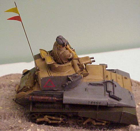 Prior to attaching
any road wheels, you need to decide if you are building a desert or a European version. If
you are building a desert version, look at the 2nd step to see which fittings must be
removed from the one side to mount the large toolbox. Removing them now will be easier
than trying to remove them later after detail/delicate parts have been attached to the
hull. As a side note, the resin pour plug for the toolbox is located on top, which I
consider to have been poorly placed. Prior to attaching
any road wheels, you need to decide if you are building a desert or a European version. If
you are building a desert version, look at the 2nd step to see which fittings must be
removed from the one side to mount the large toolbox. Removing them now will be easier
than trying to remove them later after detail/delicate parts have been attached to the
hull. As a side note, the resin pour plug for the toolbox is located on top, which I
consider to have been poorly placed.
Extra care must be taken when building a desert version. The shields are thin and form
a boxed "L" in front. Use a brand new blade to carefully and slowly remove the
resin plug without damaging the shields.
The tracks are really kind of horrible. They have a lot of flash and some of the link ends
are solid resin in-between. Much care must be taken when cleaning them. I used a
combination of an X-acto knife, dental picks, thread, and a pin vise drill (of which I
broke one bit while working!) to remove the flash as best as possible. Still, the tracks
do not clean up very nicely. If building the desert version, the sand shields can hide at
least one length of track. Four lengths of track are needed for each side (one length will
be cut in half at the end, you only need 3.5 lengths). At first, I approached it by gluing
two lengths together and sliding along the top of the wheels. I then cemented the track in
three places, the top of the drive sprocket, Return Wheel, and guide wheel. Afterwards,
using toothpicks I created sag and added a little cement to hold the form. Then with a
hairdryer, I heated each end separately and bent around the wheels. Yes, heating resin
track with a hairdryer really does work. Next I attached the bottom length of track using
the same method. For the second side, I found it easier to glue all four lengths together
and slowly working into shape with a hairdryer. This method work far better. This time I
started about an inch back from the top of the Drive wheel and worked towards the rear.
Using the hair dryer, I carefully bent the track around the rear wheel and moved towards
the front. With more heat of the hairdryer, I heated the remaining lose track to the point
that it was almost like string. This allowed me to bend the remaining track at a sharp
angle to fit over the drive sprocket and under the fenders.
 Once the track
had finished setting, I placed the model on a tile (which I use for cutting photo-etch
on), and examined the tracks/suspension from the rear to check for crookedness. Using the
hairdryer once more, I heated both the track and suspension to align them. This fixed the
alignment problem. Once the track
had finished setting, I placed the model on a tile (which I use for cutting photo-etch
on), and examined the tracks/suspension from the rear to check for crookedness. Using the
hairdryer once more, I heated both the track and suspension to align them. This fixed the
alignment problem.
The driver visor on the hull was very soft. Painting would have completely hidden the
detail. I made a new visor out of plastic card.
There are two box lights that go on each side of the hull; on the rear facing side,
they each had a stem sticking out. Comparing the boxes with real pictures indicated that
it was thin sheet metal and the rear side had a hole to access the inside with. A bit from
the Dremel rectified this problem. There is an access hatch with a lever mechanism just
left of the drivers' area in which the arm travels along a bracket connected by a bolt.
This was poorly cast, so I made a new one out of sheet plastic using a scriber to open a
gap. A new handle was made from sheet plastic and some Grandt Line bolts. The hinges for
the access plate are missing, so I added them from wire and some scrap photo-etch pieces.
The turret did not sit quite flush onto the hull. This was mainly do to the fact that I
left the huge plug on the bottom of it for added weight. To rectify this, I took my Dremel
and just went around the edges of the plug until it would fit evenly through the whole in
the hull. When sanding/cutting resin with my Dremel, I use a small vacuum cleaner with a
hose. This captures most of the dust and makes for a safer environment.
 While the kit has some
rough spots, I would still recommend it if you desire a Vickers Light Tank for your
collection and can not wait for the one that will supposedly be released in plastic from
an Eastern European country in the near future. While the kit has some
rough spots, I would still recommend it if you desire a Vickers Light Tank for your
collection and can not wait for the one that will supposedly be released in plastic from
an Eastern European country in the near future.
Model, Description and Images Copyright © 1999 by Brian Bocchino
Page Created 17 April, 1999
Last Updated 26 July, 2007
Back to HyperScale Main Page
Back to Features Index
|
 Home
| What's New |
Features |
Gallery |
Reviews |
Reference |
Forum |
Search
Home
| What's New |
Features |
Gallery |
Reviews |
Reference |
Forum |
Search