|
|
|
Douglas A-4C Skyhawk |

Hasegawa's 1/48 scale A-4C Skyhawk
is
available online from Squadron.com
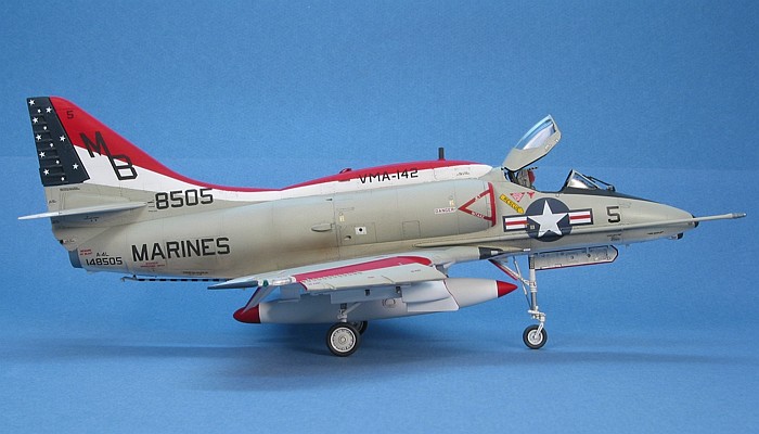
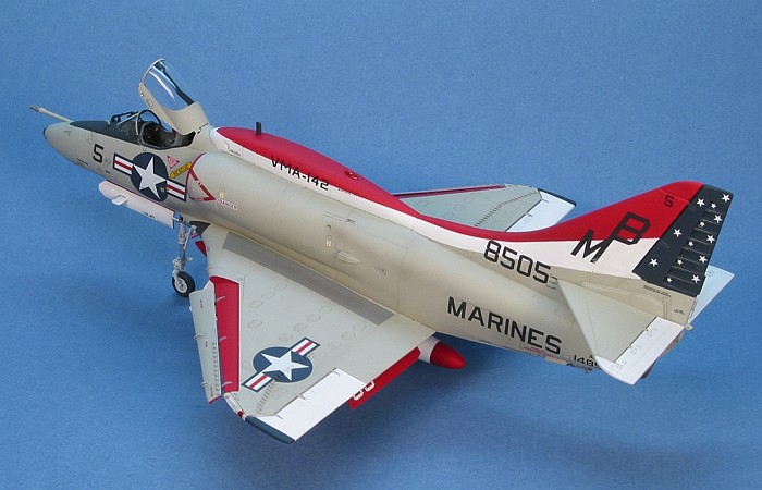
The US Bicentennial celebration was good for creating many
colorful and decorative paint schemes on US military aircraft. This VMA-142
machine is one of my favorite A-4 Skyhawk Bicentennial schemes. Actually, this
is one of my favorite Skyhawk paint schemes, period -- Bicentennial or
otherwise.
Note that the year of the US Bicentennial (1976) marked the
year that VMA-142 transitioned into A-4F "Super Fox" Skyhawks. Hence, this
markings scheme adorned both an A-4L and an A-4F "Super Fox" aircraft.
Converting Hasegawa's
Skyhawk to an A-4L
|
The basic kit for this project is the Hasegawa A-4C
Skyhawk. Like the A-4E kit that was released before it, lots of extra parts are
found in the box to allow the modeler to build most any variation on the A-4C
airframe. The A-4L is an upgraded version of the A-4C that basically brought the
A-4C up to the same avionics configuration as the A-4E and A-4F. Part of this
upgrade included the fitting of an avionics hump similar to the one found on the
A-4E and A-4F. Also included were many of the radar and radio antennae found on
the A-4E and A-4F.
The following procedure converts the A-4C kit into an A-4L.
Note, again, that all these changes use parts that are already present in the
kit. These parts are "grayed out" on the instruction sheet as being not used (on
the A-4C), but they are the right parts to use to update the A-4C to an A-4L.
The step numbers relate to the Hasegawa A-4C kit instruction steps:
-
Before assembling the nose halves, open the
flashed over hole (half the hole is on each half of the nose) in the middle
lower portion, along the seam between the two parts.
-
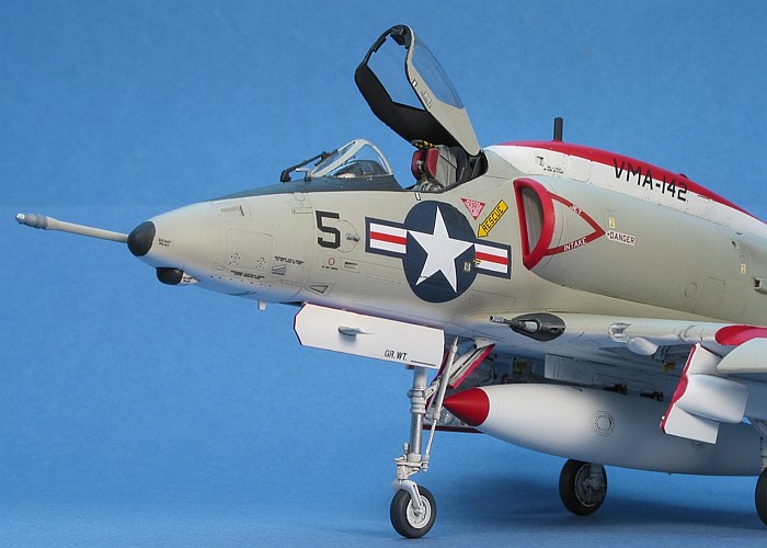
After assembling the nose, attach the nose
mounted ALQ-51A/100 ECM antenna (kit parts D19 and E31) into the hole you
just open on the bottom. For the specific aircraft I was building, the
fairing is present without the "spike" antenna. I attached the fairing (part
D19) and ommitted the spike (part E31).
-
Do not attach the cover plate (part A12) on top
of the fuselage. You need this part to cover the opening on the top of the
avionics hump.
-
Fill in the small vent on the right rear
fuselage, just ahead of the speed brake well. This vent pertains to J52
powered aircraft (A-4E and later). Drill out a new vent hole in the same
location that is only about one third the diameter of the hole just filled.
Instruction Step 5
-
Assemble the avionics hump (parts D13 and D14).
-
Use the cover plate (part A12) to fill the
engine beed air vent hole in the top of the avionics hump. Fill and sand the
area to be smooth without any panel lines marking the position of the vent
hole.
-
Open the locator hole for the upper COM antenna
in the forward section of the hump. Attach the COM antenna (part E11) in the
upper COM antenna hole in the forward section of the hump.
-
File off the two scoops on rear portion of
either side of the avionics hump. Fill and smooth the holes remaining after
the removal of the scoops. These scoops pertain to J52 powered aircraft
(A-4E and later).
-
Do not attach the forward tail piece (part
A13). In its place, attach the now assembled avionics hump.
-
Do not fill the panel lines around the engine
exhaust as indicated in the inset diagrams. Use these panel lines to locate
the attachment points for the tail mounted ALQ-51A/100 ECM antennae. Parts
D17 and D18 go on the sides of the engine exhaust. Part E19 goes under the
exhaust. For the specific aircraft I was building, the fairing (part E19) is
present without the "spike" antenna. I attached the kit part, then hacked
off the spike.
-
Do not use the smooth lower fuslage piece that
has no chaff dispenser (part A6). Instead, use one of the lower fuselage
pieces that have a chaff dispenser (parts A7 or A8).
-
Check your references for the exact aircraft
you are building -- the small antenna on top of the fin cap (part A15) is
present on some A-4Ls.
Instruction Step 8
-
Attach the mid-fuselage ALQ-51A/100 ECM
antennae (parts F22) to either side of the rear portion of the nose wheel
well. There are two small scribed rectangles in this area. One antenna gets
mounted over each rectangle. For the specific aircraft I was building, the
fairings are present without the "spike" antennae. I attached the kit parts,
then hacked off the spikes.
Instruction Step 9
Instruction Step 11
-
Attach the rear tail mounted ALQ-51A/100 ECM
antenna (part F21) to the trailing edge of the vertical tail, centered over
the spot where the rear edges of the horizontal tails are found. For the
specific aircraft I was building, the fairing is present without the "spike"
antenna. I attached the kit part, then hacked off the spike.
-
I could find no confirmation concerning the
underside chaff dispensers (parts A5). Since the rest of the avionincs suite
was brought up to A-4E/F standards including the rear fuselage chaff
dispenser, I would tend to think that these dispensers were probably added,
also. For my model, I was not sure enough to add them and chose to use the
plugs. If you choose to use dispensers, attach them (parts A5) in place of
the chaff dispenser plugs (part A3 and A4).
Instruction Step 13
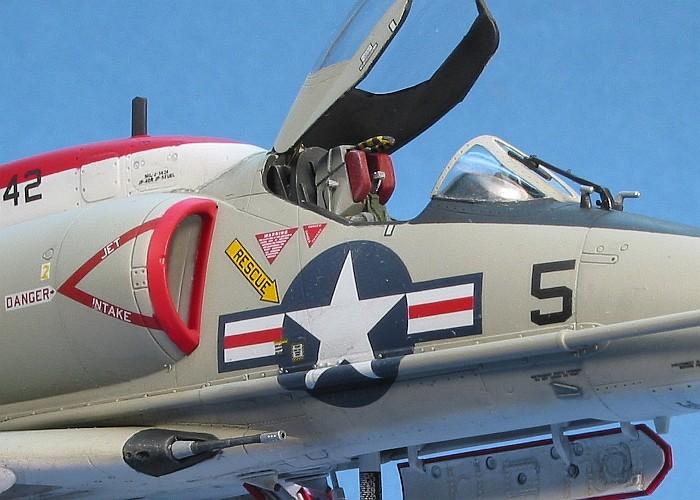
One other change I made to the kit (that was not in the
box) involves the use of an after-market ejection seat. While adequate, the kit
provided ejection seat is a bit simplistic. So, I replaced the seat with one
from Cutting Edge.
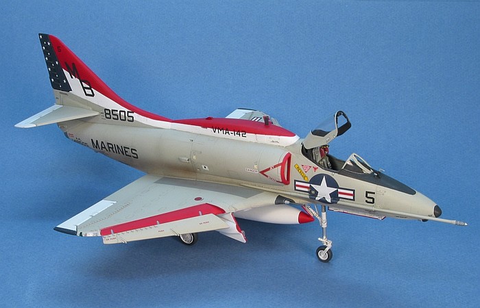
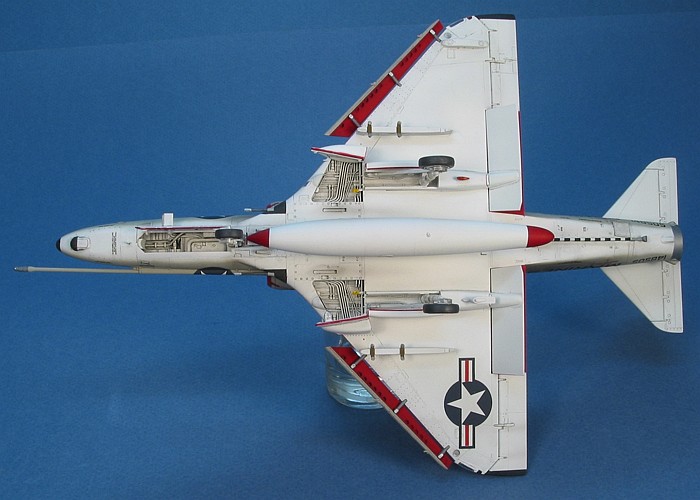
As this is a bit of a "show bird" in its Bicentennial
markings, I chose to keep the weapons load limited to just an external fuel
tank, as provided in the kit. Attaching the tank highlighted a "gotcha" in the
kit that I have not found until I tried to hang a fuel tank on the centerline
weapons pylon. Note that the centerline weapons pylon is not quite symetrical
and definitely has front and back ends. The instruction sheet is unclear which
end goes forward. I seems I have been attaching the pylon backwards in all my
Skyhawk builds to date.
Looking at the pylon, note the two cut-outs for the sway
braces are slightly closer to one end of the pylon than the other. The front end
of the pylon is the end where the cut-outs are farther away. If you
attach the pylon backwards and go to hang a kit supplied fuel tank on the pylon,
it will hit the nose landing gear. Trust me on this.
I found the problem after my model was completely
assembled, painted, decaled, and weathered. The pylon was too well attached to
pop off and re-attach correctly. Hence, I decided I should just machine in two
new cut-outs for the sway braces at the correct locations (if the pylon was
attached right) and mount the fuel tank in these new cut-outs. I did not want to
risk damaging the existing paint or weathing by trying to fill the original
cut-outs. So, if you look closely at the centerline pylon, you can see the
kit-provided sway brace cut-outs still present on the pylon. Oh well...
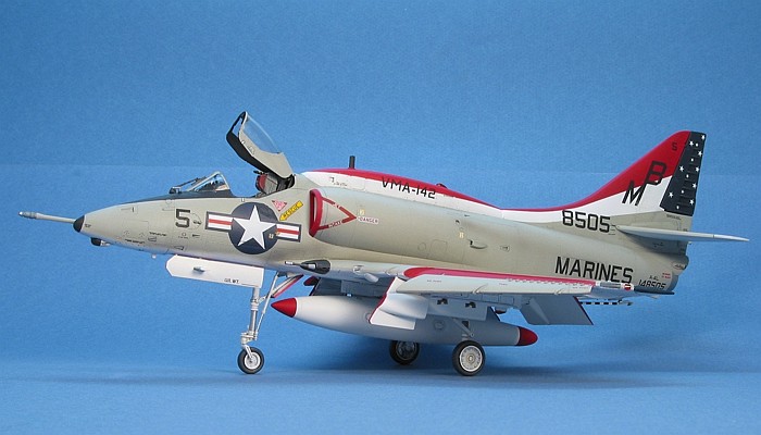
The camouflage on the model is the old standard of Light
Gull Gray (F.S.36440) over a white bottom with the tops of the flight control
surfaces also being white. I painted the white first and masked off the flight
controls, then I painted the Light Gull Gray. I sprayed the line freehand
between the gray and white along the fuselage sides.
The decals on the model are from one of the Eagle Strike
decal sheets released last summer (stock#48-033). I wanted to build a model of
this aircraft ever since the 1980s when SuperScale released a 1/72nd
scale set of markings for it. I was planning on creating my own decals when I
found the Eagle Strike decals at the IPMS Nationals in Chicago. I did not
want to argue with fate and bought a set on the spot.
The sheet provides the white portion of the hump and tail
markings and expects you to paint the red and blue. Since the decal instructions
claim the decals are really intended for the Hobby Craft kit, I feared
that the white decals would not fit the considerably different sized Hasegawa
kit. I chose to mask and paint all of the red, white, and blue portions of the
hump and tail.
I also replaced the decals for the tail code, large BuNo
numbering, and MARINES text with new decals I printed myself. The Eagle
Strike renditions of these markings were not to my liking, being not bold
enough and (in the case of the tail code) quite irregular. As all these markings
were only printed in black, I printed them on my laser printer (no ALPS needed).
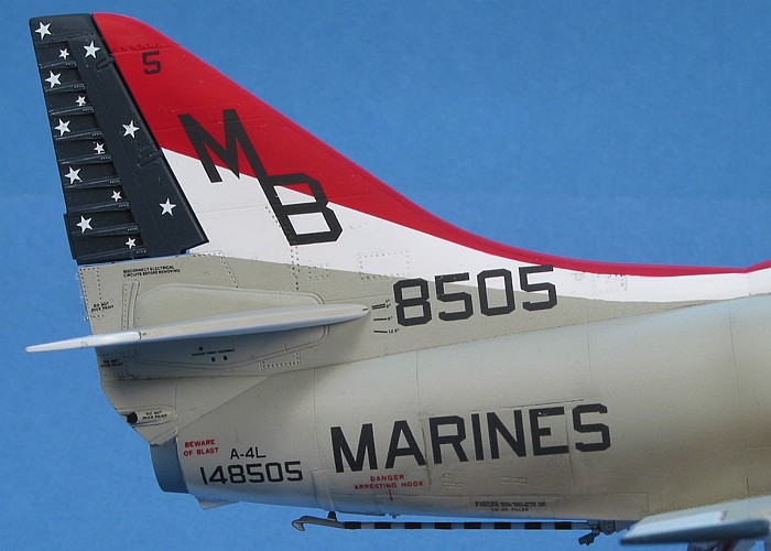
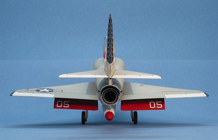
Another shortcoming of the sheet involves the stars on the
rudder. There should be thirteen stars on each side. The instruction sheet draws
thirteen stars on each side. The decals only provide twelve. Oops! Not to fear,
the picture I found of this aircraft also shows that five of the stars are
supposed to be smaller than the others. Eagle Strike provides all one
size. I secured a set of smaller stars from an old SuperScale sheet and
used these in addition to the Eagle Strike stars. I ended up with four
extra Eagle Strike stars from each side of the rudder that I could add to
my decal scraps box.
Another place it seems that Eagle Strike has trouble
counting concerns the red stripes which they print separately from the white and
blue national insignia. Don't get me wrong, I like the separate stripes because
it lets me control the register of the stripes in the insignia. However, the
sheet provides eight national insignia and only six sets of red stripes.
As I was building two Skyhawks at the same time, I needed
all eight national insignia. Fortunately, I was able to compensate from a
different Eagle Strike A-4 Skyhawk sheet (stock#48-032) which also has
eight national insignia and twelve sets of red stripes. Someone must have
been asleep when these sheets were inspected for completeness.
For weathering, I used my typical style of thinned down
enamel paint washes and air brush shading. I finished the weathering with some
dry brushing to pop out the surface details. For a more complete discussion of
what I do to weather my models, see my posting on
"Weathering
Aircraft".
OK, you are probably starting to get tired of these
Skyhawks. Sorry. I am only getting started -- as is Hasegawa. Just
covering unique airframe versions, I am expecting to easily see ten different
Skyhawk kits from Hasegawa. I will likely build each of these as they are
released, many in multiples.
All I can say
is that I am likely to not exceed the number of Fw 190 kits with all my Skyhawks
- at least not this year!
|
Additional Images and Project Summary
|
Click the
thumbnails below to view images full-sized.
Click the "Back" arrow on your browser to return to this page.
|
|
|
Project Statistics
|
|
Completion Date:
|
13 December 2001 |
|
Total Building Time:
|
40.2 |
|
Research:
|
0.8 |
|
Construction:
|
12.2 |
|
Painting (includes creation and printing of custom decals):
|
16.1 |
|
Decals / Markings:
|
10.6 |
|
Extra Detailing / Conversion:
|
0.5 |
|
Model, Description and Images Copyright ©
2001 by David Aungst
Page Created 31 December, 2001 Home
| What's New |
Features |
Gallery |
Reviews |
Reference |
Forum |
Search
Home
| What's New |
Features |
Gallery |
Reviews |
Reference |
Forum |
Search