Home
| What's New |
Features |
Gallery |
Reviews |
Reference |
Forum |
Search
Home
| What's New |
Features |
Gallery |
Reviews |
Reference |
Forum |
Search
|
|
|
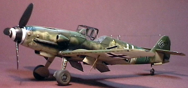
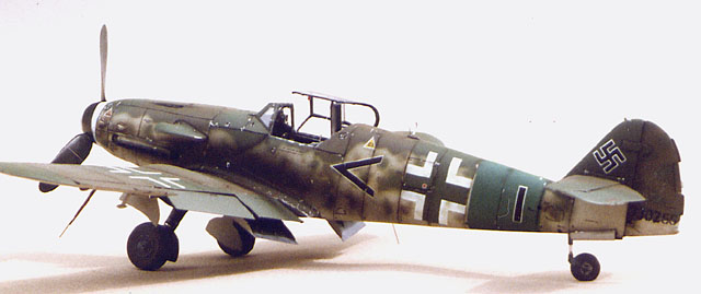
Messerschmitt Bf 109K-4 by Glenn Irvine
As a keen modeller of late war Luftwaffe aircraft, I knew I would eventually have to build a 1/48 scale model of the Messerschmitt Bf 109K-4. For the uninitiated, the K-4 was the last production variant of the Messerschmitt 109 produced by the German aircraft industry during World War II. Due to the continued development of the airframe for
increased performance, the incorporation of the DB 605D engine and other
streamlining of production changes, the K-4 has some unique physical
characteristics that are the subject of this conversion and superdetailing
project. Broken down into steps the major work required to
convert the Revell G-10 to a K-4 are:
I used a good article by Don Alberts which was passed
to me in photocopy form, so I cannot tell what magazine it was published in,
though the article did come out 2 years after the original release of the kit
by Revell. I also used a set of 1/48th scale plans by Tom Seay and the
diagrams in the Model art book on the 109 G&K. Also of enormous help was
the Model Graphix book on the 109. Various other references were also used
including John Beaman’s ‘Last of the Eagles’.
Delving into the mystique of the '109' is a problem for
any modeller attempting to build an accurate representation, as there are more
'experts' on this aircraft than any other aircraft except perhaps the
Spitfire.
Perhaps I am no different. When I build a model I
attempt to research as thoroughly as possible and familiarise myself with
all possible aspects of the physical structure before cutting plastic, as this
allows one to make more accurate judgements of existing photos and drawings.
Never be afraid to change your pet theory at the last moment or, as often
happens, after the model is completed, when new information comes to light.
With the best will in the world, a modeller/researcher cannot be 100%
accurate all the time. And last, my philosophy on modelling. Good models
fool the eye and brain into seeing something made of many scale size
components, just as the real thing is. The secret to this is to build all the
visible components of the model as close to scale thickness and size. Also to
include all the components that make up a visible assembly. This produces a
‘busy’ appearance that is convincing to the eye and taken overall gives
the impression that the model is a complete mechanism made of many parts that,
even though it is tiny, looks like it could start and fly away.
There are a number of changes required to the 1/48
scale Revell/Monogram Bf
109G-10 kit to bring the
level of detail & accuracy up to what I required, and to make a decent
representation of a Bf 109K-4.
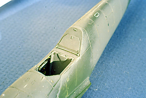
I started by sanding the whole airframe, as the engraved lines have slight ridges either side of them. This was followed by attention to the following details:
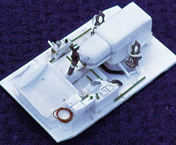
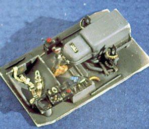
Cockpit detail completely scratch built to K4 standard.
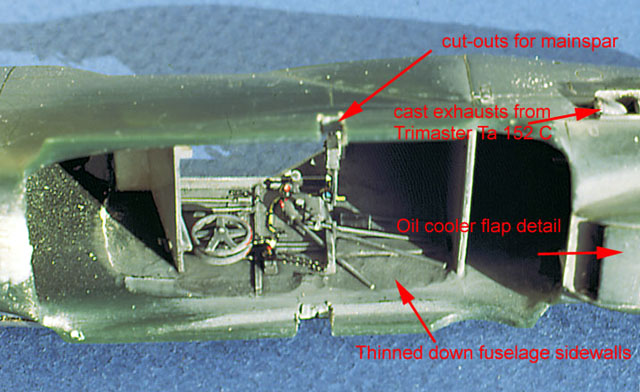
The Cockpit None of the G10 cockpit was used. Thinning down the components where detailing is to be
carried out allows for more room and accurate detailing. This was done in the
cockpit and exhaust areas. The fuselage halves assembled and detailing built
up on the sidewalls and rear bulkhead area. The cockpit floor was cut to fit from .020” sheet
styrene with thin strips of styrene front and rear for location on the
bulkheads. Detailing of the cockpit floor/tub was then carried out. This
allowed repeated trial fitting throughout construction.
Starting with the sidewalls, all detail was built in down to a datum scribed on the fuselage sidewalls where the cockpit floor would be fitted.
Formers and cockpit sills were constructed from microstrip and stretched sprue. A new circuit breaker board was built from sheet strip and sprue. Wire harnesses were made from fine multistrand wire – take 3-5 strands, dependent on loom size, twist together, apply super glue to hold together then cut and bend to suit. Sometimes annealing the wire by preheating red hot with a match or candle will help in forming the loom, but do this before gluing the wire together with cyano.
The seat base was made by heat forming .010" sheet over a wood
former, then a section the right width was cut and side plates glued on, then
trimmed and sanded. The seat back is usually removed from most 109's to create
more space for the pilot. The panel exposed by this is a press formed alloy
panel to cover the armour plate and mounting bolts. A replica of this was
created by using .005" sheet
and strip, with white glue drops to represent the bulges to cover the bolt
heads and for fairing in the sides to create a pressed look. Seat belts were
made from adhesive lead tape and Model Technologies buckles,‑ their
rudder pedals were also used with straps from tape. The floor scuff plate is different to the G10/G6
variants and had to be made from sheet and sprue. The Motor cannon breech
cover was constructed from solid styrene shaped to suit and a retaining strap
from adhesive alfoil tape, with a catch from wire and stretched sprue. The control column was made from lead wire and the grip
from the G10 stick, wire harness from fine wire and stretched sprue details. A
boot for the bottom was carved from styrene with a motor tool and a micro ball
bit. The right console is completely different from all
other variants too and was constructed from styrene, lead and copper wire. The
circuit breaker panel was scratchbuilt and a representation of the labelling
was achieved using portions of 1/72 and 1/48 stencilling decals. The clips for
the oxygen hose were made from sheet aluminium.
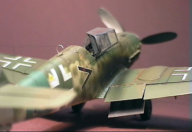
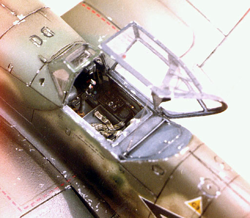
The armour for the canopy was made from sheet styrene and clear sheet. The canopy was vacformed over a master made from the kit part and detailed with internal framing made from lead wire, catches made from styrene strip, stretched sprue and adhesive foil tape. The gun sight was built from styrene sheet clear acetate, rod and stretched sprue. The rear cockpit panel behind the seat was filed flat and an access door made from .005” sheet with catch and detail added from sprue and strip.
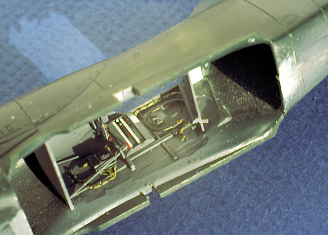
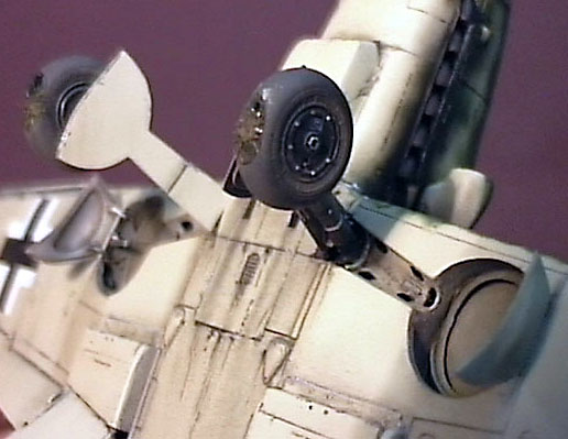
The Wheel Wells I thinned down the area of detailing on the inside of
the upper wing surface, I squared up the moulded wheel well liners and then used
them to mark a matching reference outline on the upper wing inner surface. The
liners around the tyre area were removed and replaced with wing spars and the
associated mechanical detail of the outer door retracts and the electrical and
hydraulic lines of the inner wing area. The upper wing surface was detailed with
a representation of the upper wing skinning including cut out for the larger
tyre using 5 thou sheet. The recesses for the oleo legs were thinned from the
inside and the various punch throughs were opened up. The tail wheel well was thinned down and detailed with strip and a new tall tail wheel oleo was turned up on the unimat and a fork made from brass sheet. A new wheel was turned up from a spare found in the scrap parts bin. The doors were vacformed over a master and the copies detailed with inner structure, hinges and retract mechanism. (There has
been much dispute over the method of actuation, wether the doors closed after
the tail wheel was extended or not. After examining factory drawings and other
references, it relied on the oleo leg to open and close the doors by working
against a linked bellcrank arrangement, the mechanism was purely mechanical and
would have been open on the ground, provided the tail wheel extension and
retract mechanism still functioned, as these were prone to leaking hydraulic
fluid they tended to come down in flight, so as a practical field fix the
mechanics would have locked the tail wheel down and manually shut the doors,
hence the photos of the doors closed on the ground.) The main oleos were cleaned up and detailed with brake
lines and brake line retaining straps made from baremetal foil. The main wheels
were poor representations of the wide wheels fitted to the late ‘G’s and
‘K’s , so I cast up copies of the wheels in the Fujimi K4 kit and used
these.
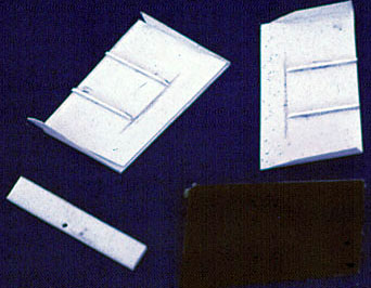
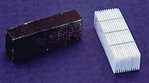
The outer doors were vacformed over masters built up
from sheet and putty and the copies detailed with framing and hinges and
actuators. The main doors were scratchbuilt from layered sheet and strip to form
more accurate and in scale components, including the guide rods and other detail Control Surfaces All the control surfaces were separated and their leading edges built up and the wing trailing edges were chamfered and the parts repositioned to a more ‘candid’ position. The ailerons were modified to have adjustable trim tabs as depicted in various plans. At the time of building there was some contention as to wether K’s actually had them in production. As there were no clear photos available to me at the time indicating wether this was in fact the case, I decided to fit them, based on photos of them fitted to G-6’s. These
photos are of aircraft flown by Experten, Barkhorn
(pg. 61 middle, Koku Fan No. 57) and Grislawski, (pg.113 Messerschmitt Bf
109 F,G & K Series Prien & Rodeike). Based on this, I think that new
modifications to production were trailed at the front by Experten and based on
their reports, were then introduced into production. . The rudder was separated and the fin and rudder was
built up with card and cyano to match the plans. The
rudder was thinned down, the bottom built up and the flettner tab was moved and
the operating mechanism was scratchbuilt. The external trim tabs on the rudder
were lost during the thinning process, so new ones were made from 5 thou sheet.
The leading edge slats were separated and assembled, new leading edge detail for
the wing was built and tracks attached to the slat from strip.
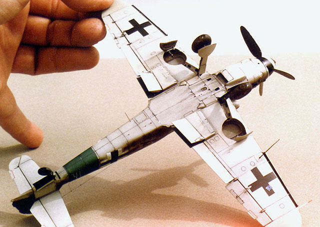
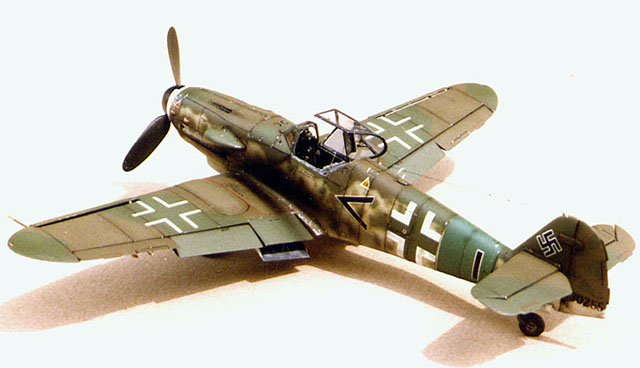
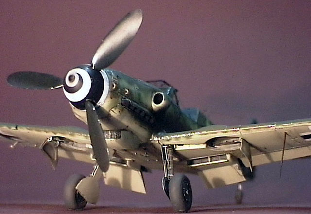
Other Details The prop blades are too narrow and too short, so they were built up with superglue over .005” sheet and sanded to shape. The spinner was chucked in my Dremel and sanded to a more accurate shape and the cannon blast tube installed from brass tube. This brass tube was extended thru the spinner backing plate and a short section of larger slip fit tube was installed in the fuselage to allow the spinner to be fitted later. The spinner was fitted up to the fuselage and the forward cowl sanded and filled to match the spinner. The cowl on the Revell kit is quite good but is unfortunately not asymmetric and needs building up where the supercharger intake fits. The intake needs modifying to increase the size of the mounting flange as it is a little undersized. A little reshaping is also necessary to accurately portray the scoop.
As moulded the wings in the Revell kit won’t give you enough dihedral, so the wing roots on the upper halves are sanded until the correct dihedral was reached and a mainspar from .040” sheet was glued in to ensure the angle remained fixed as the plastic in the Monogram pressings was a bit ‘soft’ and flexible. The moulded on ETC rack was removed and the vent and ejection ports for the engine cannon and upper cowling MG. were scratchbuilt.
The restraining cable was made from wire and a spring was wound and fixed with white glue. The aerials were made from wire, brass shim for the DF loop and plastic as appropriate. The wing tip navigation lights were built from Perspex with a lamp drilled and coloured from behind. It was then sanded and polished when glued in place. It was made slightly larger than the lamp so that new panel lines could be scribed over it and paint would replicate the metal retaining clamp.
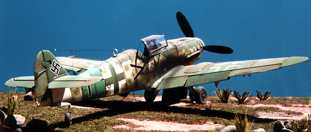
After much gnashing of teeth, I finally decided on an aircraft of JG.27, and the mixture of late war colours used in Don Greer's interpretation sort of got me started. Next I had to find references and decals, as I wasn’t happy with Aeromaster’s version, after close inspection of the photos, I felt that the chevron was longer than was available and ended up using a variety of sources including MSAP Microscale and Aeromaster as well a few others.
The Reich defence band was sprayed on and masked off, then the camo was sprayed on using spaced card masks and the mottle was done freehand. The rudder with its distinctive pattern was sprayed using a mask. The blugrau undersurface colour was mixed from 02 and white and the 81 and 82 were Xtracolour straight from the tin. Weathering was done with an oil wash and paint chipping, suitable oil leaks were added using Gunze ‘oil’
Ton Seay’s plans in 1/48 109 part 2 Squadron signal 109 F,G,& K series by Prien and Rodieke Monogram Close up 16 109 K Model Art book on the 109 G-K Various books on Luftwaffe camo, Monogram, Kookaburra etc. John Beamans Last of the Eagles Model Graphix on the 109
Click the thumbnails below to view
the images full-sized.
Model, Text and Images Copyright © 2000 by
Glenn Irvine
|

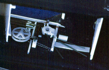 Some photo etched parts- chain drives , buckles and
rudder pedals were used. Trim wheels from the new Hasegawa 109 E were used. A
new
Some photo etched parts- chain drives , buckles and
rudder pedals were used. Trim wheels from the new Hasegawa 109 E were used. A
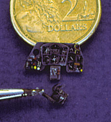
new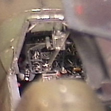 I assembled to the front panel aligning the holes with
the instruments. I scratchbuilt new instrument bezels from sheet styrene and
the knurled ring around the artificial horizon was made on a jewellers lathe I
had access to. I assembled the bezels to the facia, painted and dry brushed
before assy. Once dry assemble to the front panel aligning holes with the
instruments.
I assembled to the front panel aligning the holes with
the instruments. I scratchbuilt new instrument bezels from sheet styrene and
the knurled ring around the artificial horizon was made on a jewellers lathe I
had access to. I assembled the bezels to the facia, painted and dry brushed
before assy. Once dry assemble to the front panel aligning holes with the
instruments.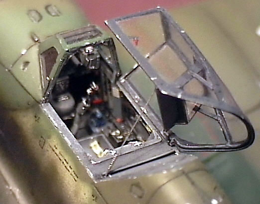
 The canopy was
vacformed over an accurate master that incorporated the gentle fore/aft bulge in
the upper plexiglas that is not visible in any kit canopy so far or the
Squadron/Falcon vacform.It was then outfitted with interior framing and
scratchbuilt head armour and details. It was painted, washed and dry
brushed to pick out the detail, a few touches of colour for the emergency
release handle were also added.
The canopy was
vacformed over an accurate master that incorporated the gentle fore/aft bulge in
the upper plexiglas that is not visible in any kit canopy so far or the
Squadron/Falcon vacform.It was then outfitted with interior framing and
scratchbuilt head armour and details. It was painted, washed and dry
brushed to pick out the detail, a few touches of colour for the emergency
release handle were also added.