|
Curtiss BFC-2 Goshawk
by
Arlo Schroeder
|
|
|
Scratchbuilt 1/16th
Scale Curtiss BFC-2 Goshawk |
Text
by Ben Backes

HyperScale is proudly sponsored by Squadron
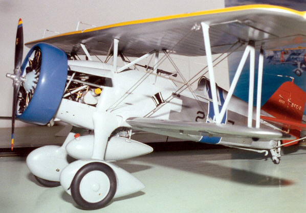
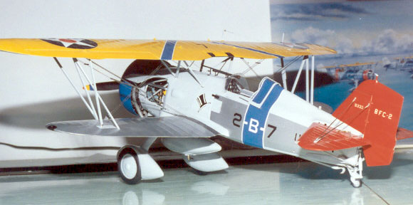
This model represents the 3rd section
lead of VB-2B “High Hat Squadron” aboard the USS Saratoga circa 1936.
Building time for this project was 1,391 hours.
Features include working shock absorbers on the
landing gear, working control surfaces and hinged engine access panels.
Automotive acrylic lacquers were used to paint this
model, and markings were custom-made dry transfers from Woody Vondracek.
Construction
Photo Feature
|

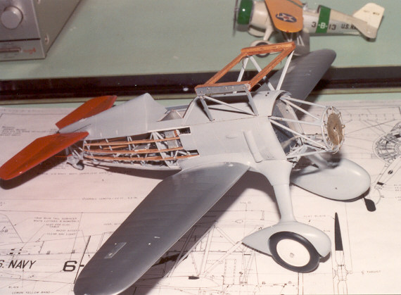
- The internal structure and landing gear is
soldered brass tubing.
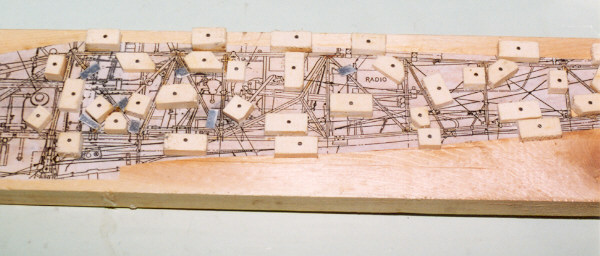
- This was accomplished with the aid of a
soldering jig. First a drawing of the internal structure was glued to
a piece of wood, then small wooden blocks were nailed at strategic
locations with the proper angles cut into the corners to hold each
piece of tubing in its proper location while the soldering was done.
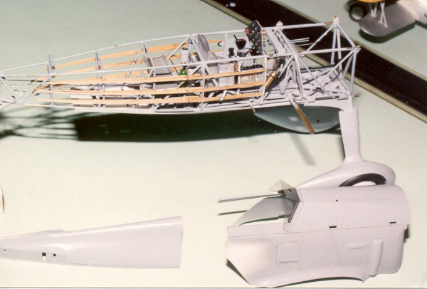
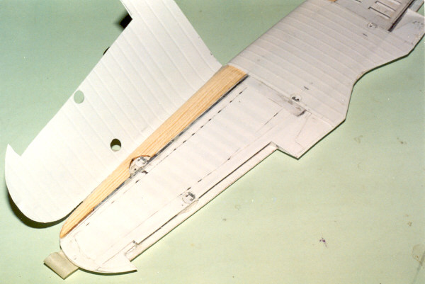
- Arlo used real wood stringers to simulate the
real wood stringers!
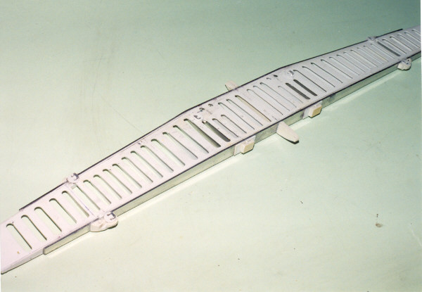
- Underside of the upper wings internal
structure. Sheet aluminum sandwiched to the plastic spars adds
incredible strength. The attachments for the struts are metal too.
- Upper view of the upper wing internal
structure. Plastic was used for most of the spars, but were the
struts attach aluminum was used for added strength.
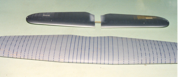
- The finished lower wing sits behind the wood
pattern for the upper wing skin. Thin pieces of tape were laid along
the location for each rib. When the skin is vacuum-formed these will
create raised bulges. It looks as if small sections of blue tape are
in some places, but this is not actually the case. Different colors
of scrap tape were used and some of the pieces were alternating blue
and white patterns.
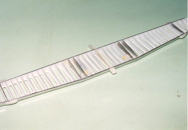
- This is the underside of the upper wing, before
the skin is applied. Wood has been carved and glued to the aluminum
to provide something solid behind the skin of the leading edge.
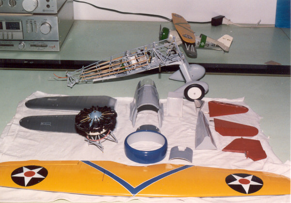
- Many of the major components painted and ready
for final assembly.
- The wood box is a temporary jig to get the upper
struts lined up correctly.
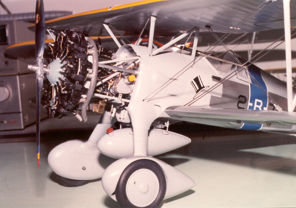
- The Wright R-1820 engine is attached and behind
it is the accessory section. The flying wires are flattened aircraft
model safety wire.
Model and Images Copyright ©
2001 by Arlo Schroeder
Text Copyright ©
2001 by Ben Backes
Page Created 10 October, 2001
Last Updated 04 June, 2007
Back to HyperScale
Main Page
Back to Features Index
|
 Home
| What's New |
Features |
Gallery |
Reviews |
Reference |
Forum |
Search
Home
| What's New |
Features |
Gallery |
Reviews |
Reference |
Forum |
Search