|
North
American
F-86E-30 Sabre
by
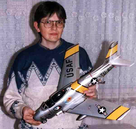
Robert Blaschke
|
|
|
F-86E-10 Sabre in 1/18
Scale |

HyperScale is proudly sponsored by Squadron
Some time ago I decided to leave my job but I had not decided on my
next career move. I saw an advertisement in a model magazine that
offered a professional modeling job. I decided to try it. It gave me one
year and one month of building special models and accessories.
The first models I built were without exterior painting. My role was
to build quality interiors, wheel wells and other inner surfaces and
details.
Finally, the time came for me to build a complete model. In fact, it
was also my swan song in my short career as a professional modeler.
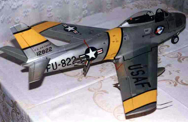
The model was a North American F-86E-10 Sabre.
The model is HPH, in 1/18 scale. The technology is completely
different from a classic plastic kit. The basic parts are laminated into
negative forms and then laminated together. The kit includes the
complete fuselage with solid wings and vertical stabilizer. Additional
pieces, also from laminate, are ailerons, flaps, horizontal stabilizers,
rudder, two parts of intake tunnel and canopy frame.
All other parts are PU resin pieces. Many additional details had to
be scratchbuilt.
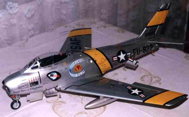
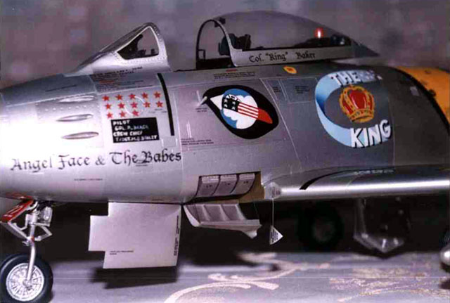
First I had to decide, what aircraft it will be at the end, because
there were no available in this scale. I had many schemes from which to
select. In the end I came to a decision - I chose "The King".
There were some problems. The model was F-86F-30, as it was designed
primarily for Japanese market. I hesitated, how much to rebuild. I
shortened the wingspan and opened up some fuselage "holes"
that the F-30 did not have. I left the slots as they were, although at
E-10 the wing root should not reach above the ammunition door. I took a
decision to open it up and make the cartridges visible and so I had to
make the root piece of leading edge, which this airplane had not. Never
mind. It looks good anyway.
But one thing was bad - the wings were swept too far - three degrees
more then reality! At least the panel lines were in fact at good angle
to leading edge, i.e. they were three degrees swept back. I decided to
let it be as the correction would be too difficult.

The main remaining problem was how to paint the yellow bands, if I
don't want to make the wrong wing angle immediately apparent. My answer
was to paint them accurately, and not align them with the panel lines of
end part of the wings.
Fuselage
Exterior
The work started with fuselage.
First I drilled out all the openings and removed the material in the
wheel wells, speed brake bays and canopy. The panel lines of front wheel
well were wrong - too far aft. If I let it be, I could never place the
ammunition door correctly. I shortened it to the right dimension. For
all this dirty work I used my highspeed Proxxon machine, with cutting
discs and sanding bands.
I then washed the whole model in detergent and in toluene to remove
all remnants of laminating separator. The next tool in my hands was a
big rasp file. I removed all the excess resin material in the lines
where the basic parts were laminated together. No.600-1000 sandpaper was
used to prepare the parts with a smooth finish.
Of course there were a lot of little holes - air bubbles in the
resin. I used a polyester two-compound fine putty PrestoFlex for big
areas and Tamyia putty for fine jobs. All the missing and destroyed
panel lines were then newly scribed. After a year in this business I had
a lot of practice with this. I drilled out the missing rivets with a
0,5mm drill. Anyone who works with resin parts can attest how every
sanding brings myriads of new bubbles to the surface. Experience and
instinct for this kind of work can help here.
Fuselage
Interior
This included fitting the intake tunnel, interior, wheelwells and
speed brake bays. With the exception of the intake tunnel (that had to
be glued from two laminate parts) all other parts were PU resin. Fitting
was not good, so massive puttying and sanding was required.
Cockpit
The cockpit interior was a big and heavy part, but not heavy enough.
I therefore added a lot of lead weight to the nose to avoid the model
being a tail-sitter.
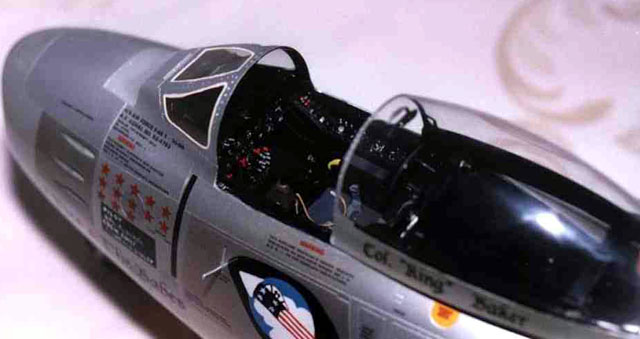
The cockpit had to be painted before gluing in. I wanted to paint it
light gray, as it is very nice to me - black instruments with white
symbols and hands on light gray panel, but that would have been
inaccurate - the interior of this bird was black, as it could be seen
from various pictures. So I painted it black and then all the
above-mentioned hands and symbols white with 5/0 brush. Some pieces had
to be red, some yellow. Complicated piping behind the ejection seat I
made from solder and paint it black too.
Wheel
Wells and Speed Brake Bays
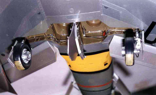
I drew a technical scale drawing of the wheel wells and speed brake
bays as I needed to have clear idea of every part of piping and wiring
in them.
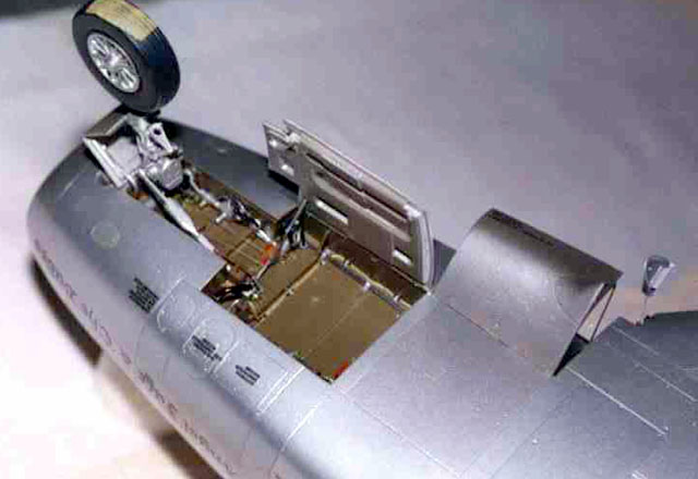
The front wheel well was too long, so it had to be shortened. After
gluing it all together I painted it interior green and fitted with
parts, piping and wiring, as I can read it from the pictures I had. (The
color was really interior green, although on my pics it seems to be
brown. It could have been a problem with my camera, I don't know.)
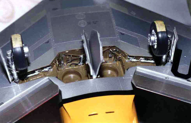
Many of the parts in wheelwells and also in speed brake bays were
scratchbuilt.

The piping is from 0,6 or 0,8 mm solder.
Undercarriage
Undercarriage legs were PU resin parts with steel rod cast in. The
front wheel needed to be detailed with many parts, especially for the
front wheel steering. Wheel discs were well detailed, but some putty had
to be used and some sanding and engraving should be done on the tires.
Both the wheelwells and the undercarriage legs had to be glued with
massive amounts of epoxy, as they had to bear the full weight of this
heavy model.
Windscreen
and Canopy
The windscreen and canopy were stretched on the master not from
acetate but from acrylic sheet, 0,8mm plexi. It is not easy to cut out
the right shape, especially if you need to fit it on laminate frame. And
it is very fragile, too. But with a lot of patience and experience it
was completed. The canopy had to get open and close with perfect fitting
to windscreen. This was an important demansd of the company I work for.
It proved another tough part of the project, but it was possible.
Rivets, drilled in the frame of canopy are important. They reinforce
the impact of the model in this scale.
Unlike a regular plastic kit, this one was painted with PPG-Deltron
BC-type acrylics.
When all the surfaces were nicely prepared for painting, I sprayed it
with a reactive basic color and one shade of silver. Then came masking
and re-masking and another and another shade of silver. I think I used
about 10 shades. One with drop of white another with drop of blue, red,
yellow etc. The effect was quite nice.
Then more masking for yellow bands with black borders, another for
4th FIW emblem and another paintbrushing. All the insignias were
paintbrushed with plotter cutted masks. The emblem "THE KING"
was masked and paintbrushed too, color by color, the crown was at the
end shaded and make up with brush.
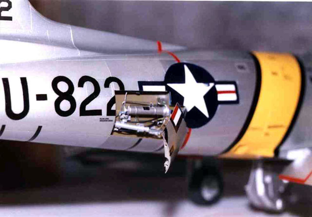
I use some decals. I received stencils with the model, but I made the
inscriptions "Col "King" Baker" and "Angel Face
& The Babes" myself on laser printer so as numbers 12822 on the
tail.
All the model I sprayed at the end with clear coat from spray can.
No weathering was added. I am no good at this kind of work and it was
not necessary in this case.
Finally, I glued the pitot tube glued together, bent an emergency
fuel dump from large hypodermic needles, and scratchbuilt ammunition
cartridges and their doors.
In conclusion, I was pleased with the result. My professional
modelers career ended, but I am not complaining. It was sure interesting
part of my life.
Click the thumbnails below to view
the images full-sized.
Use the "Back" arrow of your browser to return to this page.

Model, Text and Images Copyright ©
2001 by Robert Blaschke
Page Created 28 April, 2001
Last Updated 04 June, 2007
Back to HyperScale
Main Page
Back to Features Index
|
 Home
| What's New |
Features |
Gallery |
Reviews |
Reference |
Forum |
Search
Home
| What's New |
Features |
Gallery |
Reviews |
Reference |
Forum |
Search