|
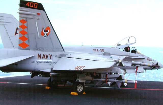
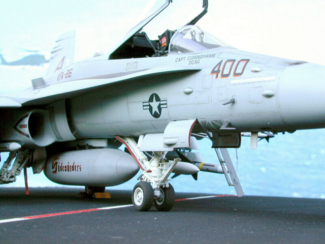
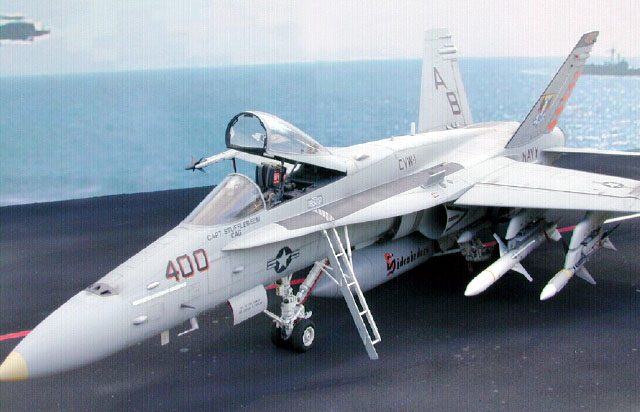
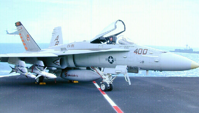
F/A-18C Hornet
VFA-86 Sidewinders
USS George Washington
|
 |
|
F/A-18C Hornet |
by
Fred List

Hasegawa's
1/48 scale F/A-18C Hornet is available online at
Squadron
For those who have
not built one of Hasegawa’s Hi-grade modern jet aircraft kits (F-14, F-15,
F-18 etc), the prospect can be intimidating.
Upon opening the box
you’ll be greeted with no less than 6 sprues of gray or clear
plastic as well as white metal landing gear, a small photo-etched brass
sheet and a relatively comprehensive instruction booklet. In short,
there’s a lot of stuff here. Those modelers more used to dealing with
World War II single engine fighter kits might be tempted to quietly put
these kits back in the “to be done later” pile and tip-toe away, but I’m
here to tell you… fear not, it isn’t as tough as it looks. What it will
require is time.
My overall strategy
for this kit like many others was to build the major structural components
first to get all the filling and sanding out of the way, then add the
small items like antenna, wing pods and landing gear. This necessarily
means that I deviate from the sequence shown in the kit directions.
For this kit, I
elected to start construction with the landing gear and landing gear bays
instead of the cockpit. This was for no other reason than simply a change
of routine.
The metal gear is
very nicely cast but will require a bit of work with an X-Acto knife and
sandpaper to remove the mold line. Running the knife gently along the mold
line with the edge away from you will remove the lion’s share of it.
Follow that with a few passes with a Fine (600 grit) sanding stick to
smooth and reshape the curve. After adding the plastic parts to the
landing gear with CA glue, I primed them with a light coat of Humbrol gray
Primer. The paint highlighted some areas where additional sanding was
needed, after which I re-primed. When dry, I painted the gear with Model
Master Insignia White, which is a gloss and set them aside. The gear bays
were painted MM Flat White and the hydraulic details painted in. A few of
the more conspicuous hydraulic lines were added using 20-gauge aluminum
wire. A dark ochre wash was applied to provide some depth and weathering.
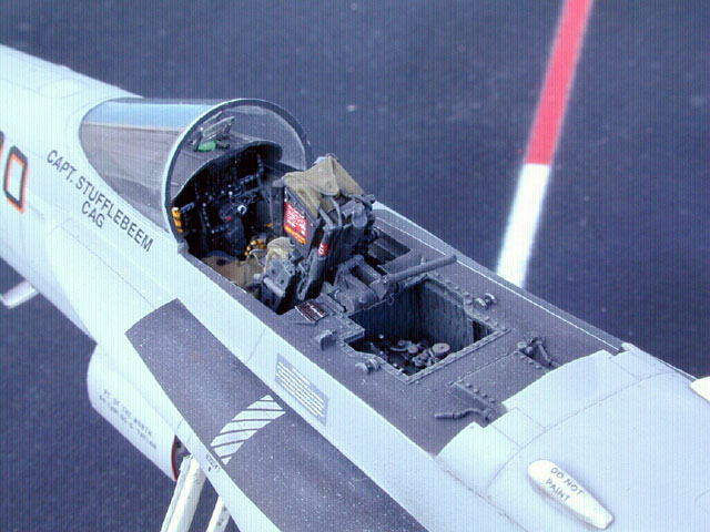
I decided I couldn’t
put it off any longer. I elected to throw caution (and dollars), to the
wind and obtained the Black Box F-18B cockpit set and the F-18
Multi-Purpose set. While the kit cockpit is fairly well done, there is no
sidewall detail and the mail instrument panel is somewhat two-dimensional
even with the photoetch add-ons. Both the BB sets were as expected,
beautifully cast with no flaws. I should mention in case you’re curious,
buying the F-18B set and the multi-purpose set allows you to build
any variant from A to D with both Martin Baker SJU-5/6 & SJU-17 NACES
ejection seats.
The cockpit tub,
sidepanels and main instrument panels were airbrushed Dark Gull Gray FS
36231 while the Ejection seat, rear panel, avionics bay and canopy
actuation equipment were airbrushed Interior black. (Interior black is
actually a very dark gray that I made up from 50% Floquil Weathered Black
and 50% Flat Black.) The instrumentation and seat details were
hand-painted in using several different sources of reference. The MFD
displays on the instrument panel were painted Gloss Black, then a coat of
Humbrol Clear Green was put on to try to give the green glow that these
panels tend to display. The effect was not very visible. The instrument
dials were drawn in using a very sharp silver pencil. One puzzling issue
was the ejection-seat cushion color. Of the four different comprehensive
photo sets I had of the SJU-5 ejection seat, no two had the same color of
cushions! The khaki color I elected to try to duplicate was from photos of
an early SJU-5 seat.
Assembly and
installation of the BB cockpit was simple and was accomplished just prior
to gluing the fuselage halves together. The only caveat was that the main
instrument panel seemed to sit slightly too far forward and was largely
hidden by the coaming. This conflicts with actual cockpit photos that show
only a small overhang of the coaming over the instrument panel. Some
effort was made to shorten the overhang by sanding off a bit, but this did
not fully correct the problem. In the end it didn’t look bad to me, and I
didn’t feel the problem was worth the effort that would have been required
to correct it. Care should be taken when installing the avionics bay and
deck behind the ejection seat. The Black Box resin part replaces kit part
G3 for this step, but the resin part is not
nearly as robust as the plastic part. Any pressure up, down, or from the
sides could easily crack this fragile piece. To make things worse the fit
of this piece was a bit loose which required me to fill along the sides
with Squadron White putty, sand smooth and put on a coat of Mr. Surfacer
500. Predictably, later on in the construction of the fuselage I cracked
one of these seams, which fortunately only required another application of
Mr. Surfacer and some light sanding to fix. If I had it to do over again I
would support the resin piece with a couple of 2mm strips of Evergreen
plastic to support the resin and help prevent flexing.
At this stage I
decided that I should make sure that all the necessary holes were opened
up for the wing pylons and external details, after which I glued the wing
halves to the upper fuselage section.
Here I deviate from
the directions by jumping to Step 5 and doing everything but the nose
cone before I do Step 4. I took the lower fuselage half and carefully
fitted the side panels, which include the engine intakes and glued them
with Tenex 7R applied to the inside seam. This is a critical step. The
fuselage sides are convoluted and you need to be careful that the side
panels fit flush with the rest of the fuselage as much as possible. After
these pieces were on, I fixed any seams that I could find with either Mr.
Surfacer 500, or Liquid Paper.* This is the time to get these seams tight,
because once the upper and lower fuselage goes together it’ll be a bear to
get to with a sanding stick. Since I was doing an FA-18C, at this point I
removed the AN/ALR-67 antenna bulges from the underside of the intake
nacelles, as the C model didn’t have them. In addition to the fuselage
sides the intakes should also be added at this point, because there is a
definite step between the fuselage and the intake piece which needs
attention.
If you haven’t used
Liquid Paper as a filler, let me say that I use it when a gap is too wide
for Mr. Surfacer 500 to fill, but too small to accurately apply putty
without careful masking. The Liquid Paper goes on as a thick liquid that
dries very quickly. I can usually sand in 10 – 20 minutes. I find it’s not
as difficult to sand as gap-filling CA, which means I lose less
surrounding detail. Liquid Paper does not hold a scribed line as well as
Mr. Surfacer, but I’ve done short scribed lines across a seam filled with
LP and had no problems. LP sands as smooth as glass and contrary to what
I’ve heard some others say, I’ve never had it lift off with masking tape.
Very Important: Don’t use the new water based Liquid Paper. It doesn’t
work. You’ll need the old type, the kind that’ll make your eyes water, to
do the job.
Once the cockpit was
installed, the fuselage halves were glued together. This step requires a
lot of adjusting before the two halves snap into place. The underside of
the Leading Edge Extensions (LEX), in particular had trouble mating up on
my model. Small padded clamps were needed to hold the upper and lower
halves together. Once everything was in the correct position I used Tenex
7R to bond the halves together. The vent holes and the muzzle opening for
the 20mm gun were opened up with a scalpel and micro-drills then the
insert was glued onto the nose cone. The insert needed considerable
filling and sanding to fit flush. All the rest of the filling and sanding
of the nose cone seams are best done before the nose is glued to the main
fuselage. Once the nose is on, I jumped to Step 14 in the kit directions
and installed the spine piece behind the cockpit as well as the
aforementioned avionics bay and deck. The remainder of the kit directions
were generally followed except I did not install the landing gear until
after the painting.
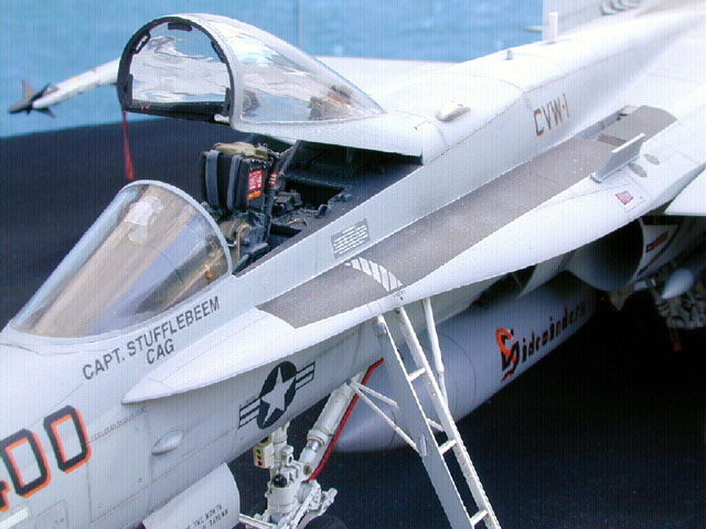
One concern I had in
the construction was the pronounced mold line down the center of the
FA-18s canopy. I hadn’t done this much cleanup on a clear piece before,
but it turned out to be an easy fix. I wet sanded with a medium grit
sanding stick until the canopy was smooth, then wet sanded with
progressively finer grits until the canopy appears fairly clear. This was
followed with a thorough polishing with plastic polish. The canopy and
windscreen were then washed in soapy water, dried, dipped in Future,
covered and allowed to dry for two days. After masking the glass areas
with Bare Metal Foil the windscreen was glued to the fuselage and the main
canopy was temporarily affixed in place over the cockpit.
One difficulty I
did run into with the construction of this model was the alignment of
the left and right main landing gear. If the gear don’t angle down and out
at exactly the same angle, it produces a very noticeable tilt in the
plane’s stance. Make sure the wheels are installed on all the gear prior
to gluing them into the wheelbays. I stupidly installed the gear first,
then put the wheels on, only to find out I had wheels pointing in every
damn direction, but straight! It seems that the left and right main gear
were both subtly bent and there was no way I could get enough leverage to
unbend them while they were attached to the plane. After gingerly applying
some acetone-based nailpolish remover to the glue I was finally able to
remove the gear without destroying either the plastic or the paint. The
wheels were installed and the landing gear was repeatedly test fit to be
sure the angles matched. When I was sure I’d got it right, the glue went
back on, and I felt like I had dodged a bullet. Minor adjustments
to the main wheels camber and toe-in can be made by bending the axle, but
you’ve got to be VERY careful. The front gear installation was not a
problem.
Painting for this
ship was a snap. The main colors are Dark Ghost Gray (FS36320) and Light
Ghost Gray (FS36375). I used Testors Model Master enamels lightened with
white (1 part white to 4 parts gray), for scale effect. To check the that
the colors were right, I sprayed both lightened colors onto a scrap sheet
of Evergreen plastic that had been primed in light gray. Once I got the
ratios where I like them, I made up, what I thought was more than enough
of each mixture. In the end all of one color was gone and only half an
ounce was left of the other. The painting itself was thankfully
uneventful. After the paint was allowed a day to dry I airbrushed two thin
coats of Future about 8 hours apart and allowed that to dry for another
day.
The decals for this
aircraft were done by CAM decals. Sheet No. 48-073. I chose this scheme
for no other reason than I liked the look. The CAM decals were very thin
and went down well with a drop or two of Micro-Sol. Due to the frequent
repainting and the fact that this was one of the oldest FA-18C’s,
stenciling was minimal. Two thin coats of Future were applied and allowed
to dry fully over two days before I started the weathering.
The aircraft modeled
was the Wing commander’s machine, but it was also the eighth aircraft in
the first block (23) of FA-18C ‘s built in 1987, (and thus was nearly 10
years old at the time depicted in the model.), so I wanted to keep the
weathering moderate, but clearly visible.
The first step was
to simulate fading paint on the upper surfaces of the aircraft. This was
easy, since the clear-coat deepened the base color and I just needed to
spray a highly thinned base color over the most exposed areas. Coverage
was very thin since I didn’t want to highlight too much and I was careful
to stay away from the decals. The area along the spine and wings got the
majority of the attention. The highlight color was sprayed from a fine
tipped Badger 200 airbrush at 9 psig, keeping to the areas that would be
faded by the sun the most. The color was applied to the center of each
panel and worked out toward the seams keeping the sweep of the airbrush
parallel to wind flow. When finished the results are very subtle. If a
mistake is made or if you don’t like the look you can overshoot the area
with Future, Doing this will make highlight color will blend in with the
base color and you can start over. A couple of panels were also masked off
using Post-it notes and sprayed more thoroughly to simulate re-painted
panels. A very dilute black-gray was sprayed aft of vent openings and the
wing folds to simulate wind blown exhaust oil, dirt and graphite
lubricants and highly thinned flat black was lightly sprayed around the
engine nozzle to dirty it up a bit.
The shading, of
aircraft panel lines is one of the ongoing debates that never ends among
modelers. Some like very dark, pronounced lines and others, no lines at
all. While it depends greatly on the subject, generally, I stay close to
the middle, with subtle shading of panel lines over most of the aircraft
becoming darker along frequently opened doors and plates that would be
exposed to more grime. But there is no right or wrong here. The payoff is
not in how it is done, but how well the modeler does it.
Simulating shadows
underneath antennas and wing pylons etc., and to very subtly define the
panel lines was done in my usual way, with tinted Future. I make up this
wash by putting a drop or two of brown or ochre and two or three drops of
black acrylic paint into a small container of Future acrylic. This makes a
colored mixture, not unlike Tamiya clear Smoke acrylic paint. I make up
the mixture a batch at a time and it lasts for months. Using this
concoction I carefully draw a fine 000 brush along all the panel lines.
The effect once dry, is similar to a typical enamel wash and can be
repeated several times to get the desired effect. Once the panel lines
were done, I shot the whole model with 2 coats of Polly-Scale Flat.
Final weathering is
done using artists pastels to simulate exhaust stains, graphite stains and
foot traffic along the wings and LEX. The final very thin coat of
Polly-scale flat tones down the pastels, which may need to be touched up.
I found Dave
Aungst’s Weathering Feature here on HyperScale to be a great aid in
helping me develop additional skill in this area. I don’t follow his steps
to the letter, but his article is full of good ideas that helped me define
a consistent technique for weathering scale models.
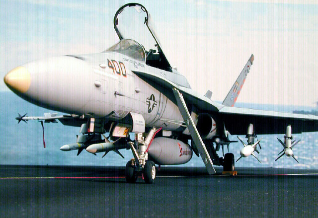
I wanted the
ordinance load to reflect a typical loadout for Operation Southern Watch,
enforcing the no-fly zones over northern and southern Iraq. The F/A-18C
Walk-Around book had a couple of reference photos of Hornets flying
patrols, and the US Department of Defense website has an enormous amount
of archived photos that showed a wide array of loadouts for this
operation.
The four AIM-7F
Sparrow, two AIM-9L Sidewinder Air-to-Air missiles and the two AGM-88 HARM
missiles were all taken from the Hasegawa Aircraft Weapons C set. The
weapons set included the Aero-5A-1 launcher for the AGM-88s, but did not
include any provision for mounting the two Sparrow missiles under the
wings. Fortunately, a photo of the Sparrow launch adapter was soon in my
e-mailbox shortly after sending up a distress call on Plane Talking.
Thanks. From this photo I was able to make a pair of these launchers from
strips of Evergreen plastic.
The “Remove Before
Flight” flags were made on my printer here at home and hung from fine
brass wire painted with Humbrol’s Polished Steel.
Finally, the
antennas, AOA indicators, and boarding ladder were installed on the plane
and weathered. I estimate that total build time was close to 100 hours,
but keep in mind that I build very slowly anyway and the average modeler
would probably take less time to finish it.
In the end, while
not exactly a shake and bake kit, the F-18 is certainly not the beast I
imagined it to be and the time invested produced a fine addition to the
display case.
Click the thumbnail to view
the larger image on this page:
[../photogallery/photo22968/real.htm]
Text, Images and Model Copyright © 2001 by
Fred List
Page Created 03 October, 2001
Last Updated
04 June, 2007
Back to HyperScale Main Page
Back to Features Index |
 Home
| What's New |
Features |
Gallery |
Reviews |
Reference |
Forum |
Search
Home
| What's New |
Features |
Gallery |
Reviews |
Reference |
Forum |
Search